Abstract
Thin, flexible needles can be steered along nonlinear paths to reach deep anatomical structures within the human body. This study builds upon previous work involving steering of bevel-tipped needles by inserting while rotating in a duty-cycled fashion. Here we investigate how needle material and radius, duty cycle, and tissue stiffness affect needle curvature. Needles were inserted into media while rotated at a specified duty cycle and the curvature was measured. A linear relationship between duty cycle and curvature was observed across all needle materials and radii, and tissue stiffnesses. Following these observations, we developed a model that encapsulates needle and tissue parameters in order to predict the duty cycle needed to achieve a desired curvature.
I. Introduction
Needle insertion into soft tissue is one of the most commonly performed medical techniques [1]. To reach anatomical structures deep within the human body, clinicians must approach the structure in a linear path from the surface of the body. The linear approach can be limiting, for example, when injecting chemotherapeutic agents into multiple locations within an intracranial tumor. The needle must be completely retracted and inserted into distinct locations on the brain surface to reach different destinations. Multiple needle insertions can lead to greater chances of damage in critical brain structures and increased chances of hemorrhage due to inability to steer around vasculature [2]. Recently, the steering of flexible needles has become a promising technique for reaching deep anatomical structures through nonlinear trajectories [3]. When inserted into tissue, bevel-tipped needles that are sufficiently thin exhibit the natural tendency to curve toward the tip of the bevel. This is due to the asymmetric force distribution applied by the tissue onto the surface area of the beveled tip. This effect can be exploited to steer the needle by varying the orientation of the shaft during insertion [4]. This technology can potentially allow for improved biopsy or injection of chemotherapeutic agents at multiple locations within a tumor.
Our group has previously developed a control method [5] in which a needle can be steered along a range of curvatures by rotating the needle in a duty-cycled fashion (stop-start-stop) as it is inserted. By varying the amount of time that the needle is rotating, the needle can traverse a predetermined curvature (between no curvature and the maximum amount of curvature for that needle-tissue combination). It has previously been observed that the relationship between the duty-cycled spinning and needle curvature is linear [6]. This research expands on this previous work, investigating the relationship between curvature, needle material, needle radius, tissue stiffness and duty cycle.
II. Methods
A. Experiment
Ten separate needles (solid wire) were inserted into four artificial tissue simulants. Needles were inserted with the apparatus described previously [5], utilizing an independent motor for insertion and a motor for rotation (Fig. 1). The ten needles in this study included four nitinol (radii 0.13, 0.18, 0.23 and 0.35 mm; Young’s modulus, En = 50 GPa), three piano wire (0.22, 0.28, 0.30mm; Young’s modulus, En = 200 GPa), and three stainless steel (0.25, 0.30, 0.33mm; Young’s modulus, En = 193 GPa) wires. Each needle was rotary-filed to produce a 10° bevel tip; the angle was verified through light microscopy.
Figure 1.
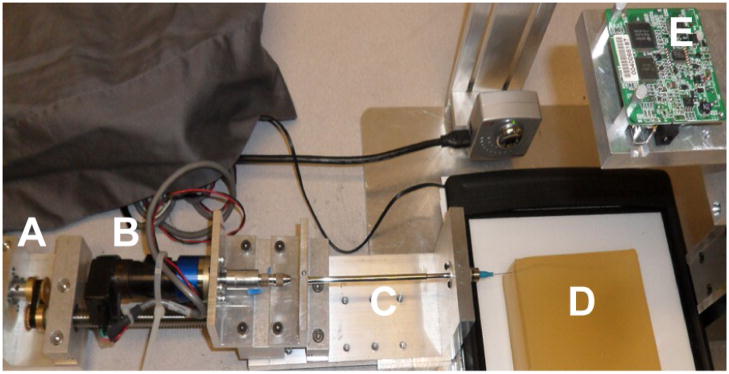
Duty-cycled needle steering apparatus. Independent motors for translation (A) and rotation (B) insert the needle (C: external sheath) into the gelatin sample (D). A digital camera (E) mounted directly above the gelatin captures images during insertion.
Two different materials were employed to create four artificial tissue simulants of varying stiffnesses. Gel A consisted of Knox Gelatine (Kraft Foods Global, Inc., Tarrytown, NY) mixed at a ratio of 1 cc of gelatin to 10 cc of boiling water (Young’s modulus, Et = 37 kPa). Gel B consisted of Knox Gelatine in a ratio of 1 cc of gelatin to 7.5 cc of boiling water (Young’s modulus, Et = 55 kPa). Gel C consisted of SIM-TEST ballistics gel (Corbin, White City, OR) diluted 30% by volume with water (Young’s modulus, Et = 72 kPa). Gel D consisted of undiluted SIM-TEST gel (Young’s modulus, Et = 100 kPa). Stress-strain curves of each tissue under compression were generated with a Sper Scientific 840060 Force Gauge (Scottsdale, AZ) to determine tissue elastic moduli (Et). Each tissue type was cast into a clear acrylic container, refrigerated for three hours and then exposed to room temperature (23° C) for 8 hours before needle insertion. Holes were drilled into the side of the container to allow needle access to the tissue.
Each needle was inserted into each tissue type four times; the experimental condition that changed between each of these four insertions was the percentage of duty-cycled spinning during insertion. The first trial consisted of insertion without spinning (0% duty cycle). The next trials consisted of insertion at a 33% duty cycle (i.e. the needle is rotated a complete revolution for 33% of the duration of a 1 cm insertion step), and then a 67% duty cycle. The final trial was performed at 100% duty cycle (constant spinning during needle insertion). Each needle was inserted with a translational velocity of 1 cm/s and a 1 Hz rotational speed.
Needles were inserted into tissue with the beveled tip facing laterally to ensure that the needle would enter tissue in a 2D plane parallel to the table top. Upon completion of each trial, the needle trajectory was visually inspected from the side in order to determine that the needle remained in the horizontal plane. If the needle deviated from the horizontal plane, the trial was repeated. Fresh, unused portions of tissue were used for each insertion. A digital camera mounted above the tissue preparation captured sequential 2D images during needle insertion (Dragonfly, Point Grey Research, Inc., Richmond, BC).
B. Analysis
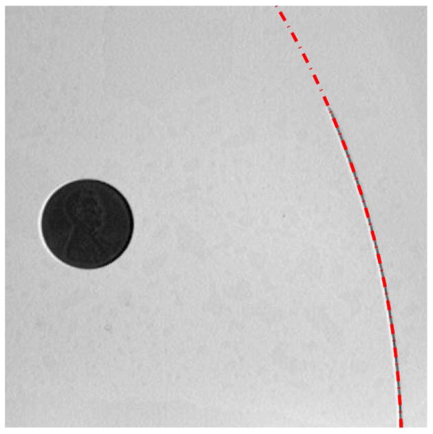
All analyses were conducted in MATLAB (MathWorks, Natick, MA). Upon completion of full needle insertion, the final image captured was digitally subtracted from the initial image for that trial. A binary threshold was applied to create a black and white image and the inserted needle trace was segmented through connected components. The binary pixel silhouette was used to determine the curvature of the needle by fitting a circle to the needle outline. Fitting of a circle to the needle trajectory was performed (Fig. 2), based upon [7]. The radius of the circle that was fit to the needle trajectory (ρ) was used to quantify the curvature (κ = 1/ρ) of each needle, inserted into each tissue type, at each duty cycle. A penny in the field of view was used to scale between pixel and millimeter units (approximately 4.83 pixels/mm).
Figure 2.
Final image of the 0.18 mm radius nitinol wire inserted into Gel B in the 0% duty cycle trial. The red dashed line demonstrates the circle fit to the needle trace (radius of curvature 190.04 mm). The penny in the image (19.05 mm diameter) allows for conversion from pixels to millimeters.
III. Results
A. Curvature, Duty Cycle, and Tissue Stiffness
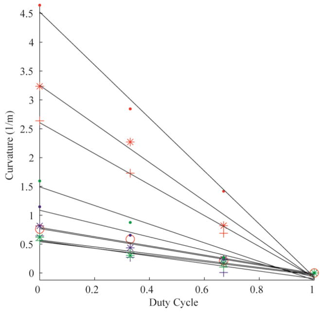
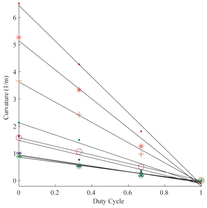
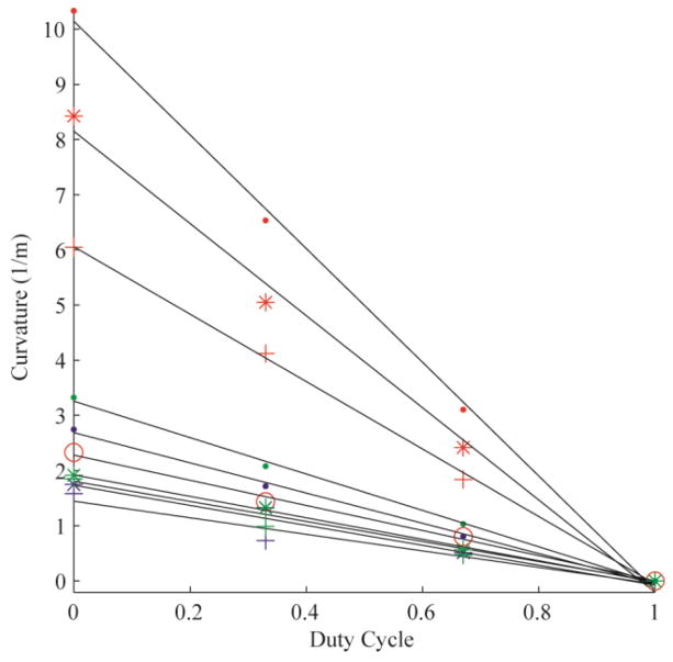
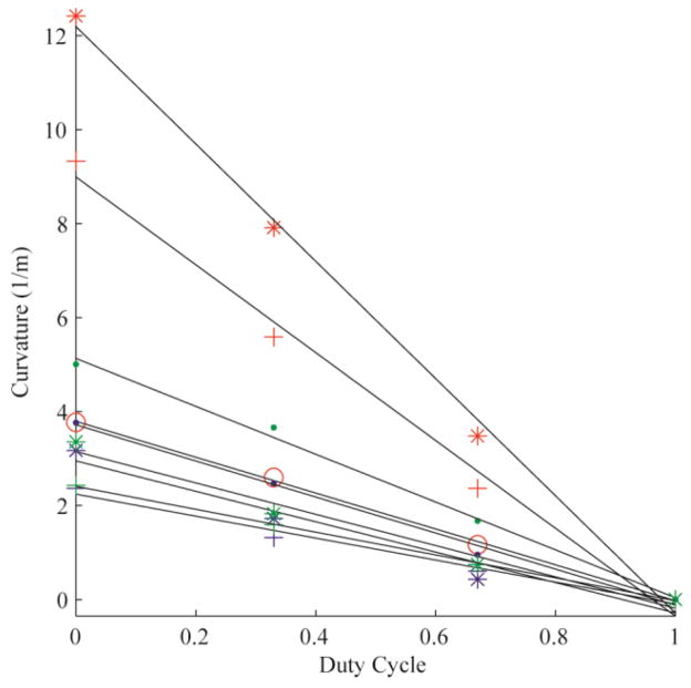
The error of the circle fit was calculated for each trial, yielding an average R2 value of 0.99 (± 0.03). Fig. 3 demonstrates the linear relationships between duty-cycled rotation and curvature for all 10 needles tested in Gel A. Each color represents a needle material (red: nitinol; blue: stainless steel; green: piano wire). The marker styles represent the different radii of each needle material. Fig. 4, Fig. 5 and Fig. 6 are the linear relationships between curvature and duty-cycled rotation for all needles in Gels B, C and D, respectively. Linear regression on curvature vs. duty cycle for all needles in all mediums produced a mean R2 value of 0.98 (±0.02), indicating that the linear relationship holds across tissue type, needle material and needle radius. Note that the 0.13 mm radius nitinol wire could not be accurately inserted into Gel D without the needle bending significantly, so these results were omitted.
Figure 3.
Curvature vs. duty cycle for all 10 needles in Gel A. The colors represent different needle material (red: nitinol; blue: stainless steel; green: piano wire). The marker styles represents the different needle radii for each material, from thinnest to thickest: ‘·’, ‘*’, ‘+’. There are four nitinol needles (as opposed to three for stainless steel and piano wire), thus the thickest nitinol needle is represented by the marker ‘o’.
Figure 4.
Curvature vs. duty cycle for all 10 needles in Gel B, plotted with the same formatting as in Fig. 3.
Figure 5.
Curvature vs. duty cycle for all 10 needles in Gel C, plotted with the same formatting as in Fig. 3.
Figure 6.
Curvature vs. duty cycle for nine needles in Gel D, plotted with the same formatting as in Fig. 3. The 0.13 mm nitinol wire was excluded from this gel due to buckling of the uninserted portion of the needle.
B. Modeling Needle Mechanics
Based upon the result that all needles exhibited a linear relationship between curvature and rotational duty cycle for all values of tissue stiffness, we next sought to develop a simplified model of bevel-tipped needle curvature under duty-cycled control. In order to generalize such a relationship, the properties of the needle curvature were approached from the framework of Euler beam theory. We investigated how close needle curvature is to being proportional to the transverse force applied to the needle tip, and inversely proportional to the flexural rigidity (EnI) of the needle, where I is the second moment of inertia. We assumed for simplicity that the force applied by the tissue onto the needle tip follows a Hooke’s law relationship, in which the stress applied to the bevel surface is proportional to the Young’s modulus of the tissue; the force is then proportional to the bevel surface area, which is proportional to r2, where r is the needle radius. Thus, neglecting other force components such as friction [8], we hypothesized that for certain needles and tissues,
| (1) |
where D is the duty cycle. This is equivalent to neglecting variations in curvature due to the trigonometric functions in the detailed model of transverse force in [8] (which depend on tissue properties and bevel angle).
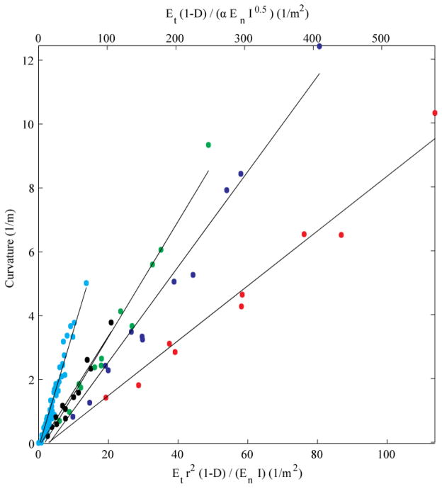
Fig. 7 displays the results of curvature plotted as a function of the right-hand parameters in (1). The curvature for each needle, in each tissue, at each duty cycle is plotted. Based on the linear patterns that were evident in the data, five linear regressions were performed: one for each nitinol needle (red: 0.13 mm; blue: 0.18 mm; green: 0.23 mm; black: 0.35 mm), and one for the composite results for all stainless steel and piano wire needles (cyan). The mean R2 of the linear regressions is 0.97 (± 0.01). The nitinol needles display distinct relationships with respect to (1), while the stainless steel and piano wire needles are close enough to one another to be indistinguishable in the graph.
Figure 7.
Curvature vs. needle and tissue parameters, and duty cycle. Red: 0.13 mm nitinol; blue: 0.18 mm nitinol; green 0.23 mm nitinol; black: 0.35 mm nitinol; cyan: stainless steel and piano wire.
IV. Discussion
Rupture toughness of the tissues was not measured in this study. However, we note that for materials in which rupture toughness, Gc, is roughly proportional to ET (which is not out of the ordinary for gels [9]), then, with the exception of the duty cycle parameter (1-D), the quantity graphed along the upper x-axis in Fig. 5,
where α is the bevel angle, would be proportional to the reciprocal of the dimensionless parameter Π3 in [8], i.e.,
for the Neo-Hookean case in which the hyperelastic material property C10 is proportional to Et, as in [8]. Further analysis of these data is ongoing, particularly in terms of physical interpretation of the relationship between curvature, Young’s modulus of the tissue and needle, and flexural rigidity of the needle.
Our present results have shown that linearity between rotation duty cycle and curvature is maintained over a range of values of needle material stiffness, needle radius, and tissue stiffness. In total, we performed 39 unique combinations of needle and tissue insertions (omitting the 0.13 mm nitinol wire insertion into Gel D due to buckling of the uninserted portion of the needle), each performed at four distinct duty-cycled rates of rotation. Future work includes testing at multiple bevel angles.
Acknowledgments
Research supported by NIH grant no. R21EB012209.
Contributor Information
Craig A. Lehocky, Email: calehocky@cmu.edu, The Department of Biomedical Engineering at Carnegie Mellon University, Pittsburgh, PA 15213 USA (phone: 412-268-2023; fax: 412-268-7350)
Cameron N. Riviere, Email: cam.riviere@cs.cmu.edu, The Robotics Institute, Carnegie Mellon University, Pittsburgh, PA 15213 USA
References
- 1.Abolhassani N, Patel R, Moallem M. Needle insertion into soft tissue: a survey. Med Eng Phys. 2007;29(4):413–431. doi: 10.1016/j.medengphy.2006.07.003. [DOI] [PubMed] [Google Scholar]
- 2.Field M, Witham TF, Flickinger JC, Kondziolka D, Lunsford LD. Comprehensive assessment of hemorrhage risks and outcomes after stereotactic brain biopsy. J Neurosurg. 2001 Apr;94:545–551. doi: 10.3171/jns.2001.94.4.0545. [DOI] [PubMed] [Google Scholar]
- 3.Cowan NJ, Goldberg K, Chirikjian GS, Fichtinger G, Reed KB, Kallem V, Park W, Misra S, Okamura AM. Robotic needle steering: design, modeling, planning, and image guidance. In: Rosen J, Hannaford B, Satava RM, editors. Surgical Robotics: Systems, Applications, and Visions. New York: Springer; 2010. pp. 557–582. [Google Scholar]
- 4.Webster RJ, III, Kim JS, Cowan NJ, Chirikjian GS, Okamura AM. Nonholonomic modeling of needle steering. Int J Robot Res. 2006 May;25(5–6):509–525. [Google Scholar]
- 5.Engh JA, Minhas D, Kondziolka D, Riviere CN. Percutaneous intracerebral navigation by duty-cycled spinning of flexible bevel-tipped needles. Neurosurgery. 2010;67(4):1117–1123. doi: 10.1227/NEU.0b013e3181ec1551. [DOI] [PubMed] [Google Scholar]
- 6.Minhas DS, Engh JA, Fenske MM, Riviere CN. Modeling of needle steering via duty-cycled spinning. Proc Annu Int Conf IEEE Eng Med Biol Soc. 2007:2756–2759. doi: 10.1109/IEMBS.2007.4352899. [DOI] [PubMed] [Google Scholar]
- 7.Taubin G. Estimation of planar curves, surfaces, and nonplanar space-curves defined by implicit equations with applications to edge and range image segmentation. IEEE Trans Pattern Anal Mach Intell. 1991 Nov;13:1115–1138. [Google Scholar]
- 8.Misra S, Reed KB, Schafer BW, Ramesh KT, Okamura AM. Mechanics of flexible needles robotically steered through soft tissue. Int J Robot Res. 2010 Nov;29:1640–1660. doi: 10.1177/0278364910369714. [DOI] [PMC free article] [PubMed] [Google Scholar]
- 9.Darvell BW, Lee PKD, Yuen TDB, Lucas PW. A portable fracture toughness tester for biological materials. Meas Sci Technol. 1996;7:954–962. [Google Scholar]


