Abstract
Medical augmented reality has undergone great development recently. However, there is a lack of studies to compare quantitatively the different display options available. This paper compares the effects of different graphical overlay systems in a simple micromanipulation task with “soft” visual servoing. We compared positioning accuracy in a real-time visually-guided task using Micron, an active handheld tremor-canceling microsurgical instrument, using three different displays: 2D screen, 3D screen, and microscope with monocular image injection. Tested with novices and an experienced vitreoretinal surgeon, display of virtual cues in the microscope via an augmented reality injection system significantly (p < 0.05) decreased 3D error compared to the 2D and 3D monitors when confounding factors such as magnification level were normalized.
I. Introduction
Medical augmented reality addresses the need of overlaying preoperative biomedical imaging data onto the surgical scene so that the surgeons are able to visualize imaging data and the patient within the same space. With this purpose several medical augmented reality technologies have been developed [1]. Preliminary results with surgeons in our laboratory have suggested that viewing the workspace via cameras and computer monitor degrades performance compared to viewing directly through the stereo operating microscope [2]. There have been studies on how the micromanipulation accuracy is affected while performing tasks in microsurgery in different conditions such as posture, visual feedback, grip force, and speed [3–4]. However, there is a general lack of studies that analyze different display methods and their effect on micromanipulation accuracy; evaluation studies of medical augmented reality displays tend to assess only the accuracy of the image registration itself, rather than the accuracy of manipulation enabled by the display [5].
Our goal is to analyze performance of micromanipulation using visual cues presented to the user via a variety of display options while normalizing underlying factors that affect the error, such as human tremor and the level of magnification. This paper compares the accuracy obtained in microsurgical tasks guided by visual control displayed on a 2D screen, on a 3D screen, and in one of the eyepieces of a stereo operating microscope. In order to achieve relevant results, decreasing the effect of human tremor, the tests are run using Micron [6], a handheld micromanipulator that compensates for tremor. Effects of variable magnification between displays are controlled for by normalizing the screen magnification and making it equal to the microscope magnification. Section II covers background material and introduces Micron. Section III depicts the experiment design. In Section IV, we compare the display systems with microsurgical tasks. Finally, we conclude in Section V with a discussion of results and directions for future work.
II. The Micron Robotic System
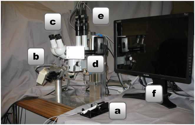
The robotic system used in this research is Micron (Fig. 1), a handheld actively-stabilized tool that increases accuracy in microsurgery or other precision micromanipulation tasks. It removes involuntary motion such as tremor by actuating the tip to counteract the effect of the undesired handle motion [6]. Visual servoing is applied to guide the tip using visual feedback from two Point Grey Flea2 cameras that are mounted to the microscope, providing a stereo view of workspace. Designed for microsurgical work, Micron is operated under a Zeiss® OPMI® 1 microscope. The system uses a custom optical tracking hardware named ASAP, which supplies Micron with the position of its tip in real time [7]. The entire setup can be seen in Fig. 2.
Fig. 1.
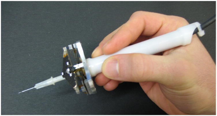
Micron, a handheld micromanipulator.
Fig. 2.
System setup with (a) Micron, (b) ASAP position sensors, (c) surgical microscope, (d) image injection system, (e) stereo cameras, and (f) 3D monitor.
A. Vision-Based Virtual Fixtures
Virtual fixtures are a key to reducing error during microsurgical tasks with Micron. They act to limit error in a manner akin to a ruler that aids in drawing a line. Specifically, represented as a subspace defined in 3D Euclidean space by the stereo pair of cameras, the virtual fixture must constrain the tip position of Micron to lie on the subspace [8]. Two types of virtual fixtures are implemented: hard and soft. In the case of hard virtual fixtures, the tip of Micron should always lie on the subspace representing the fixture; in the case of soft virtual fixtures, the difference between the hand motion and the virtual fixture is scaled by a selectable scale factor. Soft virtual fixtures are used in this research because they are the most practical ones for clinical use, in that they concede some freedom of operation to the surgeon. Fig. 3 graphically depicts how the soft virtual fixtures work.
Fig. 3.
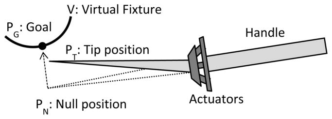
Example of handheld micromanipulation with soft virtual fixtures, which drives the tip position PT to the goal position PG on the virtual fixture V. The tip position is calculated by the orthogonal projection of the null position PN. The null position is the location of the tip position if the actuators were turned off. The error is scaled by a parameter λ ∈ [0,1] which represents the proportion of the movement that is due to the surgeon. (Note: figure not to scale.)
In addition to generating the virtual fixtures, the vision system is responsible for maintaining the adaptive registration by tracking the tip position. Image processing techniques such as thresholding and blob tracking allow the vision system to accurately locate the Micron tip, which is painted with acrylic white paint to facilitate tracking.
B. Image Injection into Microscope Eyepiece
To enhance the operation of Micron by surgeons, certain visual cues and annotations can be helpful. These may include, but are not necessarily limited to, target positions, depth (vertical) error, and traces of tip position history. Conventionally, this information can be displayed on a 2D or 3D monitor by overlaying visual cues on microscope views acquired from the two cameras. However, such overlay on the screen is unfamiliar to surgeons, who are much more accustomed to operating with a microscope. To solve this problem, our laboratory has developed an inexpensive monocular pico-projector-based augmented reality (AR) display for a surgical microscope (Fig. 4). This system enables the injection of overlay images into one of the eyepieces of the microscope [9].
Fig. 4.
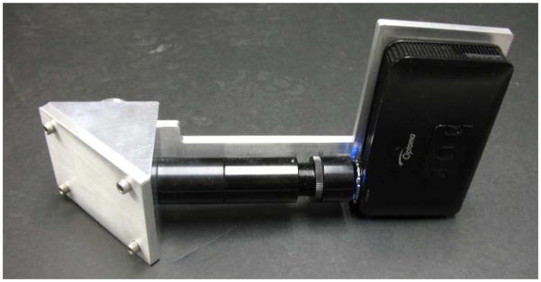
The AR system detached from the surgical microscope.
III. Experimental Methods
To compare the augmented reality microscope display with computer monitor displays, it was necessary to set up the 3D representation, establish a magnification reference, and define a task which requires accuracy on the scale of microns.
A. 3D Monitor Setup
On a traditional monitor screen there is a loss of information inherent in the nature of the 2D image display. A stereo vision system captures two images, thus allowing a 3D reconstruction; therefore a 3D monitor can display depth information. An interface was developed to generate an adequate input for the 3D monitor. Perfect matching of the images is critical to achieve a sharp 3D image. The OpenCV library [10] was used to build the 3D image representation. Three sliders allowed the operator to change in real time the relative horizontal and vertical position as well as the rotation between images.
B. Magnification Normalization
The magnification is an important parameter in the accuracy of microsurgical tasks. To equitably compare different display systems, magnification was normalized. The angular magnification, MA, produced by an optical system is defined as the relative angular size of an image produced by the optical system as compared to the maximum directly-observable size of the object with the unaided eye. For a microscope it can be calculated from the value of the focal length of the binocular tube, fb, the focal length of the objective, fo, the magnification of the eyepiece, me, and the magnification factor of the magnification changer, mf.
| (1) |
For real images, such as those on a screen, the linear magnification is defined by the ratio between the height of the object ho and the height of the image hi. However, one must take into account the distance between the screen and the eye. To normalize the screen magnification and microscope amplification, a constant 25 cm is used as an estimation of the “near point” distance of the eye, the closest distance at which the healthy naked eye can focus. The normalized angular magnification for a screen, where is the distance in centimeters from the screen to the eyes, is:
| (2) |
C. Circle Tracing Trial
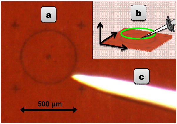
A good trial for evaluating display accuracy must require not only accuracy in the plane but also precision in depth. We selected the task of tracing a circle 500 μm in diameter three times, holding the tip of the instrument 500 μm above a rubber surface. A 3D circle fixture derived from the tracked rubber target was used (Fig. 5). An important consideration is that the virtual fixtures can disrupt the eye-hand coordination feedback loop. In order to prevent unbounded drifting behavior, we display visual cues that indicate the 3D location of the unseen null position of the tip manipulator of Micron [8]. As shown in Fig. 6, we choose visual cues in the form of two circles: a green one to show the goal location and a blue one to show the null position, which reflects actual hand movement. The distance between the circle centers represents the planar error Micron is currently eliminating. Depth error is displayed by varying the radius of the null position circle, e.g., a growing radius represents upwards drift. The operator is instructed to keep the two circles roughly coincident, in order to avoid drift, which causes low-frequency error and eventually saturates the actuators.
Fig. 5.
(a) Circular target, 500 μm in diameter, on a rubber surface. (b) Generating a 3D circle virtual fixture from the tracked target. (c) White-painted, tapered tip of Micron.
Fig. 6.

Circle-tracing task with visual cues: green represents the goal, blue the null position of the manipulator. (a) Coincidence of the circles is the desired condition, indicating Micron is near the center of its range of motion. (b) The position and size of the blue circle indicate the planar and depth error, respectively.
D. Experimental Procedure
Several experiments were performed with Micron to compare the different display systems and the influence of the magnification. Three scenarios were tested: 2D monitor, 3D monitor, and image injection system. Binoculars with a magnification of 35.7x were used (fb = 125 mm, fo = 175 mm, me = 20.0 and mf = 2.5). The distance from the screen in the 2D and 3D monitor scenarios was set to 56 cm in order to normalize the magnification. The window size used for the image displayed on the screen was set to 424×273 pixels, such that the target circle (Fig. 5(a)) appeared 40 mm in diameter.
A λ=1/3 scale factor was used; therefore all hand motions that deviated from the virtual fixture were scaled by one third. The tremor error is significantly decreased, but the control is shared between the virtual fixture and the operator, allowing the experiment to evaluate which scenario performs best under approximately tremor-free manipulation.
Two different scenarios were tested to make a complete analysis of the accuracy using each display method. In the first scenario, three different novice operators executed the task eight times for each display system. In the second scenario, an experienced ophthalmic surgeon performed the task 12 times for each scenario. In all cases, one set of experiments were performed and discarded to allow the subject to adjust to the Micron and the task while minimizing the effects of any learning curve. Experiments were performed in random order to alleviate ordering effects. Error was measured as the Euclidean distance between the tip position provided by the ASAP optical trackers and the closest point of the virtual fixture, generated by the registered stereo cameras. Data were recorded at 2 kHz.
IV. Results
Figs. 7 and 8 present 3D mean RMS (Root Mean Squared) error and average maximum 3D error respectively for the first scenario. The standard deviation is also displayed. Both the RMS error and the maximum error with the image injection are significantly lower than the errors obtained with either the 2D or 3D monitor displays. Statistical significance is assessed with a two-tailed T-test (p < 0.05) and marked with an asterisk (*).
Fig. 7.
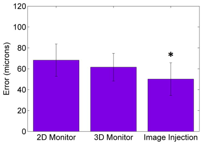
Novices’ mean 3D RMS error with error bars for standard deviation, across 24 trials with each display. Image injection significantly reduces error compared to 2D and 3D monitor (p < 0.05).
Fig. 8.
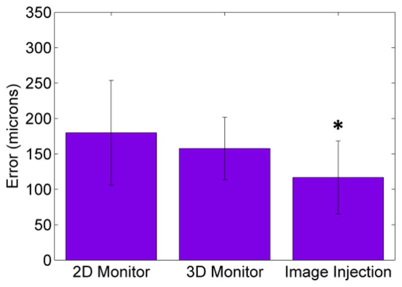
Novices’ maximum 3D error with error bars for standard deviation, across 24 trials with each display. Image injection significantly reduces error compared to 2D and 3D monitor (p < 0.05).
In Figs. 9–10, the 3D mean RMS error and maximum 3D error with standard deviation are shown for the surgeon trials. In this case the differences are larger between scenarios. The results of this experiment show that the 3D monitor fails as an enhanced alternative to the 2D monitor and also confirms the image injection system as the best display system for visual feedback (p < 0.05).
Fig. 9.
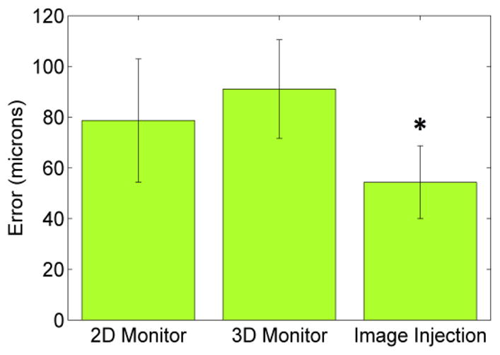
Surgeon’s mean 3D error with error bars for standard deviation, across 12 trials with each display. Image injection significantly reduces error compared to 2D and 3D monitor (p < 0.05).
Fig. 10.
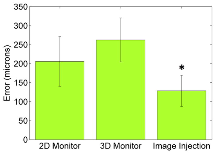
Surgeon’s maximum 3D error with error bars for standard deviation, across 12 trials with each display. Image injection significantly reduces error compared to 2D and 3D monitor (p < 0.05).
V. Discussion
These preliminary results suggest that visual cues displayed via monocular augmented reality display within the surgical microscope enable more accurate micromanipulation than visual cues displayed on 2D or 3D monitors, in that both mean and maximum error are reduced, both for novices and for an experienced surgeon. This is likely due to the higher image quality and decreased latency of the microscope. The augmented reality display also allows the system to overlay biomedical imaging data or other helpful visual information directly into the microscope. Future work includes testing different virtual fixtures and evaluating in more realistic surgical procedures.
Acknowledgments
This work was supported in part by the U.S. National Institutes of Health under grants R01EB000526 and R01EB007969, and by the University of Valladolid, Spain.
Contributor Information
Santiago Rodríguez Palma, University of Valladolid, Valladolid, Spain.
Brian C. Becker, Robotics Institute, Carnegie Mellon University, Pittsburgh, PA 15213 USA
Louis A. Lobes, Jr., Department of Ophthalmology, University of Pittsburgh Medical Center, Pittsburgh, PA 15213 USA
Cameron N. Riviere, Email: camr@ri.cmu.edu, Robotics Institute, Carnegie Mellon University, Pittsburgh, PA 15213 USA
References
- 1.Sielhorst T, Feuerstein M, Navab N. Advanced medical displays, a literature review of augmented reality. J Display Technol. 2008 Dec;4:451–467. [Google Scholar]
- 2.Becker BC, Voros S, Lobes LA, Jr, Hager GD, Riviere CN. Semiautomated intraocular laser surgery using handheld instruments. Lasers Surg Med. 2010 Mar;42:264–273. doi: 10.1002/lsm.20897. [DOI] [PMC free article] [PubMed] [Google Scholar]
- 3.Safwat B, Su ELM, Gassert R, Teo CL, Burdet E. The role of posture, magnification, and grip force on microscopic accuracy. Ann Biomed Eng. 2009 May;37:997–1006. doi: 10.1007/s10439-009-9664-7. [DOI] [PubMed] [Google Scholar]
- 4.Ananda ES, Latt WT, Shee CY, Su ELM, Burdet E, Lim TC, Teo CL, Ang WT. Influence of visual feedback and speed on micromanipulation accuracy. Proc Annu Int Conf IEEE Eng Med Biol Soc. 2009:1188–1191. doi: 10.1109/IEMBS.2009.5333996. [DOI] [PubMed] [Google Scholar]
- 5.Edwards PJ, King AP, Maurer CR, Jr, de Cunha DA, Hawkes DJ, Hill DL, Gaston RP, Fenlon MR, Jusczyzck A, Strong AJ, Chandler CL, Gleeson MJ. Design and evaluation of a system for microscope-assisted guided interventions (MAGI) IEEE Trans Med Imaging. 2000 Nov;19(11):1082–1093. doi: 10.1109/42.896784. [DOI] [PubMed] [Google Scholar]
- 6.MacLachlan RA, Becker BC, Podnar GW, Cuevas Tabarés J, Lobes LA, Riviere CN. Micron: an actively stabilized handheld tool for microsurgery. IEEE Trans Robot. 2012;28(1):195–212. doi: 10.1109/TRO.2011.2169634. [DOI] [PMC free article] [PubMed] [Google Scholar]
- 7.MacLachlan RA, Riviere CN. High-speed microscale optical tracking using digital frequency-domain multiplexing. IEEE Trans Instrum Meas. 2009;58(6):1991–2001. doi: 10.1109/TIM.2008.2006132. [DOI] [PMC free article] [PubMed] [Google Scholar]
- 8.Becker BC, MacLachlan RA, Hager GD, Riviere CN. Handheld micromanipulation with vision-based virtual fixtures. Proc IEEE Int Conf Robot Autom. 2011:4127–4132. doi: 10.1109/ICRA.2011.5980345. [DOI] [PMC free article] [PubMed] [Google Scholar]
- 9.Shi C, Becker BC, Riviere CN. Inexpensive monocular pico-projector-based augmented reality display for surgical microscope. Proc. 25th IEEE Int. Symp. Computer-Based Medical Systems; 2012. accepted for publication. [DOI] [PMC free article] [PubMed] [Google Scholar]
- 10.OpenCV Library. Available: http://opencv.willowgarage.com/


