Abstract
An active handheld micromanipulator has been developed that is capable of automated intraocular acquisition of B-mode and C-mode optical coherence tomography scans that are up to 4 mm wide. The manipulator is a handheld Gough-Stewart platform actuated by ultrasonic linear motors. The manipulator has been equipped with a Fourier-domain common-path intraocular OCT probe that fits within a 25-gauge needle. The paper describes the systems and techniques involved, and presents preliminary results of B-mode and C-mode scans.
I. Introduction
Optical coherence tomography (OCT) has become an important tool for ophthalmology in recent years [1]. Its importance was originally due to the confocal scanning laser ophthalmoscope, which images the retina from outside the eye [2], and which was later improved with adaptive optics to correct for natural aberrations in the eye [3]. More recently, intraocular OCT probes for surgical use have appeared [4].
B-mode and C-mode scans can be generated by tracking the position of a probe as it moves across tissue. Such a scan can be performed manually [5–7]. However, the accuracy and repeatability of robotic devices provide a clear advantage for acquisition of such scans. Furthermore, with an actuated device, the distance of the probe from the tissue can be automatically controlled, which is beneficial both for safety and for image quality [8]. Spiral-scanning devices have been developed for endoscopic use [9–11]. Helical scans have been used for imaging luminal organs such as the esophagus [12]. Robotic B-mode and C-mode scanning has been demonstrated also for intraocular applications, using the Johns Hopkins Eye Robot [7, 13].
A fully-handheld microsurgical robot, known as Micron, has been developed [14]. It is capable of stabilizing its tool tip by sensing hand motion and actively compensating the erroneous component. The handheld approach sacrifices a certain amount of steadiness or accuracy in comparison with table-mounted robotic arms [15–17], but possesses certain advantages in terms of ease of use and low cost. Previous prototypes of Micron featured 3 degrees of freedom (DOF) and had a range of tip motion of less than 1 millimeter [14], but a new prototype has recently been developed, with 6 DOF and a greatly increased range of motion [18], largely in order to better perform scanning for applications such as intraocular OCT sensing and laser photocoagulation [19]. This paper describes B-mode and C-mode OCT scanning techniques using Micron, and presents preliminary results.
II. Methods
A. Scanning System
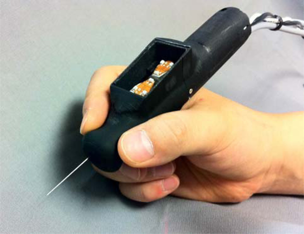
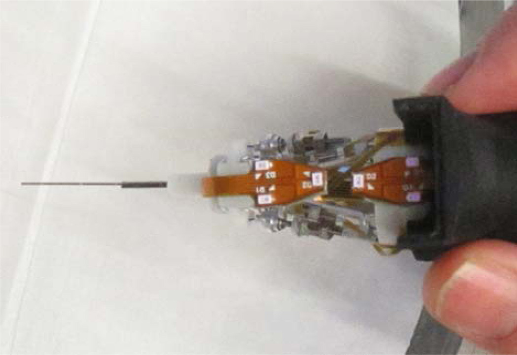
The active handheld micromanipulator, Micron (Fig. 1), incorporates a Gough-Stewart platform actuated by six ultrasonic linear motors (SQUIGGLE® SQL-RV-1.8, New Scale Technologies, Inc., USA) (Fig. 2). The manipulator workspace, defined for the tip of the intraocular tool shaft, is designed to include a cylinder 4 mm in diameter and 4 mm high. Under closed-loop control, the system has a −3 dB bandwidth of approximately 40 Hz. The system can withstand a transverse load of up to 0.2 N at the point of the sclerotomy (the entry point through the white of the eye), 20 mm from the tip of the intraocular shaft, without degradation of performance. The maximum diameter of the instrument is 27.5 mm, and the instrument is 130 mm long, excluding the intraocular shaft which protrudes from the housing (Fig. 1). The instrument can be fitted with a variety of end-effectors. To date, passive tools such as picks, micropipettes, and optical fibers have been used, but actuated tools such as forceps would also be possible.
Figure 1.
Micron, an active handheld micromanipulator.
Figure 2.
View of Micron with the front housing removed for easier viewing of the six LEDs (white rectangles) and the actuators.
Position sensing for feedback control was provided by a custom-built microscale optical tracking system, ASAP (Apparatus to Sense Accuracy of Position) [20]. For the new 6DOF prototype of Micron, six infrared LEDs to be tracked were affixed: three to the manipulator, and three to the handle (Fig. 2). The LEDs are detected by two position-sensitive detectors (PSDs) at a sampling rate of 1 kHz. ASAP provides 6DOF tracking of both the manipulator and the handle of Micron throughout a workspace of roughly 27 cm3, with less than 6 µm RMS error. During a scan, the control system of Micron actively compensates tremor and any other hand motion, the intention being to allow no motion of the tip other than the specified scan.
This study used the endoscopic Fourier-domain common-path OCT system of Liu et al. [21], which works on the principle that interference of coherent light with itself after it is reflected and refracted encodes, in the Fourier domain, the distances from the reference plane to the optically opaque layers of the imaged sample. The system is driven by an 840-nm superluminescent diode (SLED) with spectral width of 50nm. Using a custom-built spectrometer, the system features a theoretical axial resolution of 6.2 µm and a practical imaging range of approximately 3 mm in air. The probe consists of standard single-mode fiber, with 9-µm core, 125-µm cladding, and an outer coating 245 µm in diameter, bonded within a 25-Ga. hypodermic needle. Including image digitization and signal processing, the system sampling rate is approximately 4.5 kHz for single axial images (A-scans) with minimal latency. Image integration time is 10µs. B-mode and C-mode scans were composed of position-tracked A-mode scans using the 6DOF pose information from the same optical tracker used for feedback control of Micron, running at a 1 kHz update rate.
The OCT image data acquired from the probe is sent to a visualization workstation via Ethernet. Both applications are developed using the cisst-saw open source C++ framework (http://www.cisst.org/cisst/saw/).
B. Testing
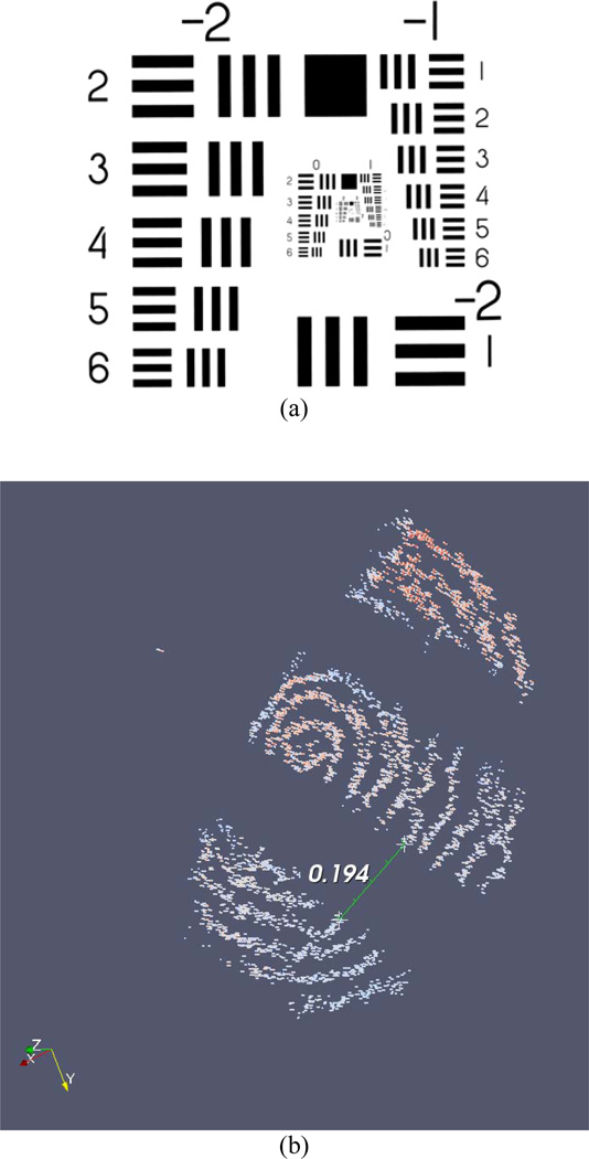
Two handheld tests of scanning performance were conducted. The first test of the system was a spiral C-mode scan of group 1, element 4, from a USAF 1951 MIL-STD-150A resolution test chart (Fig. 3(a); group 1, element 4 is slightly right of center). The probe tip speed along the spiral trajectory was set at 2 mm/s. The commanded spacing between adjacent cycles of the spiral was 50 µm. The total diameter of the scanned spiral was 1 mm. Because the OCT system sampling rate is higher than the sampling rate of ASAP, linear interpolation between measured poses of the probe was used to estimate the pose corresponding to each OCT A-mode scan or “data point.”
Figure 3.
(a) USAF 1951 MIL-STD-150A resolution test chart. (b) Result of spiral C-mode scan of USAF 1951 MIL-STD-150A resolution test chart, group 1, element 4 (the fourth element below the number “1,” slightly right of center in (a)). The three bars from the element in the chart (which are black in the original chart) are visible in the scan. The space between bars, which measures 0.176 mm on the chart, is measured at 0.194 mm in the acquired scan.
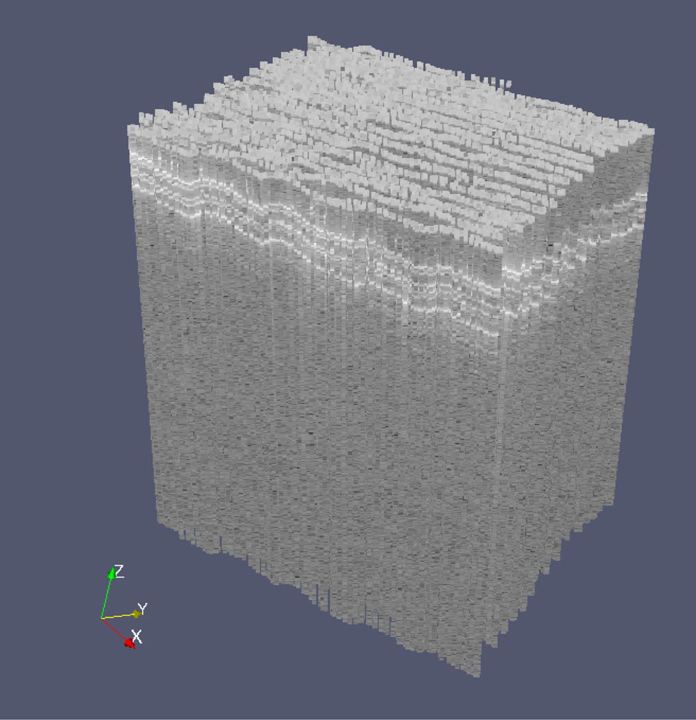
The second demonstration of performance was a repeated B-mode scan. The manipulator oscillated the probe in a triangular wave pattern at 5 Hz. The motion of the tip of the probe was 3 mm peak-to-peak at a speed of 30 mm/s. During execution, the tool was moved manually in the direction perpendicular to the B-mode scan, resulting in a zigzag scan pattern with a total of 50 scan lines. The scanned material in this case was a stack of 3 layers of 3M™ Polyester Tape 8911. Each layer is 50 µm thick (30 µm adhesive and 20 µm backing).
III. Results
The result of the spiral C-mode scan is shown in Fig. 3(b). A false-color representation and thresholding were used to aid visualization. The spiral contains 17862 individual A-mode scans. This included 7917 poses measured by ASAP; hence, the scan time was 7.9 s. The space between bars in the scanned image was estimated using a drawing widget in the visualization software. The space between bars, which measures 0.176 mm on the chart, is measured at 0.194 mm in the acquired scan.
The result of the zigzag B-mode scan is shown in Fig. 4. The three layers of the tape can be clearly seen near the top of the scanned volume. The total pattern contains 11272 individual A-mode scans. This included 5045 poses measured by ASAP; the scan time was 5.0 s.
Figure 4.
Result of zigzag B-mode scan of a stack of 3 layers of 3M™ Polyester Tape 8911 (each layer is 50 µm thick). B-mode scanning was performed automatically, while movement in the perpendicular direction to generate the zigzag was performed manually. The 3 layers are evident near the top of the scanned volume.
IV. Discussion
The data presented indicate the general feasibility of acquiring surgically useful OCT scans in B-mode and C-mode using the 6-DOF Micron. This new Micron prototype possesses advantages for size and quality of OCT scans compared to the previous 3-DOF Micron [14], since the 6-DOF Micron has a far larger range of motion and provides for a remote center of motion at the sclerotomy. Future work will involve refinement of the control system for improved scanning speed and accuracy.
Acknowledgments
Research supported by the U.S. National Institutes of Health (grant nos. R01EB007969 and R01EB000526) and the Kwanjeong Educational Foundation.
Contributor Information
Sungwook Yang, Robotics Institute, Carnegie Mellon University, Pittsburgh, PA 15213 USA.
Marcin Balicki, Department of Computer Science, Johns Hopkins University, Baltimore, MD 21218 USA.
Robert A. MacLachlan, Robotics Institute, Carnegie Mellon University, Pittsburgh, PA 15213 USA
Xuan Liu, Department of Electrical and Computer Engineering, Johns Hopkins University, Baltimore, MD 21218 USA.
Jin U. Kang, Department of Electrical and Computer Engineering, Johns Hopkins University, Baltimore, MD 21218 USA
Russell H. Taylor, Department of Computer Science, Johns Hopkins University, Baltimore, MD 21218 USA
Cameron N. Riviere, Email: camr@ri.cmu.edu, Robotics Institute, Carnegie Mellon University, Pittsburgh, PA 15213 USA.
References
- 1.Kang JU, Han J-H, Liu X, Zhang K, Song CG, Gehlbach P. Endoscopic functional Fourier domain common-path optical coherence tomography for microsurgery. IEEE J. Sel. Topics Quantum Electron. 2010;vol. 16:781–792. doi: 10.1109/jstqe.2009.2031597. [DOI] [PMC free article] [PubMed] [Google Scholar]
- 2.Webb RH, Hughes GW, Delori FC. Confocal scanning laser ophthalmoscope. Applied Optics. 1987;vol. 26:1492–1499. doi: 10.1364/AO.26.001492. [DOI] [PubMed] [Google Scholar]
- 3.Roorda A, Romero-Borja F, Donnelly WJ, III, Queener H, Hebert TJ, Campbell MCW. Adaptive optics scanning laser ophthalmoscopy. Optics Express. 2002;vol. 10:405–412. doi: 10.1364/oe.10.000405. [DOI] [PubMed] [Google Scholar]
- 4.Han S, Sarunic MV, Wu J, Humayun M, Yang C. Handheld forward-imaging needle endoscope for ophthalmic optical coherence tomography inspection. J Biomed. Opt. 2008;vol. 13:20505. doi: 10.1117/1.2904664. [DOI] [PubMed] [Google Scholar]
- 5.Ren J, Wu J, McDowell EJ, Yang C. Manual-scanning optical coherence tomography probe based on position tracking. Optics Letters. 2009;vol. 34:3400–3402. doi: 10.1364/OL.34.003400. [DOI] [PubMed] [Google Scholar]
- 6.Ahmad A, Adie SG, Chaney EJ, Sharma U, Boppart SA. Cross-correlation-based image acquisition technique for manually-scanned optical coherence tomography. Optics Express. 2009;vol. 17:8125–8136. doi: 10.1364/oe.17.008125. [DOI] [PMC free article] [PubMed] [Google Scholar]
- 7.Balicki M, Han J-H, Iordachita I, Gehlbach P, Handa J, Taylor R, Kang J. Single fiber optical coherence tomography microsurgical instruments for computer and robot-assisted retinal surgery. Lect. Notes Comput. Sci. 2009;vol. 5761:108–115. doi: 10.1007/978-3-642-04268-3_14. [DOI] [PubMed] [Google Scholar]
- 8.Zhang K, Wang W, Han J, Kang JU. A surface topology and motion compensation system for microsurgery guidance and intervention based on common-path optical coherence tomography. IEEE Trans. Biomed. Eng. 2009;vol. 56:2318–2321. doi: 10.1109/TBME.2009.2024077. [DOI] [PMC free article] [PubMed] [Google Scholar]
- 9.Seibel EJ, Smithwick QYJ. Unique features of optical scanning, single fiber endoscopy. Lasers Surg. Med. 2002;vol. 30:177–183. doi: 10.1002/lsm.10029. [DOI] [PubMed] [Google Scholar]
- 10.Seibel EJ, Brown CM, Dominitz JA, Kimmey MB. Scanning single fiber endoscopy: a new platform technology for integrated laser imaging, diagnosis, and future therapies. Gastrointest. Endosc. Clin. N. Am. 2008;vol. 18:467–478. doi: 10.1016/j.giec.2008.05.001. [DOI] [PMC free article] [PubMed] [Google Scholar]
- 11.Moon S, Lee S-W, Rubinstein M, Wong BJF, Chen Z. Semi-resonant operation of a fiber-cantilever piezotube scanner for stable optical coherence tomography endoscope imaging. Optics Express. 2010;vol. 18:21183–21197. doi: 10.1364/OE.18.021183. [DOI] [PMC free article] [PubMed] [Google Scholar]
- 12.Chen Y, Aguirre AD, Hsiung P-L, Desai S, Herz PR, Pedrosa M, Huang Q, Figueiredo M, Huang S-W, Koski A, Schmitt JM, Fujimoto JG, Mashimo H. Ultrahigh resolution optical coherence tomography of Barrett's esophagus: preliminary descriptive clinical study correlating images with histology. Endoscopy. 2007;vol. 39:599–605. doi: 10.1055/s-2007-966648. [DOI] [PubMed] [Google Scholar]
- 13.Liu X, Balicki M, Taylor RH, Kang JU. Towards automatic calibration of Fourier-domain OCT for robot-assisted vitreoretinal surgery. Optics Express. 2010;vol. 18:24331–24343. doi: 10.1364/OE.18.024331. [DOI] [PMC free article] [PubMed] [Google Scholar]
- 14.MacLachlan RA, Becker BC, Cuevas Tabarés J, Podnar GW, Lobes LA, Jr, Riviere CN. Micron: an actively stabilized handheld tool for microsurgery. IEEE Trans. Robot. 2012;vol. 28:195–212. doi: 10.1109/TRO.2011.2169634. [DOI] [PMC free article] [PubMed] [Google Scholar]
- 15.Üneri A, Balicki MA, Handa J, Gehlbach P, Taylor RH, Iordachita I. New steady-hand Eye Robot with micro-force sensing for vitreoretinal surgery. Proc. IEEE Int. Conf. Biomed. Robot. Biomechatron. 2010:814–819. doi: 10.1109/BIOROB.2010.5625991. [DOI] [PMC free article] [PubMed] [Google Scholar]
- 16.Taylor R, Jensen P, Whitcomb L, Barnes A, Kumar R, Stoianovici D, Gupta P, Wang Z, de Juan E, Jr, Kavoussi L. A steady-hand robotic system for microsurgical augmentation. Int. J. Robot. Res. 1999;vol. 18:1201–1210. [Google Scholar]
- 17.Le Roux PD, Das H, Esquenazi S, Kelly PJ. Robot-assisted microsurgery: a feasibility study in the rat. Neurosurgery. 2001;vol. 48:584–589. doi: 10.1097/00006123-200103000-00026. [DOI] [PubMed] [Google Scholar]
- 18.Yang S, MacLachlan RA, Riviere CN. Design and analysis of 6 DOF handheld micromanipulator. Proc. IEEE Int. Conf. Robot. Autom. 2012:1946–1951. doi: 10.1109/ICRA.2012.6225133. [DOI] [PMC free article] [PubMed] [Google Scholar]
- 19.Becker BC, MacLachlan RA, Lobes LA, Jr, Riviere CN. Semiautomated intraocular laser surgery using handheld instruments. Lasers Surg. Med. 2010;vol. 42:264–273. doi: 10.1002/lsm.20897. [DOI] [PMC free article] [PubMed] [Google Scholar]
- 20.MacLachlan RA, Riviere CN. High-speed microscale optical tracking using digital frequency-domain multiplexing. IEEE Trans. Instrum. Meas. 2009;vol. 58:1991–2001. doi: 10.1109/TIM.2008.2006132. [DOI] [PMC free article] [PubMed] [Google Scholar]
- 21.Liu X, Li X, Kim D, Ilev I, Kang JU. Fiber-optic Fourier-domain common-path OCT. Chin. Opt. Lett. 2008;vol. 6:899–901. [Google Scholar]


