Abstract
Two new series of aggregation-induced emission (AIE) fluorophore-containing amphiphilic copolymers possessing the segments of a monomeric AIE fluorophore, N-(2-hydroxypropyl)methacrylamide (HPMA), [2-(methacryloyloxy)ethyl]trimethylammonium chloride (MATMA), and/or 2,2,2-trifluoroethyl methacrylate (TFEMA) were synthesized. Photophysical properties were investigated using UV-Vis absorbance and fluorescence spectrofluorometry. The increases of molar fractions of the hydrophobic AIE fluorophores and/or the trifluoroethyl moieties result in the higher quantum yields of the AIE fluorophores in the polymers. Using 1-mol% of AIE fluorophores with the tuning of molar fractions of TFEMA, 40% quantum yield was achieved, whereas only less than 10% quantum yield was obtained for the polymers without the TFEMA segments. The quantum yield difference indicates the importance of the fluorine segments for getting high quantum yields of the AIE fluorophores. These polymers were explored for fluorescent bioimaging using human brain glioblastoma U87MG and human esophagus premalignant CP-A cell lines. All the polymers are cell permeable and located in the cellular cytoplasma area. Cellular uptake was demonstrated to be through endocytosis, which is time and energy dependent. The polymers are non-cytotoxic to the two cell lines. Because the polymers contain 19F segments, we studied the spin-lattice relaxation time (T1) and spin-spin relaxation time (T2) of these polymers. T1 and T2 are the two important parameters for the evaluations of the capacity of these polymers for further applications in 19F magnetic resonance imaging (19F MRI). Structure influence on T1 and T2, especially for T2, was observed. These new multifunctional materials are the first series of fluorinated polymers with AIE fluorophores for bioapplications.
Introduction
Development of highly efficient fluorescent materials for electroluminescent devices,1 optical sensors,2 and bioimaging3 has caused significant scientific interests. Among these applications, the technology of fluorescence-based optical bioimaging provides a direct visual tool for observing biological processes and for clinical imaging.3 Typical fluorescent probes include but are not limited to fluorescein derivatives, rhodamines, cyanine derivatives, quantum dots,4 indocyanine greens (ICGs),5 up-conversion nanoparticles,6 and two-photon absorbing materials.7 However, most of these probes suffer a common problem. If the fluorophore concentration is too high, many of the above mentioned fluorescent probes tend to form aggregates, causing aggregation-induced quenching (AIQ), which reduces fluorescence intensity.8 This AIQ effect impedes the performance for bioimaging.
Recently, a new category of fluorophores with the opposite characteristics to the AIQ, aggregation-induced emission (AIE), has been developed.9 AIE fluorophores have been shown to have high fluorescence quantum yields in the aggregate states.10 Restricted intramolecular rotation has been suggested as the possible mechanism of the AIE phenomenon, considering that intramolecular rotations can drastically affect the radiative/nonradiative recombination processes of the excited state. In addition to small-molecule fluorophores, several polymers were also studied to exhibit the AIE effect.10d The AIE effects of these polymers are thought to be caused by the restriction of intramolecular rotations by the aggregate formation.10d In the biological research fields, the AIE fluorophores have been widely explored as sensors for DNA,11 heparin,12 ATP,13 pH,14 CO2,15 and glucose.16 Fewer studies were reported about the applications of the AIE fluorophores as bioimaging probes.17 This is mainly because that most of the AIE fluorophores are hydrophobic. Chemical modification of the AIE fluorophores with polar functional groups can improve their solubility/dispersion in aqueous media, but most of these chemical modifications not only require complicated synthetic procedures, but also sometimes lower the fluorescence quantum yields due to quenching of their excited states by water and nonradiative decay of the excited dyes in aqueous media.18 Some approaches have been used to alleviate these problems and enable the use of the AIE fluorophores for bioimgaing. Nanoparticles including organically modified silica nanoparticles17a–c and amphiphilic block copolymers based micelles17d,e were utilized as nanocarriers to deliver the hydrophobic AIE probes into cells. Besides the physical incorporation of the hydrophobic AIE fluorophores into the nanoparticles, AIE fluorophores were chemically conjugated to silica nanoparticles17c and hydrophilic glycol chitosan for bioimaging.17d Previously, we reported a series AIE-fluorophore-containing random copolymers of poly(N-(2-hydroxypropyl) methacrylamide)-co-poly(2-aminoethyl methacrylate)-co-poly[4-[6-[4-(2-{10-[2-(4-hexyloxy-phenyl)-vinyl]-anthracen-9-yl}-vinyl)-phenoxy]-hexyloxymethyl] styrene]s.19 The quantum yields of the AIE fluorophores in this series of polymers were smaller than 12%.19 Herein, we aim to achieve high quantum yields of the AIE fluorophores in the random copolymer systems. We hypothesize that if hydrophobic segments (herein we use 2,2,2-trifluoroethyl methacrylate (TFEMA)) are introduced into the polymers, the polymers will form micelles with the fluorine-containing segments as the hydrophobic cores and the hydrophobic cores will facilitate the aggregations of AIE fluorophores to achieve high quantum yields.
On the other hand, the 19F segments are the critical elements for 19F magnetic resonance imaging (MRI). Optimal agents for 19F MRI applications should possess: (i) chemical stability, (ii) a simple 19F NMR spectrum, ideally having a single and narrow resonance to maximize sensitivity, and (iii) reasonable 19F spin-lattice relaxation time (T1) and spin–spin relaxation time (T2) to minimize data acquisition time and to improve imaging contrast.20, 21 A variety of fluorinated polymers have been studied as 19F MRI imaging agents. For example, Du et al.22 reported some partially fluorinated hyperbranched copolymers, exhibiting T1 and T2 of the fluorine nuclei of 500 and 50 ms, respectively. Ogawa et al.23 reported fluorinated polymer nanoparticles (polyamidoamine dendrimer-graft-poly(2,2,3,3-tetrafluoropropyl methacrylate)-block-poly(carboxybetaine), PAMAM-g-PTFPMA-b-PCMB), showing T1 and T2 of 250 ms and 10 ms, respectively. Very recently, Thurecht et al.24 reported a series of a hyperbranched fluorinated copolymer (poly(dimethylaminoethyl acrylate)-co-poly(trifluoroethyl acrylate), PDMAEA-stat-PTFEA) showing T2 of 68 ms. This polymer showed the highest 19F MRI sensitivity among the reported 19F materials and was demonstrated to be applicable for in vivo small animal imaging using 19F MRI.
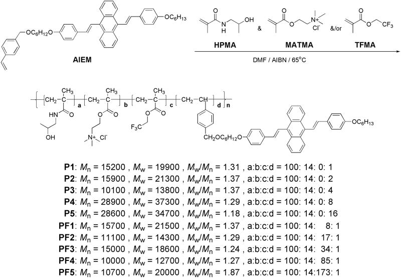
Herein, two new series of AIE fluorophore-containing random copolymers, possessing the segments of a monomeric AIE fluorophore (AIEM, Scheme 1), N-(2-hydroxypropyl)methacrylamide (HPMA), [2-(methacryloyloxy)ethyl]trimethylammonium chloride (MATMA), and/or 2,2,2-trifluoroethyl methacrylate (TFEMA), were prepared and investigated. Poly(N-(2-hydroxypropyl)methacrylamide) (PHPMA) is a non-toxic biopolymer and has been used for drug delivery.25 The use of the MATMA is to enhance cellular uptake of the polymers by using positively charged or cationic amine groups.26 Poly(2,2,2-trifluoroethyl methacrylate) (PTFEMA) will provide the hydrophobic environment in the copolymers to facilitate the aggregations of the AIE fluorophores to achieve high quantum yields. Through the tuning of the polymer structures with adjustable AIE fluorophores or TFEMA fractions, the AIE aggregation phenomenon will be investigated. Besides the studies of AIE phenomena of the polymers, we also aim to develop new biocompatible AIE-containing polymers with high quantum yields. Also the integration of 19F moieties with the AIE fluorophores will further broaden the application of the AIE-containing materials not only for fluorescence imaging but also for 19F magnetic resonance imaging. We expect that the AIE fluorophores can alleviate the common AIQ problems of the widely studied organic fluorophores.
Scheme 1.
Synthesis of AIE fluorophore-containing amphiphilic copolymers.
2. Experimental
2.1. Materials and reagents
All chemicals and solvents were of analytical grade and were used without further purification. Tetrahydrofuran (THF), N,N′-dimethylformamide (DMF), dimethyl sulfoxide (DMSO), azobisisobutyronitrile (AIBN), [2-(methacryloyloxy)ethyl]trimethylammonium chloride (MATMA), 2,2,2-trifluoroethyl methacrylate (TFEMA), and 4-(2-hydroxyethyl)-1-piperazineethanesulfonic acid (HEPES) were commercially available from Sigma-Aldrich (St. Louis, MO). Monomer HPMA was prepared according to the known procedure.25 AIEM was synthesized according to published procedure.19 3-(4,5-Dimethyl thiazol-2-yl)-2,5-diphenyltetrazolium bromide (MTT) assay was purchased from Promega (Madison, WI). Eagle’s minimum essential medium (EMEM) and Keratinocyte medium were purchased from Invitrogen (Carlsbad, CA). EMEM was used for U87 cell culture. Keratinocyte medium was used for CP-A cell culture.
2.2. Instruments
1H NMR and 19F NMR spectra were recorded on a Varian liquid-state 400 NMR spectrometer. Tetramethylsilane (TMS) was used as the internal standard for calibrating chemical shifts for 1H. Trifluoroacetic acid (TFA) was used as the internal standard for calibrating the chemical shifts of 19F. A Shimadzu UV-3600 UV-VIS-NIR spectrophotometer (Shimadzu Scientific Instruments, Columbia, MD) was used for absorbance measurements. A Shimadzu RF-5301 spectrofluorophotometer was used for fluorescence measurements. Waters 1515 GPC coupled with a RI detector, in reference to a series of poly(2-vinylpyridine) standards in 5% acetic acid aqueous solution as the eluent, was used for polymer molecular weights determination. Dynamic light scattering (DLS) measurements were performed using a 173° back scattering Malvern Nano-ZS instrument. The solution was filtered through a 0.45μm Millipore Millex-HN filter to remove dust before DLS measurements. Atomic force microscopy (AFM, NanoScope III, Digital Instrument) equipped with an integrated silicon tip/cantilever with a resonance frequency of ~240 kHz in height image model was utilized for the observation of morphologies. Polymer solutions (4 μL) were dropped on a mica sample stage and then dried at room temperature for the morphological observation. The AFM topographies showed no evidence of tip-induced modification during successive scans.
2.3. Syntheses of polymers
Synthesis of P1: 500 mg of HPMA, 100 mg of MATMA, 25 mg of AIEM, and 10 mg AIBN were dissolved in 5 mL of DMF. The solution was degassed three times through a standard freeze-thaw process. The monomers were polymerized at 65 °C for 20 hours under nitrogen. Polymer was precipitated into ether from the DMF solution. After filtration, the polymer was redissolved in 5 mL DMF and reprecipitated into ether. Yield: 480 mg (77%). Mn = 15200, Mw = 19900, Mw/Mn = 1.31. 1H NMR (DMSO-d6, 400 MHz), δ (TMS, ppm): 7.00–8.33 (broad, aromatic protons), 4.63 (broad, —CH2OCO), 4.00 (broad, —CH2O—), 3.52–3.64 (broad, —CH2NH—, ( C H3)3N—), 1 .41–1.87 (broad, backbone protons, —(CH2)4—), 1.01 (broad, —CH3).
Synthesis of P2: Similar condition as P1, except the weight of AIEM used for this polymerization was 50 mg. Yield: 487 mg (75%). Mn = 15900, Mw = 21300, Mw/Mn = 1.34. 1H NMR (DMSO-d6, 400 MHz), δ (TMS, ppm): 7.02–8.30 (broad, aromatic protons), 4.67 (broad, —CH2OCO), 4.32 (broad, —CH2O—Ph), 4.00 (broad, —CH2O—), 3.50–3.64 (broad, —CH2NH—, (CH3)3N—), 1.31–1.76 (broad, backbone protons, —(CH2)4—), 1.01 (broad, —CH3).
Synthesis of P3: Similar condition as P1, except the weight of AIEM used for this polymerization was 100 mg. Yield: 490 mg (70%). Mn = 10100, Mw = 13800, Mw/Mn = 1.37. 1H NMR (DMSO-d6, 400 MHz), δ (TMS, ppm): 6.89–8.28 (broad, aromatic protons), 4.68 (broad, —CH2OCO), 4.34 (broad, —CH2O—Ph), 4.04 (broad, —CH2O—), 3.47–3.63 (broad, —CH2NH—, (CH3)3N—), 1.33–1.76 (broad, backbone protons, —(CH2)4—), 1.05 (broad, —CH3).
Synthesis of P4: Similar condition as P1, except the weight of AIEM used for this polymerization was 200 mg. Yield: 570 mg (72%). Mn = 28900, Mw = 37300, Mw/Mn = 1.29. 1H NMR (DMSO-d6, 400 MHz), δ (TMS, ppm): 7.02–8.11 (broad, aromatic protons), 4.62 (broad, —CH2OCO), 4.36 (broad, —CH2O—Ph), 4.03 (broad, —CH2O—), 3.49–3.62 (broad, —CH2NH—, (CH3)3N—), 1.23–1.81 (broad, backbone protons, —(CH2)4—), 1.00 (broad, —CH3).
Synthesis of P5: Similar condition as P1, except the weight of AIEM used for this polymerization was 400 mg. Yield: 630 mg (63%). Mn = 28600, Mw = 34700, Mw/Mn = 1.18. 1H NMR (DMSO-d6, 400 MHz), δ (TMS, ppm): 7.02–8.14 (broad, aromatic protons), 4.64 (broad, —CH2OCO), 4.32 (broad, —CH2O—Ph), 4.00 (broad, —CH2O—), 3.50–3.64 (broad, —CH2NH—, (CH3)3N—), 1.41–1.79 (broad, backbone protons, —(CH2)4—), 1.03 (broad, —CH3).
Synthesis of PF1: 500 mg of HPMA, 100 mg of MATMA, 25 mg of AIEM, 50 mg of TFEMA, and 10 mg AIBN were dissolved in 5 mL of DMF. The solution was degassed three times through a standard freeze-thaw process. The monomers were polymerized at 65 °C for 20 hours under nitrogen. Polymer was precipitated into ether from the DMF solution. After filtration, the polymer was redissolved in 10 mL DMF and reprecipitated into ether. Yield: 460 mg (68%). Mn = 15700, Mw = 21500, Mw/Mn = 1.37. 1H NMR (DMSO-d6, 400 MHz), δ (TMS, ppm): 7.12–8.14 (broad, aromatic protons), 4.54–4.71 (broad, —CH2OCO, —CH2CF3), 4.21 (broad, —CH2O—), 3.54–3.74 (broad, —CH2NH—, (CH3)3N—), 1.27–1.79 (broad, backbone protons, —(CH2)4—), 0.92 (broad, —CH3). 19F NMR (D2O, 376 MHz), δ (TFA, ppm): −72.7.
Synthesis of PF2: Similar condition as PF1, except the weight of TFEMA used for this polymerization was 100 mg. Yield: 515 mg (71%). Mn = 11100, Mw = 14300, Mw/Mn = 1.29. 1H NMR (DMSO-d6, 400 MHz), δ (TMS, ppm): 7.14–8.30 (broad, aromatic protons), 4.57–4.70 (broad, —CH2OCO, —CH2CF3), 4 .35 (broad, —CH2O—), 3.58–3.67 (broad, —CH2NH—, (CH3)3N—), 1.25–1.71 (broad, backbone protons, —(CH2)4—), 1.01 (broad, —CH3). 19F NMR (D2O, 376 MHz), δ (TFA, ppm): −72.7.
Synthesis of PF3: Similar condition as PF1, except the weight of TFEMA used for this polymerization was 200 mg. Yield: 545 mg (66%). Mn = 15100, Mw = 18600, Mw/Mn = 1.24. 1H NMR (DMSO-d6, 400 MHz), δ (TMS, ppm): 7.06–8.26 (broad, aromatic protons), 4.57–4.71 (broad, —CH2OCO, —CH2CF3), 4 .34 (broad, —CH2O—), 3.61–3.77 (broad, —CH2NH—, (CH3)3N—), 1.24–1.75 (broad, backbone protons, —(CH2)4—), 1.02 (broad, —CH3). 19F NMR (D2O): −72.7 ppm. 19F NMR (D2O, 376 MHz), δ (TFA, ppm): −72.7.
Synthesis of PF4: Similar condition as PF1, except the weight of TFEMA used for this polymerization was 500 mg. Yield: 840 mg (75%). Mn = 10000, Mw = 12700, Mw/Mn = 1.27. 1H NMR (DMSO-d6, 400 MHz), δ (TMS, ppm): 7.04–8.10 (broad, aromatic protons), 4.53–4.75 (broad, —CH2OCO, —CH2CF3), 4.25 (broad, —CH2O—), 3.69 (broad, —CH2NH—, (CH3)3N—), 1.27–1.72 (broad, backbone protons, —(CH2)4—), 1.00 (broad, —CH3). 19F NMR (D2O, 376 MHz), δ (TFA, ppm): −72.7.
Synthesis of PF5: Similar condition as PF1, except the weight of TFEMA used for this polymerization was 1000 mg. Yield: 1000 mg (62%). Mn = 10700, Mw = 20000, Mw/Mn = 1.87. 1H NMR (DMSO-d6, 400 MHz), δ (TMS, ppm): 7.04–8.06 (broad, aromatic protons), 4.75 (broad, —CH2OCO, —CH2CF3), 4.16 (broad, —CH2O—), 3.66 (broad, —CH2NH—, (CH3)3N—), 1.26–1.80 (broad, backbone protons, —(CH2)5—), 0.98 (broad, —CH3). 19F NMR signal is extremely weak.
2.4. Measurements of fluorescence quantum yields
Fluorescence quantum yields for the AIE fluorophores were obtained by comparing the integrated fluorescence spectra of the polymers in solutions to the fluorescence spectrum of quinine sulfate in 1.0 N H2SO4 (η = 0.55, excitation wavelength of 365 nm) with corrections of refractive index differences using equation 1,27
| (1) |
where (ηr) and (ηs) are the fluorescence quantum yields of standards and the samples, respectively. Ar and As are the absorbance of the standards and the measured samples at the excitation wavelength, respectively. Ir and Is are the integrated emission intensities of standards and the samples. nr and ns are the refractive indices of the corresponding solvents of the solutions, respectively. Refractive indexes of H2O and DMSO are 1.333 and 1.479, respectively. The final value of quantum yield was obtained from an average of four measurements with different absorbance in the range between 0.03 and 0.09. The standard deviation is less than 10%.
2.5. T1 and T2 measurements
19F T1 and T2 measurements were recorded on a Varian Inova 400 MHz spectrometer (magnetic field strength of 9.4 T) using inversion recovery spectroscopy with nine inversion times for T1 and multiecho spin echo spectroscopy with 10 different echo times for T2. For T1 measurements, sw = 11981.4 Hz, pw = 12.5 μs and nt = 16. For T2 measurements, sw = 11981.4 Hz, pw = 12.5 μs, and nt = 16.
2.6. Culture of U87MG and CP-A cells for bioimaging
U87MG cells (American Type Culture Collection, ATCC, Manassas, VA) were cultured in EMEM supplemented with 10% fetal bovine serum, 100 u/mL of penicillin, 2 mM L-glutamine (Sigma-Aldrich), and incubated at 37 oC in a 5% CO2 atmosphere. Barrett’s esophagus cell line, CP-A (also identified as KR-42421 or QhTERT), was derived from an endoscopic biopsy specimen obtained from a region of non-dysplastic metaplasia and transduced with the retroviral expression vector, pLXSN-hTERT, to create an immortalized cell line. CP-A cells were cultured in Keratinocyte-serum free medium (Invitrogen, Carlsbad, CA) supplemented with Bovine Pituitary Extract (BPE) and human recombinant Epidermal Growth Factor (rEGF, Invitrogen) at 37 oC in a 5% CO2 atmosphere. Cells were seeded onto 96-well plates at 10,000 cells per well, and incubated for 1 day. Polymers dissolved in 10 mM HEPES buffers were added to the medium to make the AIE fluorophore concentration of 5 μM. After incubation at 37 °C for 24 hours, cells were washed using fresh medium and then used for bioimaging. Under a Nikon Eclipse TE2000E confocal fluorescence microscope (Melville, NY), the fluorophores were excited at 402 nm and their green emissions were collected using a 515/30 nm filter set.
2.7. Colocalization study
To confirm the polymer’s subcellular distributions, nuclei-specific Hoechst 33342 (Invitrogen), lysosomes-specific LysoTracker Red® (Invitrogen), or mitochondria-specific MitoTracker Red® (Invitrogen) were dissolved in fresh medium and subsequently incubated with cells, which had internalized the polymer for 24 hours, for 30 minutes to stain nuclei, lysosomes, or mitochondria, respectively. Concentrations of LysoTracker Red®, MitoTracker Red®, and Hoechst 33342 were 100 nM, 50 nM, and 10 μM, respectively. Using a Nikon Eclipse TE2000E inverted microscope with a C1si confocal laser scanner (Melville, NY), Hoechst 33342 was excited at 402 nm and its blue emission was collected using a 450/35 nm filter set. LysoTracker Red® was excited at 561 nm and its red emission was collected using a 605/75 nm filter set. MitoTracker Red® was excited at 561 nm and its red emission was collected using a 605/75 nm filter set. AIE fluorophores were excited at 440 nm and the green emission was collected using a 515/30 nm filter set.
2.8. MTT assay
The assay was performed by an in vitro MTT-based toxicology assay kit (Promega). U87MG cells were cultured in EMEM supplemented with 10% fetal bovine serum, 100 u/mL penicillin, and 2 mM L-glutamine (Sigma-Aldrich) at 37 °C in a 5% CO2 atmosphere. CP-A cells were cultured in Keratinocyte-serum free medium at 37 °C in a 5% CO2 atmosphere. U87MG and CP-A cells were seeded onto 96-well plates at 10,000 cells per well, and incubated for 1 day. The polymers in 10 mM HEPES buffers were added into the cell culture media to a final polymer concentration of 0.1 to 10 mg/mL and the cells with the polymers were incubated in the 96 well plates at 37 °C. Twenty four hours later, the medium in the wells were removed and the cells were washed with PBS buffer and then incubated in fresh medium (100 μL) and 10 μL of MTT solution (5 mg/mL) in 5% CO2 at 37 °C for another 3 h. 100 microliters of stabilizer (Promega) were added to each well to dissolve the internalized purple formazan crystals by gentle pipetting. The absorbance was measured at a wavelength of 570 nm using a SpectraMax 190 from Molecular Devices (Downingtown, PA). Each experiment was conducted twice in triplicate. The result was expressed as a percentage of the absorbance of the blank control.
2.9. Flow cytometric analysis
To demonstrate the time and temperature dependent cellular uptake of the polymers, fluorescence measurements were carried out by using a FACS caliber cytometer (Becton Dickinson Immunocytometry Systems, San Jose, CA). 125 μL of polymers with AIE fluorophore concentration of 200 μM (polymer concentration was in the range of 0.36 to 6.45 mg/mL) in HEPES buffer was added to about 1 million cells in 5 mL medium in the individual flow tubes. The mixture was incubated at 37 °C or 4 °C in a cell incubator for various time periods. After incubation, the cells were centrifuged, washed twice with fresh medium, and then suspended in fresh medium again. Fluorescence was determined by counting 10,000 events.
3. Results and discussion
3.1. Syntheses of polymers
Two series of random copolymers were synthesized (Scheme 1). The first series of polymers (series 1), P1 to P5, were synthesized by a copolymerization of MATMA, AIEM, and HPMA through a fixed molar ratio of MATMA to HPMA with a tuning of AIEM. The molar ratio of MATMA to HPMA was kept constant at 14:100 (Scheme 1), while the AIEM molar ratios to the sum of HPMA and MATMA were increased from 1:114 for P1 to 16:114 for P5. The second series of polymers (series 2), PF1 to PF5, were synthesized by a copolymerization of MATMA, AIEM, TFEMA, and HPMA through a fixed molar ratio of MATMA and AIEM to HPMA while a tuning of TFEMA. The molar ratio of MATMA and AIEM to HPMA was kept constant at 15:100 (Scheme 1), while the TFEMA molar ratios to the sum of HPMA, AIEM, and MATMA were increased from 8:115 for PF1 to 173:115 for PF5 (Scheme 1). In the series 1 polymers, we tried to achieve high quantum yield through increasing AIE fluorophore molar fractions in the polymers. In series 2 polymers, we explored the use of a small percentage of AIEM to achieve high quantum yield through the increase of TFEMA fractions. The molar fraction of AIEM used in series 2 polymers was only 1-mol% of HPMA.
The polymers have very good solubility in DMSO and DMF with a concentration of at least 50 mg/mL. After dispersing the DMSO solution into water or HEPES buffer and removing the DMSO using dialysis, the polymers, except for PF5, can be dissolved in aqueous solutions with a concentration of at least 10 mg/mL. The solubility of PF5 in water is less than 1 mg/mL because of the high 19F content.
3.2. Photophysical properties
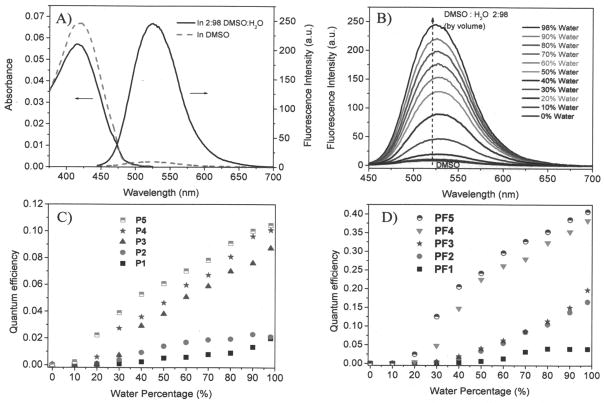
Figure 1A showed the typical absorbance and emission spectra of PF4 in DMSO and in DMSO/H2O (2:98 by volume). The polymer in DMSO had almost no emission with quantum yield of 0.02%. At the same polymer concentration, with the increase of water fraction in DMSO, the absorbance decreases and the fluorescence intensity increases (Figure 1B). These phenomena were observed in other AIE materials,11,14 suggesting the typical AIE characteristics. The quantum yield of PF4 in DMSO/H2O (2:98 by volume) increased to 38%, which is 1900 times greater than in pure DMSO. Figure 1C and 1D showed the typical quantum yields of the polymers P1–P5 and PF1–PF5 at the DMSO/H2O mixtures, indicating material dependent photophysical properties, which were summarized in Table 1.
Figure 1.
A) The absorbance and emission spectra of a typical polymer PF4 in DMSO and 2% DMSO aqueous solution (0.1 mg/mL). B) The emission intensity change of PF4 in the mixture of DMSO and water. Emission spectra were excited at 405 nm. C) Quantum yields of the series 1 polymers P1–P5 in DMSO and water mixtures. D) Quantum yields of the series 2 polymers PF1–PF5 in DMSO and water mixtures.
Table 1.
Properties of the polymers
| λ ab,
a nm
|
λ em,
b nm
|
CMC mg/mL | Diameter, e (nm) | 19F T1, h (ms) | 19F T2, h (ms) | 19F T1, i (ms) | 19F T2, i (ms) | |||
|---|---|---|---|---|---|---|---|---|---|---|
| Soln, c | Aggr, d | Soln (η) | Aggr (η) | |||||||
| P1 | 412 | 405 | 521 (0.013) | 530 (2.0) | 0.033 | ----f | ||||
| P2 | 408 | 405 | 518 (0.011) | 535 (2.1) | 0.032 | 6.9 | ||||
| P3 | 418 | 414 | 528 (0.013) | 538 (8.7) | 0.014 | 8.6 | ||||
| P4 | 420 | 415 | 530 (0.013) | 540 (10.1) | 0.011 | 8.0 | ||||
| P5 | 420 | 416 | 533 (0.010) | 540 (10.4) | 0.006 | 8.1 | ||||
| PF1 | 422 | 417 | 520 (0.010) | 531 (3.9) | 0.041 | 22 | 274 | 65 | ||
| PF2 | 419 | 415 | 520 (0.016) | 524 (16.5) | 0.034 | 26 | 237 | 28 | 215 | 33 |
| PF3 | 418 | 415 | 520 (0.012) | 525 (19.7) | 0.034 | 21 | 276 | 36 | 260 | 42 |
| PF4 | 416 | 411 | 520 (0.017) | 516 (38.3) | 0.033 | 21 | 244 | 11 | ||
| PF5 | 411 | 410 | 521 (0.003) | 518 (40.7) | 0.034 | ----g | ||||
Absorption maximum.
Emission maximum (with quantum yield (η, %) given in the parentheses); excitation wavelength: 425 nm.
Solutions (in DMSO).
Aggregates (in 2% DMSO aqueous solutions).
by DLS.
no reliable data.
not measured because of the poor solubility.
in 2% DMSO aqueous solutions with polymer concentrations of 10 mg/mL.
in 10 mM HEPES buffers (pH 7.2) with polymer concentrations of 10 mg/mL.
All the polymer segments, PHPMA, PMATMA, PAIE, and/or PTFEMA have very good solubility in DMSO. The AIE fluorophores can rotate freely in DMSO to lose their energies resulting in their extremely weak emission intensities. With the addition of water into the polymer solutions in DMSO, the hydrophobic AIE fluorophores started to self-assemble with the hydrophilic PHPMA and PMATMA polymer chains, possibly through the formation of micellar nanostructures. The hydrophobic PAIE segments aggregate together as the hydrophobic cores, limiting or restricting the intramolecular rotations of the AIE fluorophores to increase the fluorescence intensities. With more water fractions, the aggregations became more compact. This is the typical characteristic of AIE phenomenon. Investigations revealed that the AIE phenomenon was caused by the restricted intramolecular motions of the luminogens in their aggregate states, which blocked the nonradiative decay channels and thus enhanced fluorescence intensities.10c,d As shown in Figure 1C, for the polymers with more hydrophobic PAIE segments, the aggregations of the PAIE segments started earlier with lower water fractions. At the same DMSO/H2O fraction, the polymers with higher AIE fractions exhibited higher quantum yields. When the AIE fluorophore’s fraction reached a certain level, for example over the molar fraction of P4, the quantum yield change was not significant with the further increase of AIE fractions. For P5, the percentage of PAIE reached 16-mol% of PHPMA, only 10% quantum yield was achieved. For the fluorine-containing polymers, although only a small percentage of PAIE (1-mol% of PHPMA) was used, high quantum yields of about 40% could be achieved using PF4 and PF5 (Figure 1D). This was attributed to that PTFEMA provided hydrophobic environment for AIE fluorophore to facilitate its aggregations. Therefore, we have demonstrated that the aggregations of AIE fluorophores could be manipulated and high quantum yields could be achieved using only a small percentage of AIE fluorophores by integrating PTFEMA-containing segments.
Photostability of the fluorophores were studied. The polymers in pH 7.4 HEPES buffers were exposed continuously under 405 nm laser (0.2 mW/cm2) for 2 hours. A decrease of about 5.1% of fluorescence intensity was observed. This may be due to the photobleaching of the fluorophores by light, which is a common problem of many organic fluorophores. The fluorescence intensity decrease of the AIE fluorophores was higher than that of fluorescein (~ 3.1%). Designing new AIE fluorophores to improve the photostability is necessary.
3.3. Nanostructures
In order to determine whether these polymers can form nanostructures, the polymer solutions were measured using dynamic light scattering (DLS). Small particles with diameters of around 7 to 9 nm for P2–P5 and around 21 to 25 nm for PF1–PF5 in DMSO/H2O (2:98 by volume) were observed (Table 1 and Figure 2A), suggesting the polymers’ aggregated nanostructures. Confirmation of the micellar nanostructures was visualized under AFM, using PF4 as an example. Small spherical micelles (Figure 2B) with an average diameter of 36 ± 10 nm were observed, which is larger than that measured by DLS (22 nm). This difference is probably attributed to the flattening of the micelles on the mica surface during the drying process.
Figure 2.
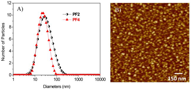
A) Typical DLS of PF2 and PF4 in 2% DMSO aqueous solutions. B) AFM image of PF2 (1.5 μm × 1.5 μm).
Some random copolymers with both the hydrophilic and hydrophobic units were reported to form micelles with the hydrophobic segments as the micellar cores and hydrophobic chains as the shells.28 Critical micellar concentration (CMC) is an important factor for determination of micelle formation. For the fluorescent polymers, CMCs can be determined by the measurement of the concentration dependent fluorescence in aqueous solutions.26b When the polymer concentration is extremely low, the polymers are in the forms of unimers in the solutions. At this condition, the polymers did not self-assemble to form micelles. Therefore, there are no obvious aggregations of the AIE fluorophores and very week fluorescence was observed. When the polymer concentrations are over their CMCs, the polymers will form micelles to enable the aggregations of the hydrophobic AIE segments in the micellar cores. This will result in the observation of strong fluorescence. Meanwhile, the fluorescence intensities after CMC increased with the increases of concentrations. Fluorescence intensities were plotted against the polymer concentrations in double distilled water (Supporting S-Figure 1 and 2). It was found the CMCs of P1 to P5 are from 0.033 mg/mL to 0.006 mg/mL (Table 1), decreasing with the increase of AIE fractions. This result showed that hydrophobic AIE segments played a significant role for the self assembly of the series 1 polymers. However, CMCs of series 2 polymers did not depend on hydrophobic segments fractions and the CMCs of series 2 polymers are close to that of P1; however they are higher than others of series 1. Most likely, the long segment of AIE fluorophore played a key role for reducing the CMC, not the short trifluoroethyl segments.
It has been known that the CMC values depend on polymer structures, molecular weights, and the fractions of hydrophobic segments to hydrophilic segments. Some random copolymers were reported to have high CMCs of 2.0 mg/mL.28b Some other random copolymers were reported to have much lower CMCs of around 5.3 × 10⁻⁴ mg/mL.28c Our polymers’ CMCs fell within the reported ranges.
3.4. 19F NMR, T1, and T2
The micelles derived from polymers PF1–PF3 exhibited a single, narrow resonance by 19F NMR spectra, with a half-width of approximately 100 Hz (Figure 3A). The micelle of PF4 exhibited a broad and weak 19F resonance peak. When there are more fluorine-containing hydrophobic segments in the micellar cores, the motions of fluorine atoms are more limited, resulting in the broadening effects of 19F signals and decreasing of its intensity. For the same polymer, the increase of concentration results in an increase of its 19F signals (Figure 3B). For PF3, its detection limit by 19F NMR at our experiment condition is 1 mg/mL, corresponding to 19F at a molar concentration of 4.33 mM.
Figure 3.
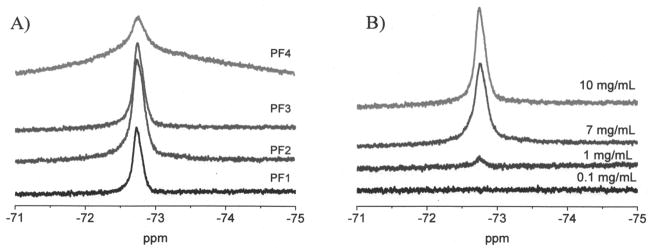
A) 19F NMR spectra of PF1 to PF4 in H2O and DMSO (98:2 by volume) at 10 mg/mL. Chemical shift is referenced to CF3COOH. B) 19F NMR spectra of PF3 at different concentration in the 2% of DMSO aqueous solutions.
T1 and T2 of the polymers were investigated in both 2% DMSO aqueous solutions and 10 mM HEPES buffers (pH 7.2) at a polymer concentration of 10 mg/mL. Data were summarized in Table 1. T1 values of these polymers are in a small variation in percentages from 237 to 276 ms. T2 values are in a large variation percentages from 11 to 65 ms. Solvents of 2% DMSO aqueous solution and 10 mM HEPES buffer affected the T1 and T2 values slightly. Nurmi et al.21b reported that T2 was more sensitive to environments and fluorine contents in the statistical copolymers. Our results showed that the fluorine moieties not only affected the quantum yields of the AIE fluorophores in the polymers but also affected the T1 and T2 values of the amphiphilic polymers.
3.5. Fluorescence bioimaging
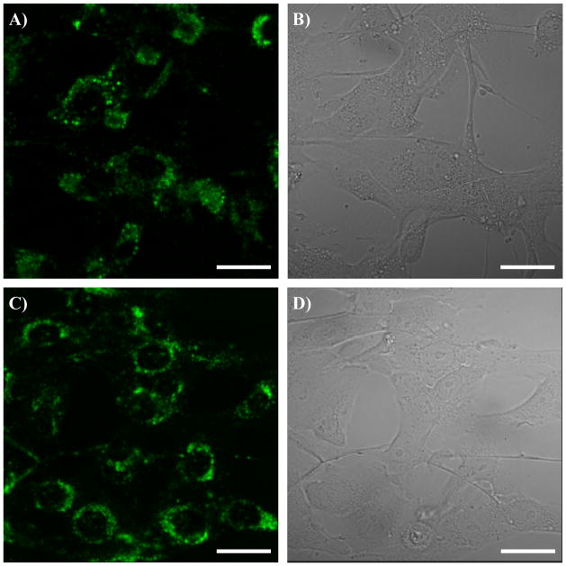
All the polymers were taken up by two cell lines (U87MG and CP-A). Figure 4 showed the confocal fluorescence microscopy images of one typical polymer, PF3, for two cell lines (U87MG and CP-A) after 24 hours of internalization with cells at 37°C. Green emission was observed, which was randomly distributed in the cytoplasma area of the cells, showing the polymer was successfully taken up by the cells. The cellular uptakes of the polymers were further confirmed by fluorescence measurements using flow cytometry (Supporting S-Figure 3).
Figure 4.
Confocal fluorescence images of PF3 for U87MG (A and B) and CP-A (C and D). A and C are fluorescence images. B and D are bright field images. Scale bar is 10 μm.
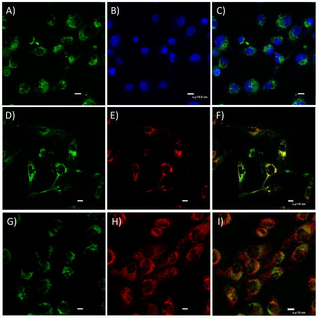
PF3 was used as a typical polymer for more detailed investigation of the subcellular colocalizations. Figure 5 showed the subcellular distributions of the polymer in live CP-A cells. The green emissions from the polymer have only minimal co-localizations with blue emissions from nuclei stained by Hoechst 33342 (A, B, and C), further confirming its distribution in cytoplasm region. Significant overlays of the green emissions with the red emissions of LysoTracker Red® (D, E, and F) and of MitoTracker Red® (G, H and I) were observed. The yellow colors in F and I indicated the same subcellular localizations of the LysoTracker Red® or MitoTracker Red® with PF3, respectively. The corresponding Pearson’s sample correlation factors 29 were calculated to be 69% for the co-localizations with lysosomes and 55% for the co-localizations with mitochondria, respectively. These results showed that the polymer was randomly distributed in the cytoplasm and did not have specific localizations in the organelles like lysosomes and mitochondria.
Figure 5.
Confocal fluorescence images of PF3 in CP-A cells co-stained with nuclei staining Hoechst 33342 (A, B, and C), LysoTracker Red® (D, E, and F), and MitoTracker® (G, H, I), respectively. A, D, and G represent the green channels from the AIE fluorophores. B is from the blue channel of the nuclei staining agent of Hoechst 33342. E is from the red channel of the lysosome specific LyosTracker Red®. H is from the red channel of the mitochondria specific MitoTracker Red®. C is the overlay of A and B. F is the overlay of D and E. I is the overlay of G and H. The scale bar represents 10 μm. For better resolution, C, F, and I were magnified and given in supplementary figures of S-Figure 4, 5, and 6.
3.6. Time and temperature dependent flow cytometry
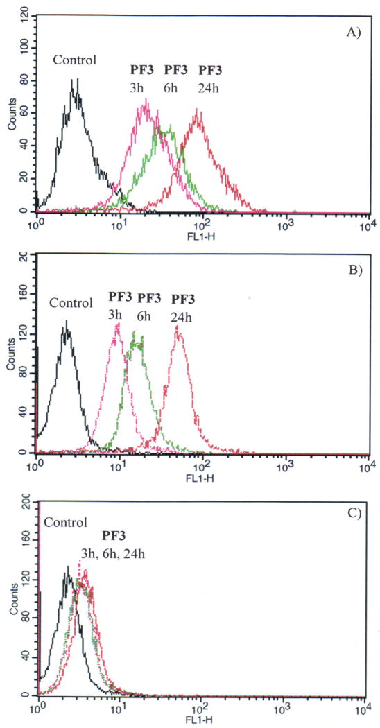
In order to understand the possible cellular uptake mechanism, flow cytometry was used to measure the fluorescence of the cells after internalization with the polymers. PF3 was used as a typical polymer. Figure 6A and 6B gave the time dependent fluorescence of the polymer internalized with cells at 37 °C. The fluorescence, which was due to the cellular uptake of the polymer, became stronger under longer cellular internalization time. This result suggests the cellular uptake of the polymer is time dependent. Figure 6C gave the time dependent fluorescence of the polymer internalized with cells at 4 °C by CP-A cells. Comparing Figure 6B with Figure 6C, it can be found under the same cellular internalization time, more polymers were taken up by cells at a higher temperature (37 °C) than at a lower temperature (4 °C). These results showed that the cellular internalization of the polymer is energy dependent. This characteristic suggests the endocytosis mechanism of the cellular internalization with polymers, which is time and energy dependent.30
Figure 6.
A) Time dependent flow cytometry of PF3 by U87MG cells at 37 °C. B) Time dependent flow cytometry of PF3 by CP-A cells at 37 °C. C) Time dependent flow cytometry of PF3 by CP-A cells at 4 °C.
3.7. Cytotoxicity evaluation using MTT assay
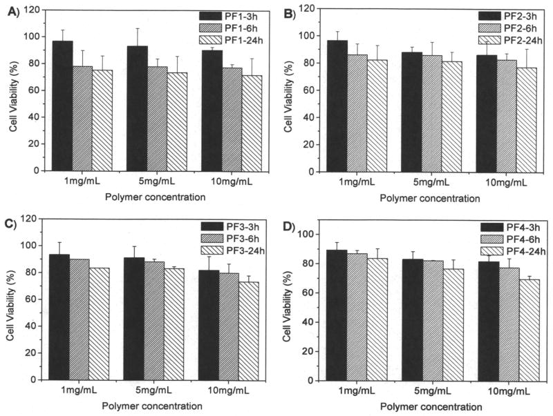
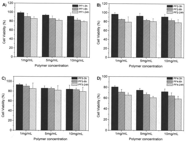
MTT assay is based on the intracellular reduction of a tetrazolium (MTT) dye to a formazan product measured spectrophotometrically and is used for high-throughput screening.31 Figure 7 showed the typical cell viability of two polymers of P1 and P4 for U87MG and CP-A cells after 24 hours internalization. For P1, concentration and time dependent cytotoxicity was observed. While for the other polymers, no significant cytotoxicity was observed using a polymer concentration of 1 mg/mL after cellular internalization of 24 hours. It has been reported that polymers with positive charges may be toxic to cells. P1 probably has the highest charge density, resulting in its significant cytotoxicity to cells. Our results suggested that controlling charge density is an important factor for reducing materials toxicity. For the polymers PF1 and PF4, we studied the cytotoxicity to cells at high concentrations up to 10 mg/mL (Figures 8 and 9). Results showed that all the four polymers have slight toxicity at a polymer concentration of 10 mg/mL after 24 hours cellular internalizations. Cell viability was > 70% compared to untreated control. This observation suggests these polymers may have potentials for in vivo applications.
Figure 7.
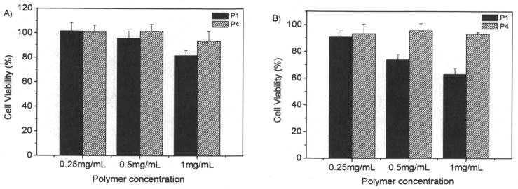
Cytotoxicity of P1 and P4 to U87MG (A) and CP-A (B) cells. Cellular internalization time is 24 hours.
Figure 8.
Cytotoxicity of PF1 to PF4 to U87MG cells. Cellular internalization time is from 3 hours to 24 hours.
Figure 9.
Cytotoxicity of PF1 to PF4 to CP-A cells. Cellular internalization time is from 3 hours to 24 hours.
4. Conclusions
Two new series of PHPMA based random copolymers with hydrophobic AIE fluorophores were prepared. The increase of the molar fractions of the hydrophobic AIE fluorophores and/or the trifluoroethyl moieties results in the higher quantum yields of the AIE fluorophores in aqueous solutions. Using 1-mol% of AIE fluorophore with the tuning of the molar fraction of TFEMA, 40% quantum yield was achieved. Compared to the polymers without the TFEMA segments, less than 10% quantum yield was obtained. This is the first time to integrate the AIE fluorophores with fluorinated polymers to manipulate the quantum yields of the AIE fluorophores. Because of the introduction of the hydrophobic AIE fluorophores and/or TFEMA segments in the polymers, the polymers can self-assemble to form small micelles. All the polymers are cell permeable and located in the cellular cytoplasma area. Cellular uptake was demonstrated to be through endocytosis mechanism, which is time and energy dependent. Although the AIE fluorophore and TFEMA segments are water insoluble, their chemical conjugation with biocompatible polymers such as the PHPMA enables its application in biological conditions. The polymers also showed reasonable T1 and T2 values. Thus besides the fluorescent bioimaging, we expect that the polymers are applicable for 19F MRI.
Supplementary Material
Acknowledgments
This work was supported by NIH National Human Genome Research Institute, Centers of Excellence in Genomic Science, Grant Number 5 P50 HG002360 (Dr. Deirdre Meldrum, PI, Director). Dr. Brian J. Reid and Dr. Tom Paulson at Fred Hutchison Cancer Research Center (Seattle, WA) were acknowledged for kindly providing us the CP-A cell line. Hongguang Lu thanks the China Scholarship Council scholarship program for overseas graduate students.
References
- 1.a) Burroughes JH, Bradley DDC, Brown AR, Marks RN, Mackay K, Friend RH, Burns PL, Holmes AB. Nature. 1990;347:539. [Google Scholar]; b) Forrest SR. Nature. 2004;428:911. doi: 10.1038/nature02498. [DOI] [PubMed] [Google Scholar]
- 2.a) McQuade DT, Pullen AE, Swager TM. Chem Rev. 2000;100:2537. doi: 10.1021/cr9801014. [DOI] [PubMed] [Google Scholar]; b) Tian Y, Chen CY, Yang CC, Young AC, Jang SH, Chen WC, Jen AKY. Chem Mater. 2008;20:1977. [Google Scholar]
- 3.a) Bruchez MJ, Moronne M, Gin P, Weiss S, Alivisatos AP. Science. 1998;281:2013. doi: 10.1126/science.281.5385.2013. [DOI] [PubMed] [Google Scholar]; b) Misgeld T, Kerschensteiner M, Bareyre FM, Burgess RW, Lichtman JW. Nat Methods. 2007;4:559. doi: 10.1038/nmeth1055. [DOI] [PubMed] [Google Scholar]
- 4.Johnson ID, Spence MTZ. The Molecular Probes® Handbook: A Guide to Fluorescent Probes and Labeling Technologies. 11. Carlsbad, CA, USA: 2010. [Google Scholar]
- 5.Bouteiller C, Clave G, Bernardin A, Chipon B, Massonneau M, Renard P, Romieu A. Bioconjugate Chem. 2007;18:1303. doi: 10.1021/bc0700281. [DOI] [PubMed] [Google Scholar]
- 6.Xiong LQ, Chen ZG, Yu MX, Li FY, Liu C, Huang CH. Biomaterials. 2009;30:5592. doi: 10.1016/j.biomaterials.2009.06.015. [DOI] [PubMed] [Google Scholar]
- 7.a) Woo HY, Korystov D, Mikhailovsky A, Nguyen T, Bazan GC. J Am Chem Soc. 2005;127:13794. doi: 10.1021/ja054911q. [DOI] [PubMed] [Google Scholar]; b) Tian YQ, Chen CY, Young AC, Tucker NM, Jen AKY. Adv Funct Mater. 2007;17:1691. [Google Scholar]; c) Law W, Yong K, Roy I, Xu GX, Ding H, Bergey EJ, Zeng H, Prasad PN. J Phys Chem C. 2008;112:7972. [Google Scholar]; d) Tian YQ, Wu WC, Chen CY, Jang SH, Zhang M, Strovas T, Anderson J, Cookson B, Li Y, Meldrum D, Chen WC, Jen AKY. J Biomed Mater Res A. 2010;93:1068. doi: 10.1002/jbm.a.32607. [DOI] [PMC free article] [PubMed] [Google Scholar]
- 8.a) Kraft A, Grimsdale AC, Holmes AB. Angew Chem Int Ed. 1998;37:402. doi: 10.1002/(SICI)1521-3773(19980302)37:4<402::AID-ANIE402>3.0.CO;2-9. [DOI] [PubMed] [Google Scholar]; b) Grimsdale AC, Chan KL, Martin RE, Jokisz PG, Holmes AB. Chem Rev. 2009;109:897. doi: 10.1021/cr000013v. [DOI] [PubMed] [Google Scholar]
- 9.Luo J, Xie Z, Lam JWY, Cheng L, Chen H, Qiu C, Kwok HS, Zhan X, Liu Y, Zhu D, Tang BZ. Chem Commun. 2001:1740. doi: 10.1039/b105159h. [DOI] [PubMed] [Google Scholar]
- 10.a) Lim SJ, An BK, Jung SD, Chun MA, Park SY. Angew Chem Int Ed. 2004;43:6346. doi: 10.1002/anie.200461172. [DOI] [PubMed] [Google Scholar]; b) Kim S, Zheng Q, He GS, Bharali DJ, Pudavar HE, Baev A, Prasad PN. Adv Funct Mater. 2006;16:2317. [Google Scholar]; c) He JT, Xu B, Cheng FP, Xia HJ, Li K, Ye L, Tian WJ. J Phys Chem C. 2009;113:9892. [Google Scholar]; d) Qin A, Lam JWY, Tang BZ. Prog Polym Sci. 2012;37:182. [Google Scholar]
- 11.Hong Y, Häußler M, Lam JWY, Li Z, Sin KK, Dong Y, Tong H, Liu J, Qin A, Renneberg R, Tang BZ. Chem Eur J. 2008;14:6428. doi: 10.1002/chem.200701723. [DOI] [PubMed] [Google Scholar]
- 12.Wang M, Zhang DQ, Zhang GX, Zhu DB. Chem Commun. 2008:4469. doi: 10.1039/b808877b. [DOI] [PubMed] [Google Scholar]
- 13.Zhao MC, Wang M, Liu HJ, Liu DS, Zhang GX, Zhang DQ, Zhu DB. Langmuir. 2009;25:676. doi: 10.1021/la803762b. [DOI] [PubMed] [Google Scholar]
- 14.Lu H, Xu B, Dong Y, Chen F, Li Y, Li Z, He J, Li H, Tian WJ. Langmuir. 2010;26:6838. doi: 10.1021/la904727t. [DOI] [PubMed] [Google Scholar]
- 15.Liu Y, Tang Y, Barashkov NN, Irgibaeva IS, Lam JWY, Hu R, Birimzhanova D, Yu Y, Tang BZ. J Am Chem Soc. 2010;132:13951. doi: 10.1021/ja103947j. [DOI] [PubMed] [Google Scholar]
- 16.Liu Y, Deng C, Tang L, Qin A, Hu R, Sun JZ, Tang BZ. J Am Chem Soc. 2011;133:660. doi: 10.1021/ja107086y. [DOI] [PubMed] [Google Scholar]
- 17.a) Kim S, Pudavar HE, Bonoiu A, Prasad PN. Adv Mater. 2007;19:3791. [Google Scholar]; b) Kim S, Ohulchanskyy TY, Pudavar HE, Pandey RK, Prasad PN. J Am Chem Soc. 2007;129:2669. doi: 10.1021/ja0680257. [DOI] [PMC free article] [PubMed] [Google Scholar]; c) Liu J, Lam JWY, Tang BZ. J Inorg Organomet Polym. 2009;19:249. [Google Scholar]; d) Lim CK, Kim S, Kwon IC, Ahn CH, Park SY. Chem Mater. 2009;21:5819. [Google Scholar]; e) Wu WC, Chen CY, Tian YQ, Jang SH, Hong YN, Liu Y, Hu R, Tang BZ, Chen CT, Chen WC, Jen AKY. Adv Funct Mater. 2010;20:1413. [Google Scholar]
- 18.Valeur B. Molecular Fluorescence: Principle and Applications. Chapter 7. Wiley-VCH; Weinheim, Germany: 2002. [Google Scholar]
- 19.Lu H, Su F, Mei Q, Zhou X, Tian Y, Tian W, Johnson RH, Meldrum DR. J Polym Sci Part A: Polym Chem. 2012;50:890. doi: 10.1002/pola.25841. [DOI] [PMC free article] [PubMed] [Google Scholar]
- 20.Srinivas M, Heerschap A, Ahrens ET, Figdor CG, de Vries IJ. Trends Biotechnol. 2010;28:363. doi: 10.1016/j.tibtech.2010.04.002. [DOI] [PMC free article] [PubMed] [Google Scholar]
- 21.a) Janjic JM, Ahrens ET. Wiley Interdiscip Rev Nanomed Nanobiotechnol. 2009;1:492. doi: 10.1002/wnan.35. [DOI] [PMC free article] [PubMed] [Google Scholar]; b) Nurmi L, Peng H, Seppälä J, Haddleton DM, Blakeyb I, Whittaker AK. Polym Chem. 2010;1:1039. [Google Scholar]; c) Ruiz-Cabello J, Barnett BP, Bottomley PA, Bulte JWM. NMR Biomed. 2011;24:114. doi: 10.1002/nbm.1570. [DOI] [PMC free article] [PubMed] [Google Scholar]
- 22.Du W, Nyström AM, Zhang L, Powell KT, Li Y, Cheng C, Wickline SA, Wooley KL. Biomacromolecules. 2008;9:2826. doi: 10.1021/bm800595b. [DOI] [PMC free article] [PubMed] [Google Scholar]
- 23.Ogawa M, Nitahara S, Aoki H, Ito S, Narazaki M, Matsuda T. Macromol Chem Phys. 2010;211:1602. [Google Scholar]
- 24.Thurecht KJ, Blakey I, Peng H, Squires O, Hsu S, Alexander C, Whittaker AK. J Am Chem Soc. 2010;132:5336. doi: 10.1021/ja100252y. [DOI] [PubMed] [Google Scholar]
- 25.a) Lu ZR, Ye F, Vaidya A. J Control Release. 2007;122:269. doi: 10.1016/j.jconrel.2007.06.016. [DOI] [PMC free article] [PubMed] [Google Scholar]; b) Cuchelkar V, Kopečková P, Kopeek J. Macromol Biosci. 2008;8:375. doi: 10.1002/mabi.200700240. [DOI] [PubMed] [Google Scholar]
- 26.(a) Song HT, Choi JS, Huh YM, Kim S, Jun YW, Suh JS, Cheon J. J Am Chem Soc. 2005;127:9992. doi: 10.1021/ja051833y. [DOI] [PubMed] [Google Scholar]; b) Tian YQ, Wu WC, Chen CY, Strovas T, Li YZ, Jin YG, Su F, Meldrum DR, Jen AKY. J Mater Chem. 2010;20:1728. doi: 10.1039/b922435c. [DOI] [PMC free article] [PubMed] [Google Scholar]
- 27.Joshi HS, Jamshidi R, Tor Y. Angew Chem Int Ed. 1999;38:2721. doi: 10.1002/(sici)1521-3773(19990917)38:18<2721::aid-anie2721>3.0.co;2-5. [DOI] [PubMed] [Google Scholar]
- 28.a) Barz M, Luxenhofer R, Zentel R, Kabanov AV. Biomaterials. 2009;30:5682. doi: 10.1016/j.biomaterials.2009.06.058. [DOI] [PMC free article] [PubMed] [Google Scholar]; b) Tominaga Y, Mizuse M, Hashidzume A, Morishima Y, Sato T. J Phys Chem B. 2010;114:11403. doi: 10.1021/jp104711q. [DOI] [PubMed] [Google Scholar]; c) Yin C, Li X, Wu Q, Wang JL, Lin XF. J Colloid Interface Sci. 2010;349:153. doi: 10.1016/j.jcis.2010.05.028. [DOI] [PubMed] [Google Scholar]
- 29.a) Tian YQ, Su F, Weber W, Nandakumar V, Shumway BR, Jin Y, Zhou X, Holl M, Johnson RH, Meldrum DR. Biomaterials. 2010;31:7411. doi: 10.1016/j.biomaterials.2010.06.023. [DOI] [PMC free article] [PubMed] [Google Scholar]; b) Manders EMM, Verbeek FJ, Aten JA. J Microscopy. 1993;169:375. doi: 10.1111/j.1365-2818.1993.tb03313.x. [DOI] [PubMed] [Google Scholar]; c) Zinchuk V, Zinchuk O, Okada T. Acta Histochemica et Cytochemica. 2007;40:101. doi: 10.1267/ahc.07002. [DOI] [PMC free article] [PubMed] [Google Scholar]
- 30.a) Gonda K, Komatsu M, Numata O. Cell Struct Funct. 2000;25:243. doi: 10.1247/csf.25.243. [DOI] [PubMed] [Google Scholar]; b) Sankaranarayanan S, Ryan TA. Nat Neurosci. 2001;4:129. doi: 10.1038/83949. [DOI] [PubMed] [Google Scholar]; c) Beutner D, Voets T, Neher E, Moser T. Neuron. 2001;29:681. doi: 10.1016/s0896-6273(01)00243-4. [DOI] [PubMed] [Google Scholar]; d) Yuan A, Siu CH, Chia CP. Cell Calcium. 2001;29:229. doi: 10.1054/ceca.2000.0184. [DOI] [PubMed] [Google Scholar]; e) Luo L, Tam J, Maysinger D, Eisenberg A. Bioconjugate Chem. 2002;13:1259. doi: 10.1021/bc025524y. [DOI] [PubMed] [Google Scholar]
- 31.a) Carmichael J, Degraff WG, Gazdar AF, Minna JD, Michell JB. Cancer Res. 1987;47:936. [PubMed] [Google Scholar]; b) Mosmann T. J Immunol Methods. 1983;65:55. doi: 10.1016/0022-1759(83)90303-4. [DOI] [PubMed] [Google Scholar]
Associated Data
This section collects any data citations, data availability statements, or supplementary materials included in this article.


