Abstract
Quadrupeds have versatile gait patterns, depending on the locomotion speed, environmental conditions and animal species. These locomotor patterns are generated via the coordination between limbs and are partly controlled by an intraspinal neural network called the central pattern generator (CPG). Although this forms the basis for current control paradigms of interlimb coordination, the mechanism responsible for interlimb coordination remains elusive. By using a minimalistic approach, we have developed a simple-structured quadruped robot, with the help of which we propose an unconventional CPG model that consists of four decoupled oscillators with only local force feedback in each leg. Our robot exhibits good adaptability to changes in weight distribution and walking speed simply by responding to local feedback, and it can mimic the walking patterns of actual quadrupeds. Our proposed CPG-based control method suggests that physical interaction between legs during movements is essential for interlimb coordination in quadruped walking.
Keywords: quadruped locomotion, interlimb coordination, central pattern generator, physical interaction
1. Introduction
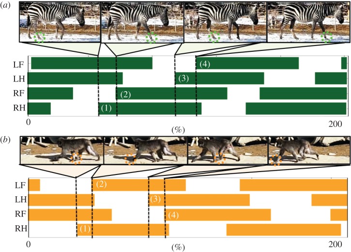
Quadrupeds exhibit versatile gait patterns (walk, trot, pace, bound, etc.), in response to the locomotion speed and environmental conditions [1,2]. Furthermore, in low-speed locomotion, different walking patterns are observed in different quadruped animals; horses exhibit a so-called lateral-sequence walk (L-S walk; figure 1a), in which the feet touch down in the order right hind (RH), right fore (RF), left hind (LH) and left fore (LF), whereas primates exhibit a so-called diagonal-sequence walk (D-S walk; figure 1b), in which the feet touch down in the order RH, LF, LH and RF [3–6]. Human beings are no exception in that the crawling gait of infants gradually changes from an L-S walk to a D-S walk in the ontogeny [4,7]. These locomotor patterns are generated via the coordination of limb movements, i.e. interlimb coordination. However, the interlimb coordination mechanism responsible for the generation of such locomotor patterns is largely unknown. Thus, further clarification of this mechanism is required in order to design an adaptable and multi-functional quadruped robot as well as to understand the fundamental mechanism responsible for the remarkable abilities of quadrupeds.
Figure 1.
Gait diagram in quadruped locomotion obtained from behavioural observations of animals. Highlighted regions represent the stance phase. (a) A zebra's lateral-sequence (L-S) walk (see electronic supplementary material, movie S1), in which the feet touch down in the order right hind (RH), right fore (RF), left hind (LH) and left fore (LF). (b) A Japanese monkey's diagonal-sequence (D-S) walk (see electronic supplementary material, movie S2), in which the feet touch down in the order RH, LF, LH and RF. These photographs are frames from videos (see electronic supplementary material, movies S1 and S2) recorded at Yagiyama Zoological Park. Captive animals housed in the zoo were videotaped using a CASIO EX-F1 at 600 frames per second as they walked on flat ground.
In order to elucidate the ability of animals to generate adaptive interlimb coordination, the locomotion generation mechanisms have been investigated by analysing neural systems. Well-known experiments that used decerebrated cats [8] have provided us with important insights into the locomotion of quadruped animals, and the results suggest that locomotion is controlled in part by an intraspinal neural network called the central pattern generator (CPG), which is capable of self-organizing coordinated movement patterns between legs [9,10]. These biological findings have prompted many researchers to investigate the self-organized locomotor patterns in quadrupeds and various types of CPG neural network models have been proposed [11–22]. This forms the basis for the current control paradigms of interlimb coordination. However, these control paradigms have limitations because they ignore the effect of the body dynamics and environment on the resulting locomotor patterns. Hence, in previous studies, interlimb neural connections have been designed on a completely ad hoc basis to obtain the desired locomotor patterns.
Our approach is different: we propose an alternative control paradigm based on a CPG model that consists of four decoupled oscillators with local sensory feedback from only a force sensor on each corresponding leg. Animal locomotion is not generated merely from neural systems, but rather from the tight interaction between neural systems, musculoskeletal systems and the real-world environment [23–26]. Thus, it is essential to elucidate the locomotion generation mechanism by analysing the interaction dynamics between these three systems as well as by analysing the neural systems themselves. Therefore, we hypothesize that interlimb coordination should rely more on physical (or non-neural) interactions during leg movements through body dynamics rather than on explicit interlimb neural connections.
Here, we present a simple-structured quadruped robot using a minimalistic approach and an unconventional CPG-based control scheme that does not require an interlimb neural connection and a predefined phase relationship but exploits the physical interaction during leg movements. Our robot exhibits good adaptability to changes in weight distribution and walking speed simply by responding to local feedback, and it can mimic the walking patterns of actual quadrupeds. The present results indicate that the weight distribution of a body plays a crucial role in the generation of quadruped walking patterns. Furthermore, the same behaviour in human and primate infants [4,7,27] strongly supports the above conclusion. Our physical interaction-based approach [28,29] is expected to pave the way for establishing a design principle for adaptable and multi-functional robots and to clarify the fundamental mechanisms responsible for the generation of adaptive locomotion in animals.
2. Quadruped robot
2.1. Design strategies
To design the quadruped robot based on the minimalistic approach, we employ three major simplifications:
— Simplification 1. The use of a phase oscillator [30] as the basic component of the CPG circuit. We designed each leg such that it is controlled by only one oscillator in our CPG model.
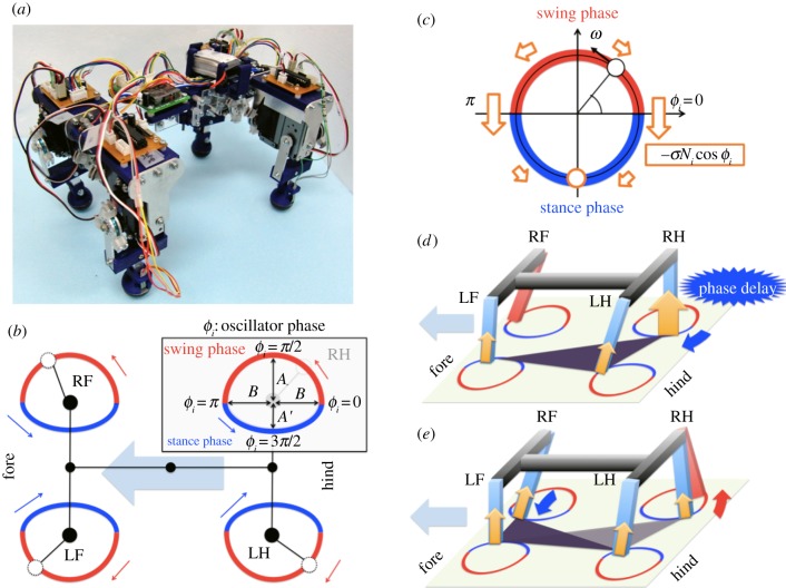
— Simplification 2. The use of a simple leg structure (no knee, no ankle), which allows us to ignore the intralimb coordination in each leg, i.e. the coordination between joint movements within each leg. As shown in figure 2b, the target position of the foot of the ith leg is actively controlled according to the corresponding oscillator phase ϕi. Further, the ith leg tends to lift off the ground (swing phase) for
 , whereas it tends to remain on the ground to support the body (stance phase) for
  (appendix B).
— Simplification 3. The interlimb neural connection between the oscillators is ignored in order to generate the interlimb coordination by exploiting only local sensory information about the force in each leg that leads to the physical interaction during leg movements.
Figure 2.
(a) Constructed robot. (b) Target trajectories. Boxed diagram illustrates target trajectory of RH leg on the basis of the oscillator phase. (c) Dynamics in the phase oscillator depending on local sensory feedback. Phase is pulled towards 3π/2 based on the local sensory feedback (indicated by the arrows). (d,e) Physical effect of the local sensory feedback. (d) Phase delay introduced by  allows another leg to enter the stance phase. (e) As the other leg begins to support the body, the feedback effect on the corresponding leg decreases, allowing it to enter the swing phase.
2.2. Mechanical structure
Figure 2a shows the entire structure of the quadruped robot, which consists of a backbone segment and four leg segments with microprocessors. The total weight of the robot is around 1.6 kg, and the lengths of the backbone and each leg are 0.28 and 0.16 m, respectively. The detailed structure of the backbone segment is shown in appendix A and illustrates the structure of one leg segment.
2.3. Control algorithm
We describe each phase oscillator that constitutes the CPG as follows:
| 2.1 |
where ω is the intrinsic angular velocity, and the second term expresses the local sensory feedback in terms of the parameter σ, which is a positive constant describing the magnitude of the feedback to the corresponding oscillator, Ni is the ground reaction force (GRF) acting on the ith leg, which is detected by the pressure sensor in each foot (appendix A).
We designed the local sensory feedback such that a leg remains in the stance phase while supporting the body (Ni > 0). With respect to equation (2.1), we note that the phase is mainly modulated to pull towards 3π/2 in the stance phase when Ni > 0 because of the influence of the local sensory feedback (figure 2c). For example, if a leg continues to bear a load (Ni > 0) at the end of its stance phase (ϕi ≈ 2π), a phase delay is introduced in response to the magnitude of Ni, as shown in figure 2d (the RH leg), which prevents the robot from entering the unstable two-legged-support state. This phase delay, which is introduced when  , allows time for another leg (e.g. the RF leg) to enter the stance phase. As the other leg begins to support the body, the load on the RH leg decreases; consequently, the feedback decreases in magnitude, allowing the RH leg to enter the swing phase (figure 2e). Therefore, the local sensory feedback, which allows the legs to maintain the stance phase by exploiting only the local force sensory information Ni from the foot, governs the appropriate relationship between the phases of the decoupled oscillators and the leg movements.
3. Experimental results
We used the quadruped robot to investigate the effects of the local sensory feedback on steady gait, adaptability to changes in body properties, the transition between standing and walking motion, and transitions during a change in the walking velocity. The control parameters and initial conditions of the phases are listed in table 1.
Table 1.
Control parameters and initial conditions.
| parameters | values | units | |
|---|---|---|---|
| ω | intrinsic angular velocity | 0.04 | rad s−1 |
| σ | magnitude of sensory feedback | 0.0052 | rad s−1 N−1 |
| A | positive y-direction amplitude of leg motion in a swing phase | 0.09 | m |
| A' | negative y-direction amplitude of leg motion in a stance phase | 0.03 | m |
| B | x-direction amplitude of leg motion | 0.04 | m |
| ϕ0(0) | initial phase on LF leg's oscillator | 0 | rad |
| ϕ1(0) | initial phase on LH leg's oscillator | 0 | rad |
| ϕ2(0) | initial phase on RF leg's oscillator | 0 | rad |
| ϕ3(0) | initial phase on RH leg's oscillator | 0 | rad |
3.1. Steady gait
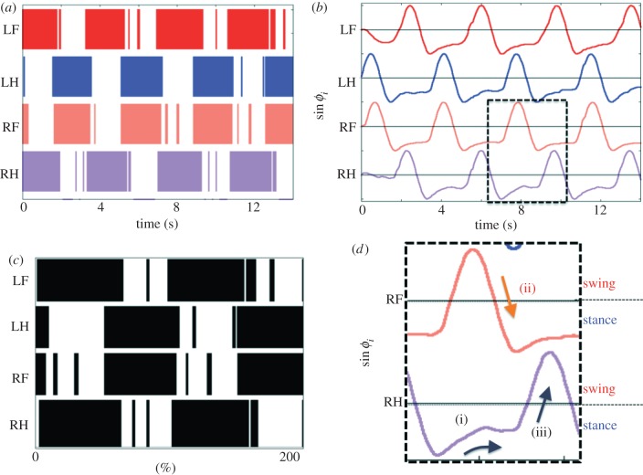
Figure 3a,b, respectively, shows the gait diagram and the phases, sin ϕi, during 0.0–14.0 s. The quadruped achieves steady walking motion by exploiting the local sensory feedback. In the gait diagram, the highlighted regions represent the stance phase, which is distinguished by using the threshold data value from the force sensor. Thin stripes in the gait diagram represent oscillations of the force sensor data around the threshold value. The data in figure 3b show that oscillator phases are mainly modified by the local sensory feedback during the stance phase (sin ϕi < 0). Although we initially set all the phases to be ϕi = 0 rad, the phase relationship immediately converges to the spatio-temporal pattern of a walking gait within approximately two periods. These results indicate that the phases of the oscillators are appropriately modified through local sensory feedback, leading to the generation of a walking gait.
Figure 3.
Experimental results of steady walking motion: (a) the gait diagram during 0.0–14.0 s, (b) corresponding phases sin ϕi, and (c) gait diagram over two cycles from 6.9 to 13.2 s in (b). (d) A magnified version of the region marked with dotted lines in (b) shows the physical effect of local force feedback. (Online version in colour.)
3.2. Adaptability to bodily changes
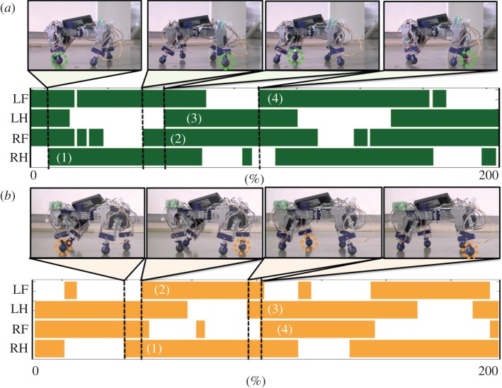
Here, we show the adaptability of our robot to changes in body properties by applying a load to the fore or hind (left and right) legs. Figure 4a,b (see electronic supplementary material, movies S3 and S4, respectively) shows the gait diagrams of the quadruped over two cycles with a load of 0.12 kg on the forelegs and a load of 0.29 kg on the hindlegs, respectively. As the figures show, the gait diagrams differ from those obtained for the case without any load (figure 3c). Table 2 lists the duty factors for the load and no load cases. The results quantitatively indicate that the duty factors of the legs bearing the load (the forelegs in figure 4a and the hindlegs in figure 4b) are larger than those of the legs bearing no load, as seen in figure 3c. Moreover, in the gait shown in figure 4a, the feet touch down in the L-S walk order. In contrast, the feet touch down in the D-S walk order in figure 4b. These results demonstrate the high adaptability of our proposed control scheme to changes in the body properties without any need to provide the data about these changes beforehand.
Figure 4.
Experimental results of the gait for changes in body properties. (a) With a load of 0.12 kg on the forelegs (see electronic supplementary material, movie S3), and (b) with a load of 0.29 kg on the hindlegs (see electronic supplementary material, movie S4). The duty factors of the legs bearing the load (the forelegs in (a) and the hindlegs in (b) are larger than those of the legs without a load.
Table 2.
Duty factors for different loading configurations.
| leg |
||||
|---|---|---|---|---|
| configurations | LF | LH | RF | RH |
| no load | 0.66 | 0.52 | 0.59 | 0.61 |
| foreleg load | 0.81 | 0.63 | 0.85 | 0.58 |
| hindleg load | 0.53 | 0.75 | 0.52 | 0.75 |
| right hindleg load | 0.51 | 0.59 | 0.59 | 0.76 |
We calculated the average duty factor, which is defined by the stance period of one foot as a percentage of the gait cycle, and diagonality, which is the percentage of the cycle period by which the left (or right) hind footfall precedes the left (or right) fore footfall, over five walking periods from three trials for each type of mass distribution: no load (figure 3c), load on the forelegs (figure 4a) and load on the hindlegs (figure 4b). The Hildebrand diagram [3–6], which is a plot of the diagonality against the duty factor obtained from our experimental results, is provided as figure 5. As the diagram quantitatively shows, the robot with a load on the forelegs exhibits an L-S walk, whereas the robot with a load on the hindlegs exhibits a D-S walk.
Figure 5.
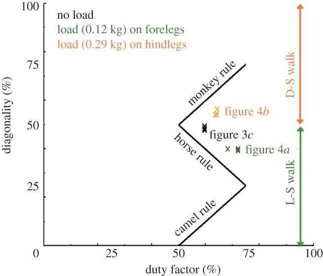
Modified Hildebrand diagram [6]: the duty factor S is plotted against diagonality D in our experimental results. The solid lines represent the equations of the revised support–polygon model (monkey rule, D = S; horse rule, D = 100−S; and camel rule: D = S−50).
3.3. Adaptability to velocity changes
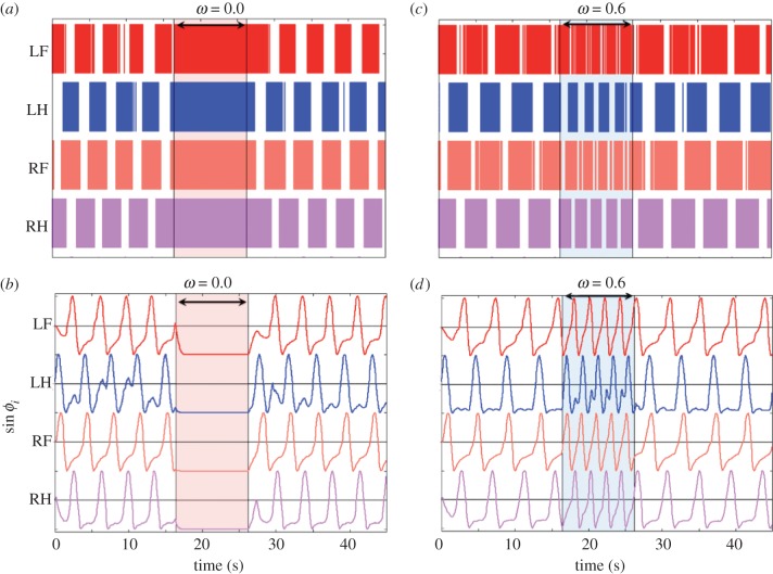
Figure 6a,b (see electronic supplementary material, movie S5) shows the experimental results of the transition between standing and walking motion by changing ω. In this experiment, we changed ω from 0.4 to 0.0 rad s−1 at t = 16.0 s and then back to 0.4 rad s−1 at t = 26.0 s (indicated by the shaded region). As the figure illustrates, the proposed control scheme allows the robot to achieve rapid transitioning between standing and walking motion by only changing the parameter ω.
Figure 6.
(a,b) Experimental results showing the transition between walking and standing motion by changing ω (see electronic supplementary material, movie S5): (a) the gait diagram and (b) the corresponding phases. The shaded region (16.0–26.0s) indicates the time during which ω = 0.0 rad s−1. (c,d) Experimental result showing the transition during a change in walking velocity by changing ω: (c) the gait diagram and (d) the corresponding phases. The shaded region indicates the time during which ω =0.6 rad s−1. (Online version in colour.)
Figure 6c,d shows the experimental results of changing ω to initiate a change in the walking velocity (ω changes from 0.4 to 0.6 rad s−1 at t =16.0 s and back to 0.4 rad s−1 at t = 26.0 s). The results indicate that our robot exhibits spontaneous transitioning during a change in the walking velocity. Moreover, we confirmed that the duty factor of each leg autonomously changes from 0.64 (ω = 0.4) to 0.56 (ω = 0.6) in response to the velocity change.
4. Mathematical interpretation
The results of the rapid convergence to steady walking (figure 3), the transition between standing and walking motion, and the transitions during a change in the walking velocity (figure 6) strongly support the claim that the proposed CPG model allows the robot to exhibit stable and smooth transitioning between each behaviour. Mathematically, the proposed model (equation (2.1)) can be rewritten in terms of the active rotator model [31] as
| 4.1 |
where  is a parameter that determines the property of the phase dynamics: oscillatory or excitatory (appendix C). It should be noted that this model has also been considered in other physical contexts [32–34].
From the dynamics of the proposed model (equation (2.1)), we obtained the potential function V(ϕi) (appendix D),
| 4.2 |
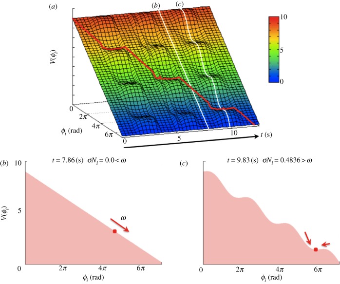
Figure 7a shows the time evolution of the potential function of our model, corresponding to the experiment of steady walking (figure 3). In this figure, the red line represents the trajectory of the phase ϕi over the potential function. Note that the local force feedback Ni modifies the shape of the potential function V(ϕi): when  , the potential function has a smooth slope, as shown in figure 7b, in which the phase changes at a constant rate ω, whereas when
  , the potential function has a varying slope, as shown in figure 7c, in which the phase converges to a local minimum and remains in that state. The time evolution of this potential function in response to the local force feedback Ni is the key to the appropriate modulation of the oscillator phases according to the situation, i.e. how each leg supports the body, leading to the generation of the adaptive interlimb coordination. The cases shown in figure 7b,c correspond to the oscillatory and excitatory regimes in the active rotator model (equation (4.1)), respectively.
Figure 7.
Dynamical structure underlying a steady walking pattern generated by the proposed control scheme. (a) Potential function V(ϕi) obtained from the dynamics of the proposed model. Ni affects the V(ϕi) curve. (b) When  in the swing phase, V(ϕi) has a smooth slope. (c) When
  in the stance phase, V(ϕi) has a varying slope, and some local minima in which the phase converges to each point and remains there. The red line in (a) represents the trajectory of the phase ϕi.
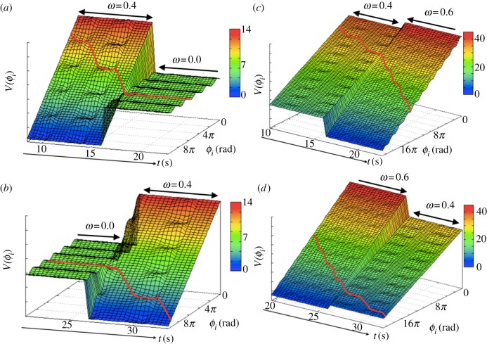
Figure 8 shows the spatio-temporal pattern of the excitatory and oscillatory regimes of our model corresponding to the experiments shown in figure 6. In the case of medium-speed walking (ω = 0.4 rad s−1), the periodic movement is represented clearly in the spatio-temporal patterns of the oscillatory and excitatory regimes (figure 7a). In contrast, in the case of standing motion (ω = 0.0 rad s−1, 16.0–26.0 s in figure 8a,b), the excitatory regime is dominant during this non-periodic movement, in which the potential function has a varying surface with respect to ϕi. In addition, in the case of high-speed walking (ω = 0.6 rad s−1, 16.0–26.0 s in figure 8c,d), the oscillatory regime is dominant during this fast periodic movement, in which the potential function has a steeper slope than ω = 0.4 rad s−1. These results indicate that the spontaneous switching between the oscillatory and excitatory regimes plays an essential role in the generation of adaptive interlimb coordination.
Figure 8.
(a,b) Spatio-temporal pattern of the excitatory and oscillatory regimes in the proposed CPG model. (c,d) Transition between walking and standing motion shown in figure 6a. Transition during a change in walking velocity shown in figure 6c.
5. Discussion
We propose an unconventional CPG model that consists of four decoupled oscillators with only local force feedback in each leg. The experimental results show that a remarkable adaptability to changes in the body properties and the control parameter ω can be successfully achieved by this model. Highly adaptive behaviour is spontaneously exhibited by the model when local sensory feedback is employed, even in the absence of direct interlimb neural connections between the oscillators of the CPG. Figure 3d shows the magnified image of the region marked with dotted lines in figure 3b, which illustrates the physical effect of the local force feedback: (i) a phase delay is introduced in the RH leg's oscillator; (ii) this phase delay, which is introduced when  allows time for another leg (the RF leg) to enter the stance phase; and (iii) as the other leg begins to support the body, the load on the RH leg decreases; consequently, the feedback effect on the RH leg decreases, allowing it to enter the swing phase. The mechanism reveals how the phases of the oscillators are appropriately modified by local sensory feedback, resulting in the generation of an adaptive walking gait.
In previous studies, various types of sensory feedback have also been proposed for adaptive locomotion generation. Taga et al. [23] proposed the concept of global entrainment between neural systems, mechanical systems and the environment, and demonstrated an adaptive bipedal walking model by achieving mutual entrainment between a CPG model and the biped's body through sensory feedback. Although this model sufficiently reproduces bipedal locomotion, it is not clear what is essential for adaptive locomotion generation because of the complexity of the neural network topology and the neural sensory feedback. Another sensory feedback technique of CPG is the phase reset scheme [18], in which the phase of the oscillator is reset to zero when the foot starts to make contact with the ground; this scheme only uses qualitative information about the foot's contact (on or off). On the other hand, our local sensory feedback uses quantitative information that describes the extent to which each foot ‘feels’ the GRF. Our results indicate that physical interlimb communication is essential for the adaptive interlimb coordination in quadruped walking.
Over the years, neurophysiologists have discussed the necessity versus sufficiency of sensory feedback in the CPG for adaptive locomotion generation. Grillner [9,10] suggested the necessity of the CPG, with others arguing the necessity of the sensory feedback [35], which plays a crucial role in adapting motor patterns in accordance with the situation encountered, e.g. locomotion speed, environmental conditions, and so on. More concretely, two sensory mechanisms have been considered important in controlling the stance-to-swing transition of a walking cat: (i) unloading of the leg and (ii) hip extension [36–38]. Furthermore, Ekeberg & Pearson [39] demonstrated that sensory information of the loading force from each leg plays a crucial role in the stance-to-swing transition by using computer simulation. On the other hand, during rapid locomotion, Full & Koditschek [40] and Ghigliazza et al. [41] have suggested that mechanical feedback plays a more essential role in the locomotion generation rather than neural sensory feedback. Our results in figure 8c,d indicate that the oscillator's regime shifts from the domain of excitatory to that of oscillatory with an increase in locomotion speed. This fact suggests that our CPG model can reproduce the autonomous transition from the domain of neural feedback (brain computation) in low-speed locomotion to that of mechanical feedback (‘morphological’ computation [25]) in middle- or high-speed locomotion by exploiting the sensory feedback on the basis of physically reasonable sensory information of loading force.
In general, quadruped gaits are described in terms of two variables: (i) the duty factor and (ii) the diagonality. When the diagonality is less than 50 per cent, each hind footfall is followed by the ipsilateral fore footfall (L-S walk), whereas when the diagonality is greater than 50 per cent, each hind footfall is followed by the diagonally opposite fore footfall (D-S walk). The results shown in figure 5 indicate that our CPG model can exhibit walking patterns similar to quadruped mammals and strongly support the idea that the mass distribution of a body plays a crucial role in the generation of quadruped walking patterns. Furthermore, the same behaviour in human and primate infants [4,7,17], i.e. the manner in which the crawling gait of infants gradually changes in the ontogeny, strongly supports the above conclusion. Although quadruped walking was well reproduced by our CPG model, differences between the actual quadruped gait (figure 1a) and our robot's gait (figure 4a) still exist; the L-S walk in figure 1a has around 10–20% diagonality (camel rule in figure 5), whereas the L-S walk in figure 4a has around 35–40% diagonality (horse rule in figure 5). This is because we designed the mechanical systems of our quadruped robot simply by employing a minimalist approach: our robot has short legs lacking knee and ankle joints. However, this fact also corresponds with biological findings [5,6], and, thus, this strongly supports the conclusion that our model can capture the basic mechanism of adaptive interlimb coordination in quadruped walking. Moreover, the discussion about the effect of leg length on gait generation is an important topic for clarifying the gait generation mechanism in quadruped animals.
6. Conclusion
Our minimalist robot can capture the basic mechanism of the interlimb coordination and mimic the gait patterns of actual quadrupeds. It is interesting to note that our model exhibits stable walking motion in accordance with the body properties without any neural communication and any predefined phase relationship between the oscillators. One plausible explanation for these results is that the proposed local sensory feedback system allows each leg to recognize the positional relationship of all the other legs, i.e. how the legs support the body at that particular moment, without having to perform computationally expensive calculations.
There is currently no systematic methodology for designing a CPG controller; each individual CPG model has been designed on a completely ad hoc basis by focusing, in particular, on the interlimb neural connections in the CPG [11–22]. To establish a design methodology, we have reworked the design principle of CPG-based control [28,29]. The proposed physical interaction-based approach may provide a useful starting point for establishing a CPG-based control design principle as well as for understanding the mechanism underlying the adaptive interlimb coordination in quadruped locomotion.
Yet, we have investigated the fundamental mechanism of interlimb coordination underlying adaptive quadruped locomotion, there are significant differences between the leg structure of our current robot and that of actual animals: actual animals' legs have many more degrees of freedom than the current robot. By exploiting the many degrees of freedom, actual quadrupeds generate adaptive locomotion through the coordination of limb movements within a leg (intralimb coordination) as well as among legs (interlimb coordination). Furthermore, actual animals' legs have a tremendous amount of sensors informing various kinds of sensor modality. Considering these facts, in the next step, we plan to focus not only on interlimb coordination but also on intralimb coordination for adaptive quadruped locomotion exploiting various types of sensory information.
Acknowledgements
The authors thank Prof. Ryo Kobayashi of Hiroshima University and Assist. Prof. Masakazu Akiyama of Hokkaido University for their suggestions, Leona Morikawa for assistance with handling and videotaping the animals, and the staff of the Yagiyama Zoological Park for the assistance provided during the recording of videos. We also thank Takahide Sato and Kazuyuki Yaegashi for their comments on improving this manuscript.
Appendix A. Detailed mechanical structure
A.1. Backbone segment
As shown in figure 9a, the device is equipped with mechanisms equivalent to torsional springs in the roll-and-yaw direction. The mechanism of the roll torsional spring consists of two parallel duralumin plates, a backbone joint and a shoulder part. The two parallel duralumin plates allow one unit of this mechanism to deform in the roll direction as a torsional spring. Moreover, these two torsional spring units are connected by the backbone joint in the yaw direction, which is equipped with elastic elements. These mechanisms allow the backbone to deform according to the terrain during the motion.
Figure 9.
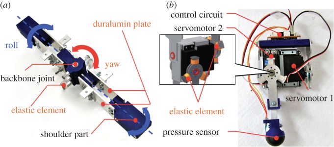
Detailed structure of the quadruped robot. (a) Backbone segment and (b) a single leg segment.
A.2. Leg segment
The simple leg structure (figure 9b) consists of the servomotors 1 and 2 (Kondo Kagaku Co. Ltd; KRS-HV Series RED Version) that drive the leg in directions parallel and perpendicular to the body axis, respectively. Each leg has a microprocessor (AVR ATmega 88P) that is used to compute the phase of the oscillator, and the two servomotors drive the leg according to the phase of the corresponding oscillator. To detect the GRFs, we equipped the feet with pressure sensors (Interlink Electronics Inc.; FSR400).
Appendix B. Leg control
As shown in figure 2b, the target position of the foot of the ith leg is actively controlled according to the corresponding phase ϕi and it is defined as follows:
| B1 |
| B2 |
and
| B3 |
where A, A' and B are positive constants such that A > A', Xi and Yi represent the sagittal and lateral components, respectively, of the position vector that defines the target position of the foot of the ith leg with reference to the corresponding shoulder or hip joint. Note that Yi is positive when the target position is away from the body. These leg movements enable the robot to alter the position of its centre of mass, allowing the legs to automatically switch between the stance and swing phases; hence, the robot achieves stable and continuous locomotion despite its simple mechanical structure.
Appendix C. Active rotator model
As shown in figure 10, the behaviour of the active rotator (equation (4.1)) can be classified into two states. When ai < ω, i.e. ω/σNi > 1, as shown in figure 10a, the active rotator exhibits oscillatory behaviour, whereby it rotates periodically around the unit circle with an angular velocity  . In contrast, when ai > ω, i.e. ω/σNi < 1, as shown in figure 10b, there exists a pair of equilibrium points at which the condition
  is satisfied: one point is stable and the other is unstable. In such a case, the active rotator exhibits excitatory behaviour, whereby it converges to a stable equilibrium point when no external force is applied, resulting in non-periodic movements. Thus, the value of ω/σNi is one index that determines the property of the phase dynamics in our proposed model.
Figure 10.
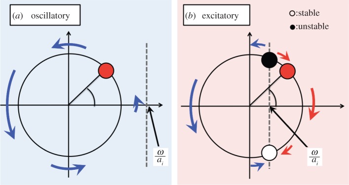
Phase dynamics of the active rotator for the cases (a) ai < ω and (b) ai > ω. The active rotator exhibits oscillatory behaviour in case (a) and excitatory behaviour in case (b). (Online version in colour.)
Appendix D. Potential function
Using a potential function V(ϕi), the dynamics of the model (equation (2.1)) is rewritten as
| D1 |
From this equation, V(ϕi) can be given by equation (4.2). Furthermore, depending on the shape of the potential function as shown in figure 7b,c, the behaviour of the model can be classified into two states: oscillatory and excitatory. As mentioned above, the local force feedback Ni determines the property of the phase dynamics by changing the shape of the potential function (figure 7a).
References
- 1.Muybridge R. 1888. Animal locomotion: the Muybridge work at the University of Pennsylvania. Ann Arbor, MI: University of Michigan Library [Google Scholar]
- 2.Hoyt DF, Taylor R. 1981. Gait and the energetics of locomotion in horses. Nature 292 239–240 10.1038/292239a0 (doi:10.1038/292239a0) [DOI] [Google Scholar]
- 3.Hildebrand M. 1965. Symmetrical gaits of horses. Science 150, 701–708 10.1126/science.150.3697.701 (doi:10.1126/science.150.3697.701) [DOI] [PubMed] [Google Scholar]
- 4.Hildebrand M. 1967. Symmetrical gaits of primates. Am. J. Phys. Anthropol. 26, 119–130 10.1002/ajpa.1330260203 (doi:10.1002/ajpa.1330260203) [DOI] [Google Scholar]
- 5.Hildebrand M. 1968. Symmetrical gaits of dogs in relation to body build. J. Morphol. 124, 353–360 10.1002/jmor.1051240308 (doi:10.1002/jmor.1051240308) [DOI] [PubMed] [Google Scholar]
- 6.Cartmill M, Lemelin P, Schmitt D. 2001. Support polygons and symmetrical gaits in mammals. Zool. J. Linn. Soc. 136 401–420 10.1046/j.1096-3642.2002.00038.x (doi:10.1046/j.1096-3642.2002.00038.x) [DOI] [Google Scholar]
- 7.Patrick SK, Noah JA, Yang JF. 2009. Interlimb coordination in human crawling reveals similarities in development and neural control with quadrupeds. J. Neurophysiol. 101, 603–613 10.1152/jn.91125.2008 (doi:10.1152/jn.91125.2008) [DOI] [PMC free article] [PubMed] [Google Scholar]
- 8.Shik ML, Severin FV, Orlovskii GN. 1966. Control of walking and running by means of electrical stimulation of the midbrain. Biophysics 11, 756–765 [PubMed] [Google Scholar]
- 9.Grillner S. 1975. Locomotion in vertebrates: central mechanisms and reflex interaction. Physiol. Rev. 55, 247–304 [DOI] [PubMed] [Google Scholar]
- 10.Grillner S. 1985. Neurobiological bases of rhythmic motor acts in vertebrates. Science 228, 143–149 10.1126/science.3975635 (doi:10.1126/science.3975635) [DOI] [PubMed] [Google Scholar]
- 11.Schöner G, Jiang WY, Kelso JAS. 1990. A synergetic theory of quadrupedal gaits and gait transitions. J. Theor. Biol. 142, 359–391 [DOI] [PubMed] [Google Scholar]
- 12.Yuasa H, Ito M. 1990. Coordination of many oscillators and generation of locomotory patterns. Biol. Cybern. 63, 177–184 10.1007/BF00195856 (doi:10.1007/BF00195856) [DOI] [Google Scholar]
- 13.Ito S, Yuasa H, Luo ZW, Ito M, Yanagihara D. 1998. A mathematical model of adaptive behaviour in quadruped locomotion. Biol. Cybern. 78, 337–347 10.1007/s004220050438 (doi:10.1007/s004220050438) [DOI] [PubMed] [Google Scholar]
- 14.Golubitsky M, Stewart I, Buono PL, Collins JJ. 1998. A modular network for legged locomotion. Physica D 115, 56–72 10.1016/S0167-2789(97)00222-4 (doi:10.1016/S0167-2789(97)00222-4) [DOI] [Google Scholar]
- 15.Golubitsky M, Stewart I, Buono PL, Collins JJ. 1999. Symmetry in locomotor central pattern generators and animal gaits. Nature 401, 693–695 10.1038/44416 (doi:10.1038/44416) [DOI] [PubMed] [Google Scholar]
- 16.Kimura H, Akiyama S, Sakurama K. 1999. Realization of dynamic walking and running of the quadruped using neural oscillator. Autonomous Robots 7, 247–258 10.1023/A:1008924521542 (doi:10.1023/A:1008924521542) [DOI] [Google Scholar]
- 17.Fukuoka Y, Kimura H, Cohen AH. 2003. Adaptive dynamic walking of a quadruped robot on irregular terrain based on biological concepts. Int. J. Robot. Res. 22, 187–202 10.1177/027836403128964926 (doi:10.1177/027836403128964926) [DOI] [Google Scholar]
- 18.Tsujita K, Tsuchiya K, Onat A. 2003. Decentralized autonomous control of a quadrupedal locomotion robot using oscillators. Artif. Life Robot. 5, 152–158 10.1007/BF02481462 (doi:10.1007/BF02481462) [DOI] [Google Scholar]
- 19.Kimura H, Fukuoka Y, Cohen AH. 2007. Biologically inspired adaptive walking of a quadruped robot. Phil. Trans. R. Soc. A 365, 153–170 10.1098/rsta.2006.1919 (doi:10.1098/rsta.2006.1919) [DOI] [PubMed] [Google Scholar]
- 20.Maufroy C, Kimura H, Takase K. 2008. Towards a general neural controller for quadrupedal locomotion. Neural Networks 21, 667–681 10.1016/j.neunet.2008.03.010 (doi:10.1016/j.neunet.2008.03.010) [DOI] [PubMed] [Google Scholar]
- 21.Righetti L, Ijspeert AJ. 2008. Pattern generators with sensory feedback for the control of quadruped locomotion. In Proc. IEEE Int. Conf. on Robotics and Automation, ICRA 2008, Pasadena, CA, 19–23 May 2008. Piscataway, NJ: IEEE. [Google Scholar]
- 22.Ijspeert AJ. 2008. Central pattern generators for locomotion control in animals and robots: a review. Neural Networks 21, 642–653 10.1016/j.neunet.2008.03.014 (doi:10.1016/j.neunet.2008.03.014) [DOI] [PubMed] [Google Scholar]
- 23.Taga G, Yamaguchi Y, Shimizu H. 1991. Self-organized control of bipedal locomotion by neural oscillators. Biol. Cybern. 65, 147–159 10.1007/BF00198086 (doi:10.1007/BF00198086) [DOI] [PubMed] [Google Scholar]
- 24.Pfeifer R, Scheier C. 1999. Understanding intelligence. Cambridge, MA: The MIT Press [Google Scholar]
- 25.Pfeifer R, Bongard J. 2006. How the body shapes the way we think: a new view of intelligence. Cambridge, MA: The MIT Press [Google Scholar]
- 26.Pfeifer R, Lungarella M, Iida F. 2007. Self-organization, embodiment, and biologically inspired robotics. Science 318, 1088–1093 10.1126/science.1145803 (doi:10.1126/science.1145803) [DOI] [PubMed] [Google Scholar]
- 27.Shapiro LJ, Raichlen DA. 2005. Lateral sequence walking in infant Papio cynocephalus: implications for the evolution of diagonal sequence walking in primates. Am. J. Phys. Anthropol. 126, 205–213 10.1002/ajpa.20049 (doi:10.1002/ajpa.20049) [DOI] [PubMed] [Google Scholar]
- 28.Umedachi T, Takeda K, Nakagaki T, Kobayashi R, Ishiguro A. 2010. Fully decentralized control of a soft-bodied robot inspired by true slime mold. Biol. Cybern. 102, 261–269 10.1007/s00422-010-0367-9 (doi:10.1007/s00422-010-0367-9) [DOI] [PubMed] [Google Scholar]
- 29.Sato T, Kano T, Ishiguro A. 2011. On the applicability of the decentralized control mechanism extracted from the true slime mold: a robotic case study with a serpentine robot. Bioinspir. Biomim. 6, 026006. 10.1088/1748-3182/6/2/026006 (doi:10.1088/1748-3182/6/2/026006) [DOI] [PubMed] [Google Scholar]
- 30.Kuramoto Y. 1984. Chemical oscillators, waves, and turbulence. New York, NY: Springer [Google Scholar]
- 31.Shinomoto S, Kuramoto Y. 1986. Cooperative phenomena in two-dimensional active rotator systems. Progr. Theoret. Phys. 75, 1319–1327 10.1143/PTP.75.1319 (doi:10.1143/PTP.75.1319) [DOI] [Google Scholar]
- 32.Stratonovich RL. 1967. Topics in the theory of random noise, New York, NY: Gordon and Breach [Google Scholar]
- 33.Ambegaokar V, Halperin BI. 1969. Voltage due to thermal noise in the dc Josephson effect. Phys. Rev. Lett. 22, 1364–1366 10.1103/PhysRevLett.22.1364 (doi:10.1103/PhysRevLett.22.1364) [DOI] [Google Scholar]
- 34.Grüner G, Zawadowski A, Chaikin PM. 1981. Nonlinear conductivity and noise due to charge-density-wave depinning in NbSe3. Phys. Rev. Lett. 46, 511–515 [Google Scholar]
- 35.Duysens J, Pearson KG. 1976. The role of cutaneous afferents from the distal hindlimb in the regulation of the step cycle of thalamic cats. Exp. Brain Res. 24, 245–255 10.1007/BF00235013 (doi:10.1007/BF00235013) [DOI] [PubMed] [Google Scholar]
- 36.Grillner S, Rossignol S. 1978. On the initiation of the swing phase of locomotion in chronic spinal cats. Brain Res. 146, 269–277 10.1016/0006-8993(78)90973-3 (doi:10.1016/0006-8993(78)90973-3) [DOI] [PubMed] [Google Scholar]
- 37.Duysens JD, Pearson KG. 1980. Inhibition of flexor burst generation by loading ankle extensor muscles in walking cats. Brain Res. 187, 321–332 10.1016/0006-8993(80)90206-1 (doi:10.1016/0006-8993(80)90206-1) [DOI] [PubMed] [Google Scholar]
- 38.Pearson KG. 2003. Generating the walking gait: role of sensory feedback. Prog. Brain Res. 143, 123–132 10.1016/S0079-6123(03)43012-4 (doi:10.1016/S0079-6123(03)43012-4) [DOI] [PubMed] [Google Scholar]
- 39.Ekeberg O, Pearson KG. 2005. Computer simulation of stepping in the hind legs of the cat: an examination of mechanisms regulating the stance-to-swing transition. J. Neurophysiol. 94, 4256–4268 10.1152/jn.00065.2005 (doi:10.1152/jn.00065.2005) [DOI] [PubMed] [Google Scholar]
- 40.Full RJ, Koditschek DE. 1999. Templates and anchors: neuromechanical hypothesis of legged locomotion on land. J. Exp. Biol. 202, 3325–3332 [DOI] [PubMed] [Google Scholar]
- 41.Ghigliazza RM, Altendorfer R, Holmes P, Koditschek DE. 2003. A simply stabilized running model. J. Appl. Dynam. Systems 2, 187–218 10.1137/S1111111102408311 (doi:10.1137/S1111111102408311) [DOI] [Google Scholar]


