Abstract
Surgical replacement of the pulmonary valve (PV) is a common treatment option for congenital pulmonary valve defects. Engineered tissue approaches to develop novel PV replacements are intrinsically complex, and will require methodical approaches for their development. Single leaflet replacement utilizing an ovine model is an attractive approach in that candidate materials can be evaluated under valve level stresses in blood contact without the confounding effects of a particular valve design. In the present study an approach for optimal leaflet shape design based on finite element (FE) simulation of a mechanically anisotropic, elastomeric scaffold for PV replacement is presented. The scaffold was modeled as an orthotropic hyperelastic material using a generalized Fung-type constitutive model. The optimal shape of the fully loaded PV replacement leaflet was systematically determined by minimizing the difference between the deformed shape obtained from FE simulation and an ex-vivo microCT scan of a native ovine PV leaflet. Effects of material anisotropy, dimensional changes of PV root, and fiber orientation on the resulting leaflet deformation were investigated. In-situ validation demonstrated that the approach could guide the design of the leaflet shape for PV replacement surgery.
Keywords: Tissue engineering, constitutive modeling, finite element, leaflet replacement surgery, biomechanics
Introduction
Pulmonary valve (PV) replacement surgery is a treatment option for patients with a congenitally defective pulmonary outflow track. Tissue engineered pulmonary valves (TEPV) have the potential to serve as a replacement pediatric heart valve, primarily in its potential for post-natal somatic growth (Sacks et al., 2009b; Shinoka et al., 1995; Sodian et al., 2000). We have explored the use of electrospun poly (ester urethane) ureas (ES-PEUU) for use as a TEPV biomaterial (Courtney et al., 2006) as they can be fabricated to exhibit anisotropic, exponential-like stress-strain responses similar to native pulmonary valve leaflet (Courtney et al., 2006).
The development of a complete pulmonary arterial conduit, incorporating a functional pulmonary valve, requires addressing simultaneously leaflet, sinus/root, and pulmonary artery functional requirements. From a bioengineering perspective, optimal development of each tissue component requirement simultaneously is quite complex and has yet to be achieved. An alternative approach is to focus on each functional component separately, allowing the development of approaches unique to the particular anatomical and physiological demands of each component. The single leaflet replacement surgical model has been used to assist in assessing candidate biomaterials responses to in-vivo function (Breuer et al., 1996; Shinoka et al., 1996), and may serve as a method for leaflet material functional evaluation.
Geometrical matching of the native pulmonary valve leaflet in the fully loaded configuration is a non-trivial problem. In general, to determine the final deformed shape of an engineered scaffold replacement PV leaflet under transvalvular pressure the following key factors must be determined: the scaffold mechanical properties, optimal thickness, and the initial leaflet shape. Determination of the initial (unloaded) leaflet shape requires use of simulations due to the non-linear material and complex valve geometry. An empirically determined unloaded leaflet shape may result in abnormal valve function due to incomplete coaptation of leaflets and asymmetric stress distributions. Considerable attention has been given to study the geometry and dimension of the native aortic valve and leaflet, which is similar to the pulmonary valve (Beller et al., 2004; Swanson and Clark, 1974; Thubrikar et al., 1981). However the design parameters were obtained without considering the dimensional changes of the leaflet and the aortic root during a cardiac cycle. Furukawa and coauthors (Furukawa et al., 1999) demonstrated that dilation of the sinotubular junction can cause aortic regurgitation in the aortic valve with normal leaflets. Moreover, the optimal shape of leaflet based on geometric modeling of the native valve cannot be copied directly to design the shape of a tissue-engineered leaflet, because the mechanical behaviors, fiber orientation and material homogeneity of the ES-PEUU scaffolds are different from native leaflet.
In the present work we present a design framework for optimal leaflet shape determination utilizing a single sheet of ES-PEUU (Courtney et al., 2006; Stankus et al., 2006; Stankus et al., 2004), an elastomeric scaffold with potential for leaflet replacement. By perturbing the initial shape of leaflet and simulating its shape under quasi static PV diastolic loading, the optimal shape of unloaded leaflet was determined by comparing the deformed shape of leaflet obtained from a native ovine PV.
Methods
Constitutive model and computational implementation
Simulations were performed on isotropic and highly anisotropic ES-PEUU scaffolds fabricated, since they represent the range of currently obtainable mechanical behaviors (Courtney et al., 2006). In these studies the entire scaffold was homogeneous, with scaffolds fabricated at high mandrel velocities exhibiting a valve leaflet-like exponential-like stress-strain responses with an aligned stiffer axis. Details of the ES-PEUU fabrication and biaxial mechanical testing techniques have been extensively presented (Courtney et al., 2006; Stankus et al., 2004). For the present study, a Fung-type hyperelastic constitutive model (Fung, 1993) was utilized to model the mechanical behavior of ES-PEUU material. The strain energy function is defined as: , with , with c and Ai material parameters and E the Green-Lagrange strain tensor. The material constants for both isotropic and orthotropic material types were obtained using existing mechanical data (Courtney et al., 2006).
The generalized Fung-type hyperelastic constitutive model for plane stress case was implemented into the commercial finite element software package ABAQUS (Dassault Systèmes Simulia Corporation, Providence, RI) via user defined material subroutine VUMAT. The stress tensor components stored in VUMAT is defined in a corotational coordinate system in which the local material axes defined in the initial configuration rotates with the material. Using polar decomposition theorem, the deformation gradient F can be decomposed as
| (1) |
where R is the rigid body rotation tensor and U is the right symmetric stretch tensor. The second Piola-Kirchhoff stress is transformed to corotational Cauchy stress as
| (2) |
where for an incompressible material, J = det(F) = 1.
Leaflet geometry and design parameters
Critical to the present simulations was the quantification of the native PV leaflet geometry (Figure 1-a), which was obtained as follows. An ovine heart obtained from a local abattoir (MRG Food LLC, McKeesport, PA, USA) was prepared and the pulmonary valve loaded to 18 mmHg transvalvular pressure (approximate peak physiologic), using air to improve tissue contrast. It was then scanned using a SIEMENS Inveon CT scanner (SIEMENS, Munich, Germany) and the resulting three dimensional microCT images segmented using ScanIP (Simpleware Ltd, Exeter, United Kingdom Figure 1 b). The anterior leaflet was chosen for simulation due to surgical considerations, with the segmented three-dimensional geometry of the anterior leaflet extracted using software Geomagic Studio (Geomagic Inc., Morrisville, NC, USA) to develop the final loaded PV valve leaflet surface (Figure 1-c).
Figure 1.
(a) Heart valves in diastole, PV: pulmonary valve, AV: aortic valve, MV: mitral valve, TV: tricuspid valve (used from www.cicmd.com) (b) Reconstructed microCT image of a native ovine pulmonary valve, AL: anterior leaflet, LL: left leaflet, RL: right leaflet. (c) Final segmented image of a single leaflet
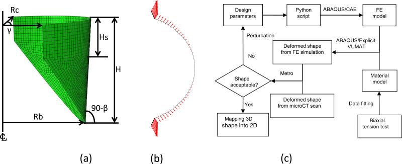
The geometrical design parameters for the ovine pulmonary valve were based on those established for the aortic valve leaflet due to their similarity in overall shape, and initially consisted of a cylindrical segment based on five parameters (Thubrikar, 1990). However the native pulmonary valve leaflets are not identical and the angle between two neighboring coaptation surfaces may vary around 120°. Rather than assuming perfect symmetric valve, so an angle [notdef] was utilized. In summary, six geometric parameters were utilized to define the leaflet geometry (Figure 2-a): the radius of the base Rb, the radius of the commissures Rc, the valve height H, the height of the commissures Hs, the angle of the open leaflet to vertical β, and the angle between two neighboring coaptation surfaces γ.
Figure 2.
(a) Schematic showing the six design parameters of unloaded leaflet, Rb: radius of the base, Rc: radius of the commissures, H: valve height, Hs: height of the commissures, β: angle of the open leaflet to vertical, γ: angle between two neighboring coaptation surfaces (Thubrikar, 1990). (b) Top down view of displacement applied on the leaflet attachment. (c) Design flowchart for optimal leaflet shape
2.5 Finite element simulations
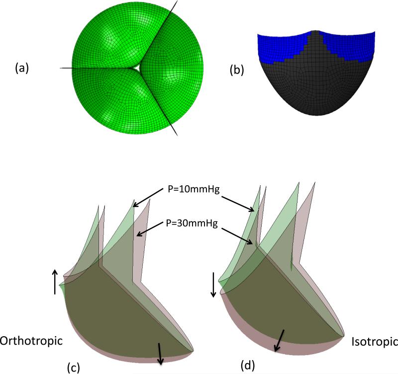
To simulate the deformation of ES-PEUU leaflet from fully opened to the fully loaded configuration ABAQUS/Explicit was used. The deformation of leaflet from fully open to closed is highly nonlinear and involves material and geometric nonlinearity, contact, and buckling. We thus choose the explicit method to simulate the quasi-static deformation since it avoids convergence issues of solving nonlinear equations common to implicit methods. In this study, only the anterior leaflet for replacement was modeled. The shape and the material properties of the native PV leaflets are not identical, and therefore the deformation of the three leaflets is not perfectly symmetric. Contact cannot thus be perfectly frictionless, so that inter-leaflet contact was assumed to be rigid and the friction coefficient is assumed to be 0.3 (Sun et al., 2005). A uniform pressure was applied on the leaflet surface and remained vertical to the surface as the leaflet deforms. The preferred material direction was aligned with the leaflet circumferential direction (CD). A single leaflet with uniform thickness (0.1 mm) was modeled using four-node quadrilateral finite strain shell elements in ABAQUS/Explicit, since this was the typical fabricated value. Dimensional changes in the valve root were modeled by applying displacements to the leaflet attachment in the cylindrical radial direction of PV (Fig. 2-b). The magnitude of the displacement was proportional to the loading pressure and varied linearly along the valve height. The basal point of leaflet attachment was assumed not to displace, with a set maximum displacement applied to the commissures of 0.7 mm and 2.1 mm for loading pressures 10 mmHg and 30 mmHg (to simulate hypertension), respectively.
To compare the simulated leaflet deformed shape to that of the native leaflet, the mean distance E between the two surfaces was defined to be
| (3) |
where S1 is the deformed surface of the simulated leaflet, S2 is the surface of leaflet from microCT scan, and d (p, S2) is the surface normal distance between a point p in S1 and the surface S2. We utilized the Metro (Cignoni et al., 1998) and MeshLab (http://meshlab.sourceforge.net/) to perform the calculations. In determining the optimal shape, we note that precise matching of the native PV is not a strict requirement for functional matching. Rather, we sought a shape that specifically allowed for:
Geometric matching of the coaptation and attachment regions, which are considered functionally required for normal leaflet function at full diastolic loading.
Maintain an overall approximation of the native PV leaflet shape, so that the optimal shape does not deviate substantially from the overall shape from the native PV. We set this to be no more than 10% of the average PV diameter at the root level, or ~2 mm.
The minimum mean value of surface error E.
The optimization flow started with the current design parameters passed to a Python script and used in ABAQUS/CAE scripting interface to create the FE model of leaflet automatically (Figure 2-c). The quasi-static deformation of leaflet under transvalvular physiological pressure was simulated, then the deformed shape of leaflet from the simulation was compared with the deformed native PV leaflet. The design parameters were perturbed and the above steps repeated until the optimal shape obtained.
In addition to the optimizations run above, we explored curvilinear fiber trajectories, which are well documented in heart valves (Joyce et al., 2009; Sacks et al., 1998). For these simulations, the preferred fiber orientation defined the local material axes with respect to the unloaded circumferential direction. The fiber direction changed gradually from the commissure region to the center region of leaflet, where it aligned in the circumferential direction. A range of orientations was chosen which ranged from 0° to 30° with respect to the commissures.
In vitro loaded shape validation
To insure geometric matching the original height of native leaflet was measured, and the ES-PEUU leaflet shape obtained by scaling the optimal 2D shape from FE simulation based on the ratio of leaflet height of the actual leaflet to be replaced. Note that the 2D cutout shape for replacement was obtained from the 3D initial shape while preserving the shape with no distortion or areal changes. The ES-PEUU biomaterial implant was constructed and the anterior leaflet of an ovine PV replaced ex-vivo. After excising the native anterior pulmonary valve leaflet, the ES-PEUU leaflet was sutured along the annulus using surgical 6-0 prolene sutures (Figs. 1-b,c). We then conducted a microCT scan of the loaded PV, with the deformed shape of the ES-PEUU leaflet reconstructed from the microCT images and compared with the deformed leaflet shape from FE simulation as described above.
Results
Optimization studies
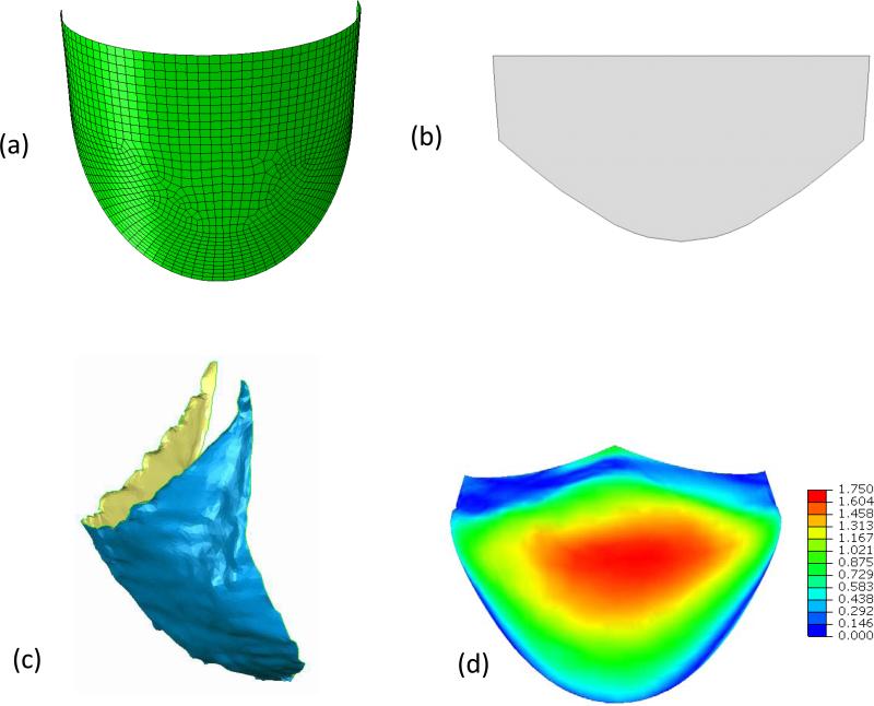
The Fung model fit the ES-PEUU data well, with r2 = 0.951 and 0.989 for orthotropic and isotropic ES-PEUU scaffold respectively (Table 1). We noted that for the isotropic scaffold the ratio of coefficients A1/A2=0.985, very close to the theoretical value of one; whereas the orthotropic scaffold exhibited the desired highly anisotropic response with A1/A2=15.405. These responses are known to bracket the current mechanical range for the ES-PEUU scaffolds (Courtney et al., 2006). Next, using the optimization flow process (Fig. 2-c), we determined an optimal undeformed shape for the orthotropic material consisting of the following geometric parameters: Rb=9.6mm, Rc=7.6mm, H=11.0mm, Hs=5.0mm, β=3°, and γ=133° (Table 2). The mean distance surface was 0.52 mm, with a range of 0 mm (located in the coaptation and leaflet attachment) to a maximum of 1.75 mm (located in the belly region) (Fig 3-d). We noted that the distance contour was not perfectly symmetric, due to natural asymmetries of the native leaflet. Utilizing the optimal 2D shape (Fig. 3-b), the reconstructed ES-PEUU leaflet (Fig. 3-c) compared favorably with the FE simulation, with a mean distance between the predicted and actual leaflet shapes of 0.76mm (a difference of +0.24 mm).
Table 1.
Material Parameters of ES-PEUU
| Material type | c (KPa) | A1 | A2 | A3 | A4 | A1/A2 | R2 |
|---|---|---|---|---|---|---|---|
| Orthotropic | 120.74 | 8.873 | 0.576 | 1.032 | 0.047 | 15.405 | 0.951 |
| Isotropic | 541.97 | 0.84 | 0.853 | 0.361 | 0.018 | 0.985 | 0.989 |
Table 2.
Simulation Parameters of Leaflet
Figure 3.
(a) The final optimized leaflet shape shown in 3D. (b) The final optimized leaflet shape shown “laid flat” in 2D. (c) The actual 3D reconstructed implanted leaflet at full diastolic loading. The mean error here was 0.72 mm, close to the simulation prediction.(d) Error in mm between the optimal leaflet and the 3D reconstructed leaflet shown in Fig. 1-c. The overall mean error was 0.52 mm and ranged from 0 mm to a maximum of 1.75 mm in the leaflet belly region.
Parametric simulations using a constant circumferential material axial direction
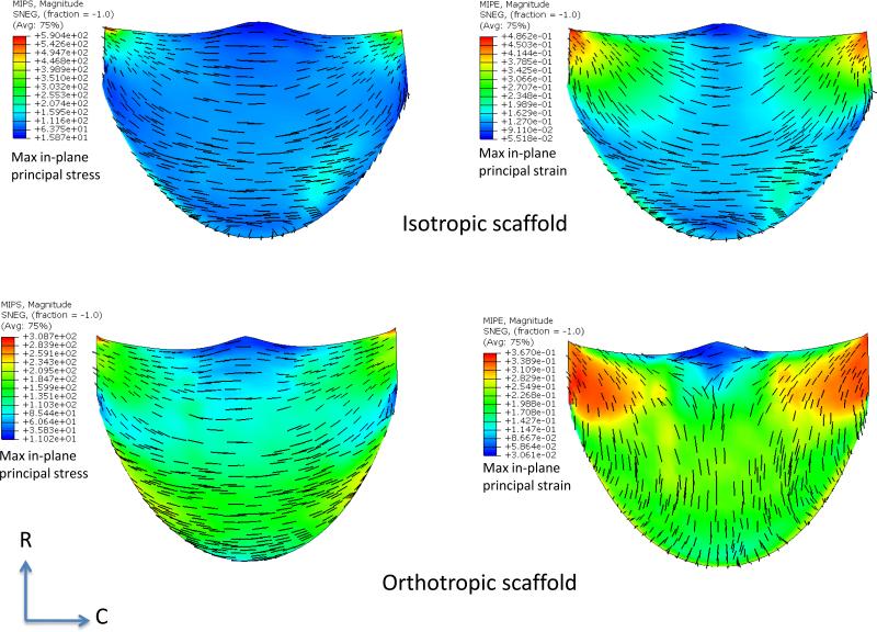
While a detailed presentation of the optimization process is beyond the scope of the present study, we noted the following key findings. For the orthotropic ES-PEUU material, we noted that the deformed position of the leaflet free edge was minimally affected by increasing transvalvular pressure (Fig. 4-c), whereas for the isotropic leaflet the center of the free edge of leaflet continued a downward displacement with increasing loading pressure (Fig. 4-d). Material anisotropy also had a profound effect on the resulting stress and strain distributions. For the isotropic ES-PEUU leaflet, the direction of maximum in-plane principal Cauchy stress in the center belly region remains in CD after deformation, with the principal stress direction near the commissure region rotating towards the belly region after deformation (Fig. 5). Note that the direction of maximum in-plane principal logarithmic strain coincided with direction of principal stress, as expected due to material isotropy. For the orthotropic leaflet, the maximum in-plane principal stress field was similar to the isotropic leaflet, whereas the direction of maximum in-plane principal strain in the center region was aligned to the radial direction after deformation (Fig. 5). Although the stress magnitude in radial direction is smaller than the corresponding circumferential stress, the corresponding radial strain was larger due to material anisotropy.
Figure 4.
(a) Copy and rotated top-down view of leaflet with 30mmHg pressure (b) Contact surface (in blue) of leaflet with 30mmHg. (c) Superimposed deformed shapes of leaflet under 10 mmHg and 30 mmHg pressures for orthotropic ES-PEUU leaflet (d) Superimposed deformed shapes of leaflet under 10 mmHg and 30 mmHg pressures for isotropic material models. Note the substantially smaller displacements in the orthotropic model simulation.
Figure 5.
Maximum in-plane principal stress (MIPS) and strain (MIPE) distributions for the isotropic and orthotropic material models for the simulations performed in Fig. 4. Perhaps the most striking difference is the switch in principal strain directions between the two material models. This is a direct result on how the leaflets deform from identical geometric starting points using the two different material models.
Optimal leaflet shape
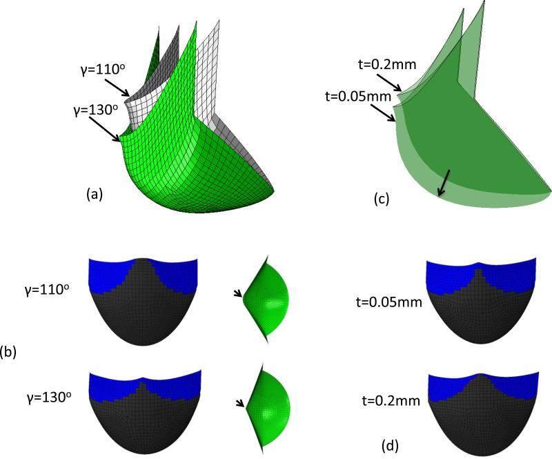
Optimal leaflet shape resulted from a specific combination of all design parameters for a specific leaflet material. Alterations with changes with the design parameters and leaflet thickness demonstrated substantial effects. For example, increasing the leaflet height H by 1.0 mm, the height of leaflet free edge center will increase 1.46 mm. Increasing Rb 0.8 mm resulted in the height of free edge center decreases by 0.39 mm. The height of free edge center will increase 0.28 mm if Rc is increased by 1.0mm. In addition, decreasing Rc or increasing Rb usually resulted in incomplete coaptation of leaflets. Increasing the angle β to 10° resulted in a folding leaflet in the deformed shape. This is important as analysis of the native PV leaflet geometry from the microCT scans demonstrated that the size and the shape of the three leaflets were not identical. We thus investigated the effects of varying the angle γ from 110° to 130° using the orthotropic material model. The simulations demonstrated that the angle of free edge with respect to horizontal plane increased 9.3° degree when the angle γ is increased from 110° to 130° (Fig. 6-a). The center of leaflet free edge with γ=110° was 2.13mm higher than that of leaflet with γ=130°. Keeping the initial shape of leaflet unchanged, the thickness was reassigned to be 0.05 mm and 0.2 mm. From simulation results, we observed that the coaptation surface of leaflet with 0.2 mm thickness was 0.67 mm higher than that of leaflet with 0.05mm thickness (Fig. 6-b). Overall, the least sensitive parameter was Hs, and the most sensitive parameters were H, β and γ.
Figure 6.
(a) Deformed shape of orthotropic ES-PEUU leaflet from simulation with γ=110° and γ=130° (b) Contact surface and top-down view of leaflet with γ=110° and γ=130° (c) Deformed shape of orthotropic ES-PEUU leaflet from simulation with t=0.2mm and t=0.05mm. (d) Contact surface of leaflet with t=0.2mm and t=0.05mm. Note the center of free edge is not in contact for leaflet with γ=110°.
Effects of curvilinear material axes
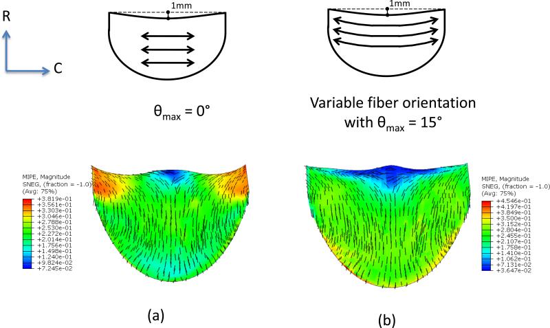
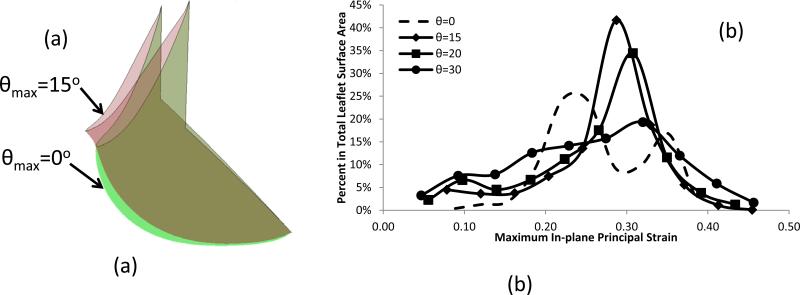
In initial simulations for leaflets with curvilinear fiber orientations we observed leaflet folding, which was removed by shortening the leaflet height from 11.0 mm to 10.0 mm (Fig. 7). Using this modified geometry, subsequent FE simulations indicated that the fiber orientation had a significant effect on the strain distribution and deformed shape (Figs. 7 and 8). Progressive changes in fiber orientation on strain distribution (θmax=0°, 15°, 20° and 30°, respectively) indicated that the most uniform strain distribution was obtained for θmax=15° (Figs. 7 and 8). Interestingly, the principal strain vector field directions were largely unaffected by alterations in fiber trajectories (Fig. 7)
Figure 7.
Maximum in-plane principal strain (MIPE) distribution of orthotropic ES-PEUU leaflet (a) with fiber orientation aligned in CD direction (b) with curvilinear fiber orientation.
Figure 8.
(a) Comparisons of the deformed shape of leaflet with different fiber orientation, and (b) Histogram for the comparisons of the strain distribution with different fiber orientation.
Discussion
Overview
While most simulations of heart valve design focus on stress analyses, the present study focused on the approximated reproduction of the fully loaded native PV leaflet shape. For the present study, we choose initial leaflet geometry, mechanical anisotropy, material axial directions, and thickness as the key parameters, since they are most amenable to leaflet fabrication. Perhaps the most interesting finding was that by starting with a relatively simple initial geometry and an elastomeric leaflet material, a leaflet like shape could be generated under physiological transvalvular pressure. While perhaps not encompassing the entire possible design parameter space, our results make it clear that relatively homogenous biomaterials can be used to develop anatomically realistic deformed leaflets. Moreover, even though the deformed geometry did not precisely match the actual leaflet (Fig. 3-d), our in-vitro validation study demonstrated good coaptation and no wrinkling or distortion (Fig. 3-c).
Overall, it was not necessary to precisely reproduce the native PV leaflet geometry to obtain a geometrically functional leaflet with a smooth stress distribution. Our simulation results also demonstrated that material anisotropy has a significant effect on leaflet deformation and stress distributions. To our knowledge, current curvilinear fiber trajectories using existing electrospun fabrication technologies have yet to be fully achieved. However, as fabrication technologies advance, the curvilinear fiber trajectory simulations suggest that this design feature may be useful in developing more uniform strain fields within the valve leaflet.
Limitations
We assumed that contact of the simulated leaflet with the other two native leaflets was rigid, so that contact surfaces were fixed. In reality, the contact is not absolutely rigid and the position of contact surfaces may move due to asymmetric shape and unequal size of leaflets. During actual surgery the leaflet is manually sutured, so that the leaflet may have already undergone slight deformations. However, the good agreement with the in-vitro validation suggests that the present surgical skill is sufficient that simulations can provide a good prediction of the final shape. Finally, we note that the present studies were only performed under quasi-static loading conditions; full fluid-structure interaction simulations will be needed to simulate full leaflet function over the complete cardiac cycle.
Conclusions
The focus of the current work was the deformed shape analysis, starting from a relatively simple and tractable initial geometry, of an elastomeric scaffold leaflet to functionally reproduce the shape of the ovine PV under full diastolic loading. While there have been related efforts in native and replacement heart valve modeling (Driessen et al., 2007; Einstein et al., 2010; Sacks et al., 2009a; Sun et al., 2005), our focus on shape as the primary metric makes the present effort unique. Moreover, our results lend support to the use of the single leaflet replacement model as a means to evaluate the complex requirements for heart valve biomaterials for pulmonary heart valve replacements. In particular, fabrication capabilities are currently limited; even the development of simple curvilinear fiber architectures (e.g. Fig. 7) have yet to be fully achieved in a wide variety of scaffolds. Most fabrication processes produce sheets of homogenous materials that, while flexible, cannot be shaped into complex surfaces readily. Thus, the present finding that complex deformed surfaces can be developed from relatively simple initial shapes will be intrinsically useful in the development of replacement heart valves.
The present approach is part of a larger need for systematic approaches, which becomes quite apparent when one considers the considerable issues in the development of engineered heart valve replacements (Mol et al., 2004; Sacks et al., 2009b; Schoen, 2008). Development of an engineered valved conduit, the ultimate goal for pediatric cardiovascular implant replacement for right ventricular outflow track replacements, requires functional matching of the valve leaflets, sinus, and pulmonary artery. Each of these structures is architecturally different and subjected to widely differing functional requirements. Thus, developments of these engineered tissue approaches will likely require separate efforts for each subcomponent. The present approach will be helpful in the design and analysis of leaflet biomaterials subjected to valve functional environment without the complicating effects of a particular valve or valved conduit design.
Acknowledgements
Funding for this work was supported by NIH Grants No. R01 HL68816 and HL089750. The authors would like to thank Nicholas Amoroso for fabricating ES-PEUU.
Footnotes
Publisher's Disclaimer: This is a PDF file of an unedited manuscript that has been accepted for publication. As a service to our customers we are providing this early version of the manuscript. The manuscript will undergo copyediting, typesetting, and review of the resulting proof before it is published in its final citable form. Please note that during the production process errors may be discovered which could affect the content, and all legal disclaimers that apply to the journal pertain.
Conflict of interests
The authors have no conflict of interests to report in this work.
References
- Beller CJ, Labrosse MR, Thubrikar MJ, Robicsek F. Role of aortic root motion in the pathogenesis of aortic dissection. Circulation. 2004;109:763–769. doi: 10.1161/01.CIR.0000112569.27151.F7. [DOI] [PubMed] [Google Scholar]
- Breuer C, Shin'oka T, Tanel R, Zund G, Mooney D, Ma P, Miura T, Colan S, Langer R, Mayer J, Vacanti J. Tissue Engineering Lamb Heart Valve Leaflets. Biotechnology and bioengineering. 1996;50:562–567. doi: 10.1002/(SICI)1097-0290(19960605)50:5<562::AID-BIT11>3.0.CO;2-L. [DOI] [PubMed] [Google Scholar]
- Cignoni P, Rocchini C, Scopigno R. Metro: Measuring error on simplified surfaces. Comput Graph Forum. 1998;17:167–174. [Google Scholar]
- Courtney T, Sacks MS, Stankus J, Guan J, Wagner WR. Design and analysis of tissue engineering scaffolds that mimic soft tissue mechanical anisotropy. Biomaterials. 2006;27:3631–3638. doi: 10.1016/j.biomaterials.2006.02.024. [DOI] [PubMed] [Google Scholar]
- Driessen NJ, Mol A, Bouten CV, Baaijens FP. Modeling the mechanics of tissue-engineered human heart valve leaflets. J Biomech. 2007;40:325–334. doi: 10.1016/j.jbiomech.2006.01.009. [DOI] [PubMed] [Google Scholar]
- Einstein DR, Del Pin F, Jiao X, Kuprat AP, Carson JP, Kunzelman KS, Cochran RP, Guccione JM, Ratcliffe MB. Fluid-Structure Interactions of the Mitral Valve and Left Heart: Comprehensive Strategies, Past, Present and Future. International journal for numerical methods in engineering. 2010;26:348–380. doi: 10.1002/cnm.1280. [DOI] [PMC free article] [PubMed] [Google Scholar]
- Fung YC. Biomechanics: Mechanical Properties of Living Tissues. 2nd ed. Springer Verlag; New York: 1993. [Google Scholar]
- Furukawa K, Ohteki H, Cao ZL, Doi K, Narita Y, Minato N, Itoh T. Does dilatation of the sinotubular junction cause aortic regurgitation? Ann Thorac Surg. 1999;68:949–953. discussion 953-944. [PubMed] [Google Scholar]
- Joyce EM, Liao J, Schoen FJ, Mayer JE, Jr., Sacks MS. Functional collagen fiber architecture of the pulmonary heart valve cusp. Ann Thorac Surg. 2009;87:1240–1249. doi: 10.1016/j.athoracsur.2008.12.049. [DOI] [PMC free article] [PubMed] [Google Scholar]
- Mol A, Bouten CV, Baaijens FP, Zund G, Turina MI, Hoerstrup SP. Review article: Tissue engineering of semilunar heart valves: current status and future developments. J Heart Valve Dis. 2004;13:272–280. [PubMed] [Google Scholar]
- Sacks MS, David Merryman W, Schmidt DE. On the biomechanics of heart valve function. J Biomech. 2009a;42:1804–1824. doi: 10.1016/j.jbiomech.2009.05.015. [DOI] [PMC free article] [PubMed] [Google Scholar]
- Sacks MS, Schoen FJ, Mayer JE., Jr Bioengineering Challenges for Heart Valve Tissue Engineering. Annual Review of Biomedical Engineering. 2009b;11 doi: 10.1146/annurev-bioeng-061008-124903. [DOI] [PubMed] [Google Scholar]
- Sacks MS, Smith DB, Hiester ED. The aortic valve microstructure: effects of transvalvular pressure. Journal of Biomedical Materials Research. 1998;41:131–141. doi: 10.1002/(sici)1097-4636(199807)41:1<131::aid-jbm16>3.0.co;2-q. [DOI] [PubMed] [Google Scholar]
- Schoen FJ. Evolving concepts of cardiac valve dynamics: the continuum of development, functional structure, pathobiology, and tissue engineering. Circulation. 2008;118:1864–1880. doi: 10.1161/CIRCULATIONAHA.108.805911. [DOI] [PubMed] [Google Scholar]
- Shinoka T, Breuer CK, Tanel RE, Zund G, Miura T, Ma PX, Langer R, Vacanti JP, Mayer JE., Jr. Tissue engineering heart valves: valve leaflet replacement study in a lamb model. Ann Thorac Surg. 1995;60:S513–516. doi: 10.1016/0003-4975(95)00733-4. [DOI] [PubMed] [Google Scholar]
- Shinoka T, Ma PX, Shum-Tim D, Breuer CK, Cusick RA, Zund G, Langer R, Vacanti JP, Mayer JE., Jr. Tissue-engineered heart valves. Autologous valve leaflet replacement study in a lamb model. Circulation. 1996;94:II164–168. [PubMed] [Google Scholar]
- Sodian R, Hoerstrup SP, Sperling JS, Daebritz SH, Martin DP, Schoen FJ, Vacanti JP, Mayer JE., Jr. Tissue engineering of heart valves: in vitro experiences. Ann Thorac Surg. 2000;70:140–144. doi: 10.1016/s0003-4975(00)01255-8. [DOI] [PubMed] [Google Scholar]
- Stankus JJ, Guan J, Fujimoto K, Wagner WR. Microintegrating smooth muscle cells into a biodegradable, elastomeric fiber matrix. Biomaterials. 2006;27:735–744. doi: 10.1016/j.biomaterials.2005.06.020. [DOI] [PMC free article] [PubMed] [Google Scholar]
- Stankus JJ, Guan J, Wagner WR. Fabrication of biodegradable elastomeric scaffolds with sub-micron morphologies. J Biomed Mater Res. 2004;70A:603–614. doi: 10.1002/jbm.a.30122. [DOI] [PMC free article] [PubMed] [Google Scholar]
- Sun W, Abad A, Sacks MS. Simulated bioprosthetic heart valve deformation under quasi-static loading. Journal of Biomechanial Engineering. 2005;127:905–914. doi: 10.1115/1.2049337. [DOI] [PubMed] [Google Scholar]
- Swanson WM, Clark RE. Dimension and geometric relationships of the human valve and function of pressure. Circ Res. 1974;35:871–882. doi: 10.1161/01.res.35.6.871. [DOI] [PubMed] [Google Scholar]
- Thubrikar M. The Aortic Valve. CRC; Boca Raton: 1990. [Google Scholar]
- Thubrikar M, Piepgrass WC, Shaner TW, Nolan SP. The design of the normal aortic valve. Am J Physiol. 1981;241:H795–801. doi: 10.1152/ajpheart.1981.241.6.H795. [DOI] [PubMed] [Google Scholar]


