Abstract
A DNA configuration switch was designed to fabricate a reversible and regenerable Raman-active substrate. The substrate is composed of an Au film and hairpin-shaped DNA strand (hot spot generation probes, HSGPs) labeled with dye-functionalized silver nanoparticle (AgNP). Another ssDNA that recognizes a specific trigger was used as an antenna. The HSGPs are immobilized on the Au film to draw the dye-functionalized AgNPs close to the Au surface and create an intense electromagnetic field. Hybridization of HSGP with the two arm segments of the antenna forms a triplex-stem structure to separate the dye-functionalized AgNP from the Au surface and cause a quenching of the Raman signal. Interaction with its trigger leads to release of the antenna from the triplex-stem structure, and the hairpin structure of the HSGP is restored, thereby creating an effective “off” to “on” state of the Raman signal. Nucleic acid sequence associated with the HIV-1 U5 long terminal repeat sequences and ATP are used as the triggers. The substrate shows excellent reversibility, reproducibility and controllability of SERS effects, which are significant requirements for practical SERS sensor applications.
In the past two decades, surface-enhanced Raman scattering (SERS) has been developed into a significant technique in biomedical analysis because of its single-molecule sensitivity, molecular specificity, and insensitivity to quenching.1–3 These distinct advantages have led to the development of a number of ingenious SERS-based biosensors to identify and detect an array of biological analytes, including small bioactive molecules,4, 5 DNA6–8 and proteins,9, 10 and even cells.11 To achieve maximum enhancement of the Raman signal, current research is focused on fabricating metallic substrates for generation of hot geometries (hot spots), either using the metal surface morphology or two metal nanoparticles,12–17 which led to enormous Raman enhancement factors on the order of 1014-1015. Another key requirement of any SERS substrate for practical sensor applications is the reversibility and reproducibility. However, hot spot-active substrates fabricated by traditional methods are irreversible and not regenerable, making the sensor usable only once. Fabrication of reversible and regenerable SERS-active substrates for biosensors is thus highly desirable, but remains a challenge, and to the best of our knowledge, no such a substrate is reported in the literature.
Herein we report a new approach for facile fabrication of reversible and regenerable hot spots-active substrate through the controlled organization of silver nanoparticles (AgNPs) on an Au film surface with a specially designed DNA molecular switch. Recent developments in DNA-based nanotechnology provide an attractive way to organize both metallic and semiconducting nanoparticles into periodic structures through programmable base-pairing interactions.18, 19 Using species such as DNA or antibody-antigen interactions to control the enhancement of Raman scattering, assembly of metallic nanoparticles through biomolecular recognition has been extensively studied in recent years.6–9, 20–22 Chemically, the great majority of the reported approaches relies on a dyelabeled DNA that binds to a trigger to alter the conformation of the DNA and produce the desired SERS signal. Being quite different from previously reported approaches, our active substrate involves an antenna that specifically binds to a trigger and a hot spot-generation probe (HSGP), these two moieties are assembled together through a triplex DNA structure, and hot spot is created by configuration conversion of the AgNPs-functionalized HSGP on the Au surface.
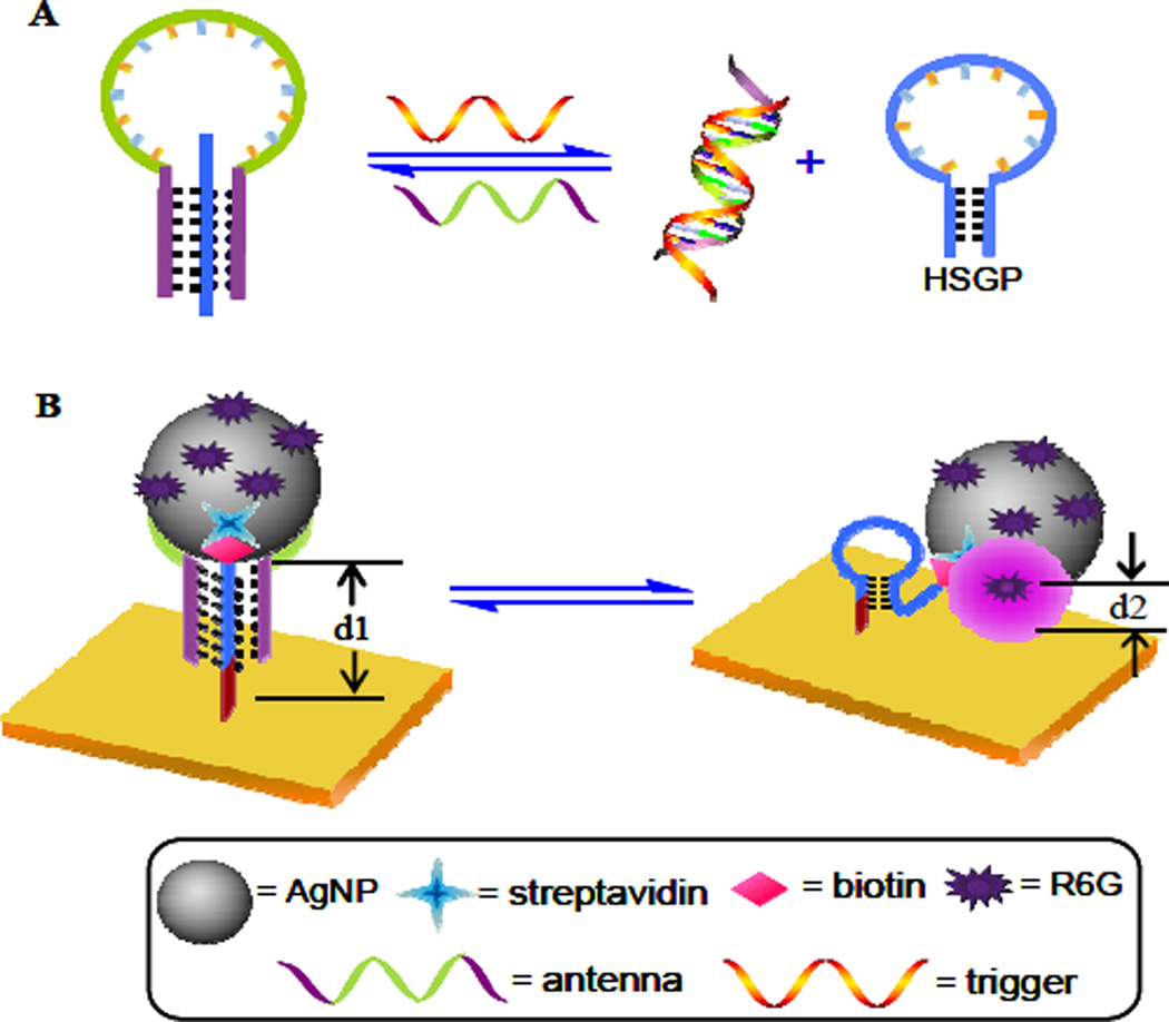
The fundamental concept of this approach is illustrated in Scheme 1. In our design, a central, trigger-specific single-strand (-ss) DNA (in green) flanked by two arm segments (in purple) is used as an antenna, while a hairpin-shaped oligonucleotide (in blue) serves as the HSGP, and rho-damine 6G(R6G) was selected as the Raman reporter. The HSGP is functionalized with AgNPs. Once the HSGP is bound with the two arm segments of the antenna via Watson-Crick and Hoogsteen base pairings,23, 24 a “triplex-stem” structure is formed, in which the HSGP remains an “open” configuration. In this state, the R6G-functionalized AgNPs are physically separated from Au surface, resulting in the SERS signal “off” state (low SERS effect). Conversely, upon binding with its trigger, the antenna is released from the triplex-stem structure and the HSGP restores its “duplex-stem” cyclic structure, bringing the AgNPs into proximity to the Au film surface to enhance the electromagnetic field,25, 26 and produce a very large SERS signal “on” state.
Scheme 1.
Working principle of the DNA nanomachine-directed reversible SERS active substrate: (A) Structure switch of HSGP between an open and a hairpin-shaped configuration alternative induced by the trigger DNA and the antenna. (B) The corresponding reversible SERS “hot spot” generation through assembly and disassembly of AgNPs on an Au film surface.
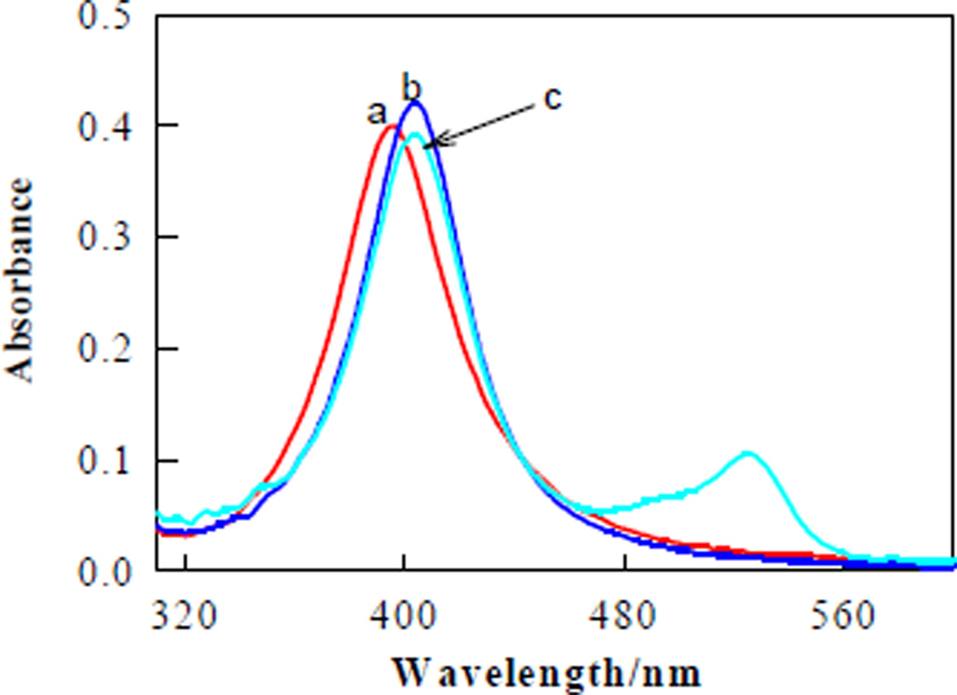
For formation of the SERS-hot spot substrate, AgNPs were prepared according to a reported method.27 The TEM image shows the formed AgNPs with size distribution from 15 to 20 nm, but most were 18 nm (Figure S1, Supporting Information). The UV-vis absorption spectrum shows a λmax of 398 nm (Figure 1, curve a), which is attributed to the surface plasmon resonance of small AgNPs.28 The AgNPs were first functionalized with streptavidin and then encoded with thiol-DNA-modified R6G (5'-thiol-TTTTT-R6G-3'). After such modifying, a slight red shift of ~7 nm is observed (curve b). When the streptavidin-functionalized AgNPs were encoded with R6G molecules, an additional absorption peak at 526 nm, the λmax of R6G, clearly appears (curve c). The surface coverage of R6G molecules on AgNP was evaluated to be 13.5 ± 1.2 pmol/cm2.29 The stability of streptavidin/R6G-functionalized AgNPs was examined by measuring changes in the plasmon band absorbance under a wide range of NaCl concentrations. The functionalized AgNPs can be subjected to high ionic strengths (Figure S2, Supporting Information).
FIGURE 1.
UV-vis absorption spectra of AgNPs (a), streptavidin-functionalized AgNPs and (b), streptavidin/R6G-functionalized AgNPs (c) in PBS.
To assemble the streptavidin/R6G-functionalized AgNPs onto an Au film surface, a 36-base ssDNA (5'-biotin-CCTCCAGA GAGAGAGAGAGAGGGAGGAAAAAAAAAAthiol-3') was designed and used as HSGP. This DNA strand has a hairpin structure, including a 5-base pair stem and a 16-base loop sequence of repeating adenine and cytosine nucleotides, as well as poly(dA)10 at the 3'-end. Melting temperature measurement (Tm) indicates that this hairpin structure has moderate thermal stability with a Tm value of 40°C (Figure S3, Supporting Information). The HSGP was then biotinylated at the 5'-end and immobilized on the Au film surface through 3'-endthiol. The surface coverage of the HSGP on the Au surface was determined to be 10.2 ± 0.8 pmol/cm2.29 The Au film was subsequently treated with thiolated poly(dT)10 to prevent other species from binding to free Au surface sites and to keep the HSGP standing fairly erect by forming an A-T duplex with the HSGP. The R6G-functionalized AgNPs were then attached to the 5'-end of the HSGP through specific streptavidin-biotin interaction.
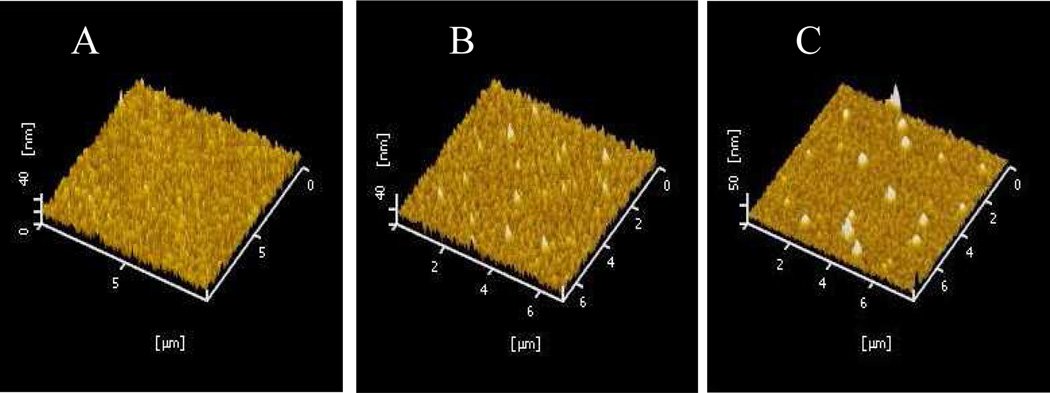
Atomic force microscopy (AFM) images were used to characterize the surface features of the Au film treated with AgNPs-functionalized HSGP and “triplex-stem” DNA, respectively. The image shows that the pure Au film prior to treatment with HSGP had a mean height of ~10 nm, and no obvious bright spots were observed (Figure 2A), indicating that the Au surface is enough smooth. After AgNPs were assembled on the Au film through HSGP, a few bright spots appeared in the image (Figure 2B), and the height was ~30 nm (d2, Scheme 1B). The ~18 nm of AgNPs, together with the 6-nm length of streptavidin plus the DNA strand, would create features with topographic heights between 25 and 35 nm. When HSGP was initially hybridized with the antenna, the open configuration of the 26-base HSGP increased the height by ~10 nm, AFM images appear as many new bright spots (Figure 2C) with a mean height of 40 nm (d1, Scheme 1B).
FIGURE 2.
AFM topographic images of the bare Au film (A), the Au film bonded with streptavidin/ R6G-functionalized AgNPs through HSGP (B), and as in (B), but treated with P1 to form triplex-stem cyclic DNA (C).
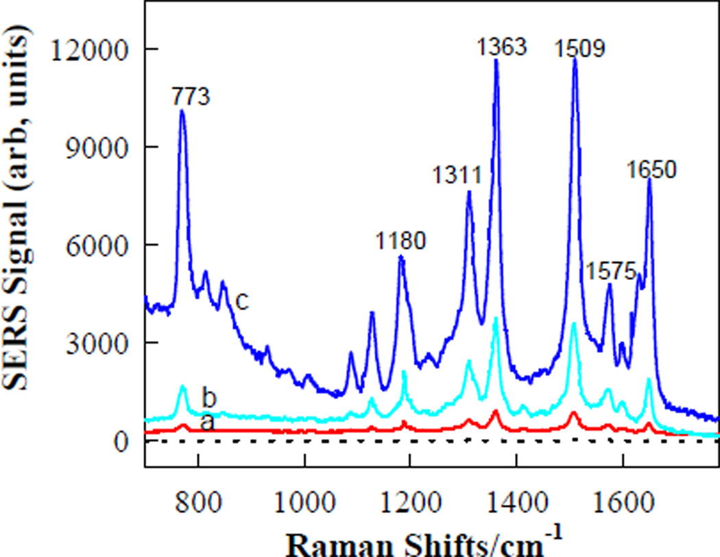
To test the feasibility of this approach as a SERS-active substrate, hot spot creation was first examined using a 21-mer ssDNA (T1, 5'-ACTGCTAGA GATTTTCCACAT-3') from the HIV-1 U5 long terminal repeat (LTR) as the trigger. The antenna (P1, 5'-TCTCTCTCATGTGGAAAATCTCTAGCAGT CTCTCTCT-3') was designed to contain 21 bases in the middle that were identical to complementary of T1, and two arm segments to bind the loop sequence of the HSGP to form a triplex motif through forming T-A•T and C-G•C base triplets.23 The sequences of the two arm segments were optimized to achieve the largest SERS signal enhancement (Figure S4 and Figure S5, Supporting Information). Figure 3 shows a set of SERS spectra of the R6G molecules that are attached on the AgNPs upon adding T1 in sodium phosphate buffer (PBS, pH 5.2, 20 mM NaCl and 2.5 mM MgCl2). This pH was obtained by optimization to achieve the best response sensitivity (Figure S6, Supporting Information). As expected, starting with the triplex-stem state, the SERS signals are very weak, indicating that the R6G-functionalzied AgNPs are far away from the Au surface, so that no hot spot can be generated. Hybridization of P1 with T1 leads to release of P1 from HSGP so that the HSGP forms its initial duplex-stem cyclic structure, allowing the AgNPs to approach the Au film more closely, thereby increasing the electromagnetic field concentration in the SERS hot spot. As a result, a strong SERS signal is observed. The spectrum characteristics are the same as those obtained for rhodamine dyes adsorbed on metallic surfaces.30 The SERS enhancement of the most prominent Raman peak at 1509 cm−1 is estimated to be 23.6-fold upon P1 hybridization to 1.0 µM T1. While in the presence of 1.0 µM a single-base mismatch sequence (MT1, 5'-ACTGCTAGATATTTTCCACAT-3'), the value of SERS intensity enhancement was approximately 8.7-fold under the same conditions, demonstrating the specificity and selectivity of this approach and its application in selective diagnostics. Controlled experiment shows that no measurable Raman signal is observed when HSGP was labeled with R6G at 5′-end and then immobilized on the Au surface (dashed line of Figure 3), According to literature methods,32,33 an enhancement factor of ~2.14 × 10⁵ was determined (For details, see Supporting Information), indicating that no distinct Raman scattering signal could be detected without Ag-dependent electromagnetic field enhancement.31
FIGURE 3.
SERS spectra of the active substrate composed of R6G-functionalized AgNPs-on-Au film and P1 in PBS in the absence (a), and presence of MT1 (b) and T1(c). Dashed line is SERS of R6G-labeled HSGP immobilized on the Au film. The concentrations of MT1 and T1 are 1.0 µM, respectively.
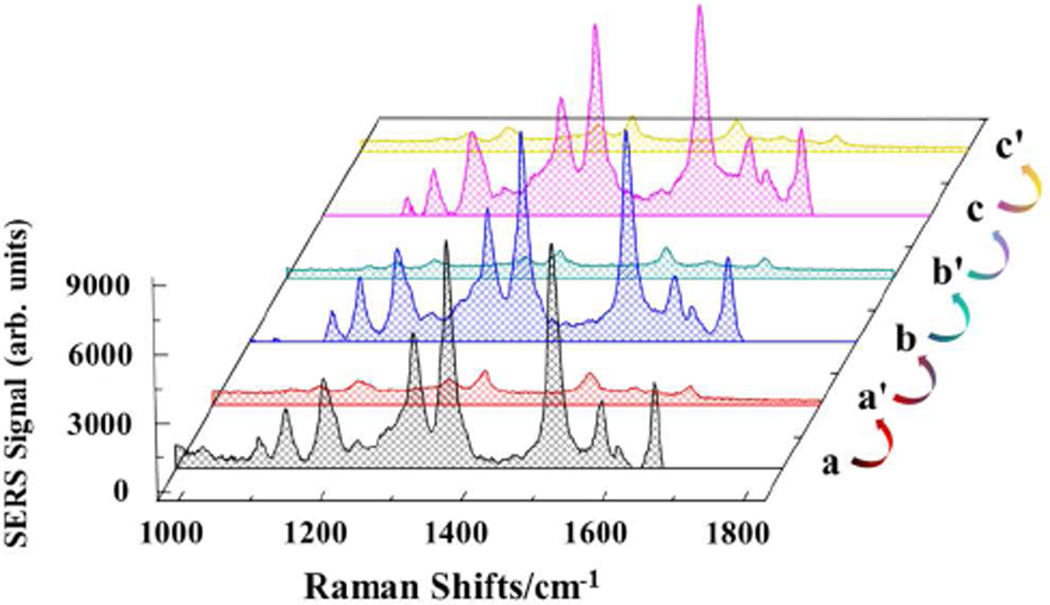
Because of the strong interactions between DNA and its target, the most routinely designed generation of SERS hot spots by DNA interaction is irreversible. In our approach, the DNA hybridization and SERS hot spot generation occur separately. Therefore, opening the hairpin structure of HSGP upon rehybridization with P1 eliminates the electromagnetic field and hot spot generating ability, thus illustrating the controlled “on” and “off” switching of Raman signals. To demonstrate, hybridization of P1 with T1 produces a large SERS intensity enhancement (Figure 4). Washing the Au film with PBS and subsequently immersing the Au film in the P1 solution allows the HSGP to rehybridize and restores its overall geometry to the degree required to return the SERS spectrum to its pre-exposure form. The reproducibility and reversibility of active-substrate are achieved by sequentially exposing the Au film to T1 and P1 solutions. The mean SERS intensity values of the 1509 cm−1-band with their confidence intervals were found to be 9070.7± 299.1(n = 5, 100 nM T1) and 807.8 ± 38.2 (n = 5, 1.0 µM P1), respectively. The reversibility is related to AgNPs size. When the hydrodynamic diameter of AgNPs is > 60 nm, the HSGP can not return its triplex-stem structure upon hybridization with P1 (data not shown). Nevertheless, compared to most reported methods that used DNA for the preparation of SERS substrate, our strategy, employing configuration conversion of HSGP between “open” and “duplex-stem” cyclic structure, thus provides advantages in terms of controllability and reproducibility.
FIGURE 4.
SERS spectra of the Au film after several repeated concentration step changes between 100 nM T1 (traces a, b and c) and 1.0 µM P1 (traces a', b' and c'). The SERS spectrum was returned to its pre-exposure form by first washing with PBS 3 times and then immersing in the P1 solution for 2.0 h.
To demonstrate the universality of this design, hot spot creation by small molecule interaction was studied by using adenosine triphosphate (ATP) as the trigger and the anti-ATP-binding aptamer (P2, 5'-CCTCTCTCACCTGGGGGAGTA TTGCGGAGGAAGGTCTCTCTCC-3')34,35 as the antenna. P2 is composed of DNA sequences for ATP and two arm segments of d(TC)6 that are complementary to the central sequence of the HSGP. In the absence of ATP, the triplex-stem structure enables high SERS-quenching efficiency. But, in the presence of ATP in the sample solution, significant SERS signal enhancement is observed (Figure S7, Supporting Information). The corresponding surface features of the Au film were characterized with AFM mages (Figure S8, Supporting Information). To demonstrate the potential of applying the SERS hot spot for quantitative bioanalysis, the peak intensity at 1509 cm−1 was compared to the concentration of ATP (Figure S9A, Supporting Information), revealing that the SERS signal increased with the increase in ATP concentration. Initially, the peak’s intensity increased approximately 1.3-fold when 50 nM ATP was introduced. However, with an ATP concentration of 4.0 µM, the intensity increased 19-fold, the observed saturation level (Figure S9B, Supporting Information). The SERS intensity increases linearly with the increase of ATP concentration between 25 nM and 2.0 µM (R2 = 0.988). The detection limit of 50 nM ATP is below the dissociation constant of anti-ATP-binding (Kd ≈ 6 µM).32,33 This can be attributed to the occurrence of signal amplification by the ability of one, or more likely, two ATP molecules to bring about one HSGP structural change, while the SERS spectrum originates from the many tens of R6G molecules in the region of the hot spot.
Finally, it is noteworthy that another way to create the active substrate is direct hybridization of an antenna with HSGP to form a dsDNA structure, and dehybridization when the antenna binds to a trigger. While this strategy offers a means of SERS hot spot generation, it suffers from an intrinsic limitation, because the HSGP is antenna sequence-dependent, in order to achieve suitable hybridization without hindering the recognition and affinity of antenna toward its trigger, optimization of the HSGP sequence length is often involved. This optimization requires preparation of several different hot spot substrates, which means that the method would not qualify as a general approach for hot spot generation.
In summary, a reversible and regenerable SERS hot spot-active substrate was fabricated by employing DNA- and Raman dye-functionalized AgNPs on an Au film surface. On the basis of a configurational switch between an “open” and a “duplex-stem” cyclic DNA structure, the hot spot effectively switches from an “off” to “on” signal state following the action of a biological recognition event. Compared to known SERS hot spot substrates, the present approach shows excellent reversibility, reproducibility, and controllability of SERS effects, which are significant requirements for practical SERS applications. Nucleic acid sequences associated with the LTR and ATP were used to induce hot spot generation, which, by virtue of the ability to alter the antenna sequence, is applicable to other nucleic acids, proteins, and small molecules for biomedical applications. Therefore, this hot spot generation strategy can be considered as a universal method and opens new opportunities toward the development of more practical SERS detection systems.
Supplementary Material
ACKNOWLEDGMENT
The work was supported by NSFC (21005026 and 21135001), DFMEC (20100151120008, 20110161110006), ‘973’ National Key Basic Research Program (2011CB911000). It is also supported by grants awarded by the US National Institutes of Health (GM066137, GM079359 and CA133086), and by China National Instrumentation Program 2011YQ03012412, and by the special fund of Chongqing key laboratory.
Footnotes
ASSOCIATED CONTENT
Supporting Information. Experimental details including sample preparation, instrumentation and experimental results, as well as additional information as noted in text. This material is available free of charge via the Internet at http://pubs.acs.org.
The authors declare no competing financial interest.
REFERENCES
- 1.Fleischmann M, Hendra PJ, McQuillan AJ. J. Phys. Lett. 1974;26:163–166. [Google Scholar]
- 2.Albrecht MG, Creighton JA. J. Am. Chem. Soc. 1977;99:5215–5217. [Google Scholar]
- 3.Stacy AM, Van Duyne RP. Chem. Phys. Lett. 1983;102:365–370. [Google Scholar]
- 4.Shafer-Peltier KE, Haynes CL, Glucksberg MR, Van Duyne RP. J. Am. Chem. Soc. 2003;125:588–593. doi: 10.1021/ja028255v. [DOI] [PubMed] [Google Scholar]
- 5.Kim NH, Lee SJ, Moskovits M. Nano Lett. 2010;10:4181–4185. doi: 10.1021/nl102495j. [DOI] [PubMed] [Google Scholar]
- 6.Cao CY, Jin R, Mirkin CA. Science. 2002;297:1536–1540. doi: 10.1126/science.297.5586.1536. [DOI] [PubMed] [Google Scholar]
- 7.Qian X, Zhou X, Nie SM. J. Am. Chem. Soc. 2008;130:14934–14935. doi: 10.1021/ja8062502. [DOI] [PMC free article] [PubMed] [Google Scholar]
- 8.Kang T, Yoo SM, Yoon I, Lee SY, Kim B. Nano Lett. 2010;10:1189–1193. doi: 10.1021/nl1000086. [DOI] [PubMed] [Google Scholar]
- 9.Cao YC, Jin RC, Nam JM, Thaxton CS, Mirkin CA. J. Am. Chem. Soc. 2003;125:14676–14677. doi: 10.1021/ja0366235. [DOI] [PubMed] [Google Scholar]
- 10.Bonham AJ, Btaun G, Pavel I, Moskovits M, Reich NOCA. J. Am. Chem. Soc. 2007;129:14572–1414573. doi: 10.1021/ja0767837. [DOI] [PubMed] [Google Scholar]
- 11.Kneipp J, Kneipp H, Rice WI, Kneipp K. Anal. Chem. 2005;77:2381–2385. doi: 10.1021/ac050109v. [DOI] [PubMed] [Google Scholar]
- 12.Lee SJ, Morrill AR, Moskovits M. J. Am. Chem. Soc. 2006;128:2200–2201. doi: 10.1021/ja0578350. [DOI] [PubMed] [Google Scholar]
- 13.Kang T, Yoon I, Jeon KS, Choi W, Lee Y, Seo K, Yoo Y, Park QH, Ihee H, Suh YD, Kim B. J. Phys. Chem. C. 2009;113:7492–7496. [Google Scholar]
- 14.Shegai T, Vaskevich A, Rubinstein I, Haran G. J. Am. Chem. Soc. 2009;131:14390–14398. doi: 10.1021/ja904480r. [DOI] [PubMed] [Google Scholar]
- 15.Li JF, Huang YF, Ding Y, Yang ZL, Li SB, Zhou XS, Fan FR, Zhang W, Zhou ZY, Wu DY, Ren B, Wang ZL, Tian ZQ. Nature. 2010;464:392–395. doi: 10.1038/nature08907. [DOI] [PubMed] [Google Scholar]
- 16.Rycenga M, Xia XH, Moran CH, Zhou F, Qin D, Li ZY, Xia YA. Angew. Chem. Int. Ed. 2011;50:5473–5477. doi: 10.1002/anie.201101632. [DOI] [PMC free article] [PubMed] [Google Scholar]
- 17.Wei KK, Xiang SZ, Malini O. Anal. Chem. 2012;84:908–916. doi: 10.1021/ac201712k. [DOI] [PubMed] [Google Scholar]
- 18.Aldaye FA, Palmer AL, Sleiman HF. Science. 2008;321:1795–1799. doi: 10.1126/science.1154533. [DOI] [PubMed] [Google Scholar]
- 19.Sharma J, Chhabra R, Cheng A, Brownel J, Liu Y, Yan H. Science. 2009;323:112–116. doi: 10.1126/science.1165831. [DOI] [PMC free article] [PubMed] [Google Scholar]
- 20.Graham D, Thompson DG, Ewen Smith TW, Faulds K. Nat. Nanotechnol. 2008;3:548–551. doi: 10.1038/nnano.2008.189. [DOI] [PubMed] [Google Scholar]
- 21.Kim NH, Lee SJ, Moskovits M. Adv. Mater. 2011;23:4152–4156. doi: 10.1002/adma.201101847. [DOI] [PubMed] [Google Scholar]
- 22.Zhang ZL, Wen YQ, Ma Y, Luo J, Zhang XY, Jiang L, Song YL. Appl. Phys. Lett. 2011;98:133704. [Google Scholar]
- 23.Salunkhe M, Wu TF, Letsinger RL. J. Am. Chem. Soc. 1992;114:8768–8772. [Google Scholar]
- 24.Zheng J, Li JS, Jiang Y, Jin JY, Wang KM, Yang RH, Tan WH. Anal. Chem. 2011;83:6586–6592. doi: 10.1021/ac201314y. [DOI] [PubMed] [Google Scholar]
- 25.Xu H, Aizpurua J, Käll M, Apell P. Phys. Rev. E. 2000;62:4318–4324. doi: 10.1103/physreve.62.4318. [DOI] [PubMed] [Google Scholar]
- 26.Moskovits M, Tay L, Yang J, Haslett T. Top. Appl. Phys. 2002;82:215. [Google Scholar]
- 27.Lee P, Meisel DJ. J. Phys. Chem. 1982;86:3391–3395. [Google Scholar]
- 28.Kelly KL, Coronado E, Zhao LL, Schatz GC. J. Phys. Chem. B. 2003;107:668–677. [Google Scholar]
- 29.Demers LM, Mirkin CA, Mucic RC, Reynolds RA, Letsinger RL, Elghanian R, Viswanadham G. Anal. Chem. 2000;72:5535–5541. doi: 10.1021/ac0006627. For details see supporting information. [DOI] [PubMed] [Google Scholar]
- 30.Jiang J, Bosnick K, Maillard M, Brus L. J. Phys. Chem. B. 2003;107:9964–9972. [Google Scholar]
- 31.Cao YC, Jin R, Mirkin CA. Science. 2002;297:1536–1540. doi: 10.1126/science.297.5586.1536. [DOI] [PubMed] [Google Scholar]
- 32.Braun G, Lee SJ, Dante M, Nguyen TQ, Moskovits M, Reich N. J. Am. Chem. Soc. 2007;129:6378–6379. doi: 10.1021/ja070514z. [DOI] [PubMed] [Google Scholar]
- 33.Yan J, Su S, He SJ, He Y, Zhao B, Wang DF, Zhang HL, Huang Q, Song SP, Fan CH. Anal. Chem. 2012 doi: 10.1021/ac301809e. dx.doi.org/10.1021/ac301809e. [DOI] [PubMed] [Google Scholar]
- 34.Huizenga DE, Szostak JW. Biochemistry. 1995;34:656–665. doi: 10.1021/bi00002a033. [DOI] [PubMed] [Google Scholar]
- 35.Urata H, Nomura K, Wada S, Akagi M. Biochem. Biophys. Res. Commun. 2007;360:459–463. doi: 10.1016/j.bbrc.2007.06.075. [DOI] [PubMed] [Google Scholar]
Associated Data
This section collects any data citations, data availability statements, or supplementary materials included in this article.


