Abstract
Radiofrequency ablation (RFA) may be an option for patients with lung tumors who have unresectable disease and are not suitable for available palliative modalities. RFA electrode positioning may take several attempts, necessitating multiple imaging acquisitions or continuous use of CT (Computed Tomography). Electromagnetic tracking utilizes miniature sensors integrated with RFA equipment to guide tools in real-time, while referencing to pre-procedure imaging. This technology was demonstrated successfully during a lung tumor ablation, and was more accurate at targeting the tumor, compared to traditional freehand needle insertion. It is possible, although speculative and anecdotal, that more accuracy could prevent unnecessary repositioning punctures and decrease radiation exposure. Electromagnetic tracking has theoretical potential to benefit minimally invasive interventions.
Keywords: electromagnetic tracking, radiofrequency ablation, RFA, lung, tumor
Introduction
Radiofrequency Ablation (RFA) is increasingly utilized as a non-surgical option in the management of primary and secondary lung tumors [1]. RFA in the lung often has minimal adverse effects with predicable outcomes [1,2]. With conventional percutaneous RFA techniques, determining the required needle size, type, position of needle puncture, trajectory, and number of ablations is based upon a pre-procedural and/or multiple peri-procedural computed tomography (CT) scans. This process is non-standardized, and requires the interventional radiologist to develop a mental 3D map to guide the ablation process. Accurate needle placement can be difficult, even with ideal image guidance. In addition, prolonged use of CT or fluoroscopy during image acquisition exposes the patient (and potentially the operator) to ionizing radiation.
Electromagnetic tracking (EMT) of inner needle tips is a new application for real-time needle-tip positioning that is used in conjunction with standard imaging modalities. It has been enabled by the development of miniaturized sensor coils that can be embedded within the needle itself. Electromagnetic tracking requires creating an electromagnetic field around the anatomic region of interest (Figure 1a). A weak current is induced within the coil when an instrument moves within this electromagnetic field. The current inrelation to multiple magnetic generators is detected by a computer and processed into reproducible, position coordinates. This location can be overlaid (in a software process known as “registration”) upon prior CT, magnetic resonance or positron emission tomography for real-time navigation during RFA [3]. Analysis of such an electromagnetic tracking system in a previous 20 patient case series has demonstrated the accuracy of this system in retrospectively correlating virtual needle position with actual needle position during conventional freehand needle insertion. The minimal extra time required to set up the system was also documented [4]. The relative accuracy of this technique compared to freehand needle insertion is shown. Also, the ability of an electromagnetic tracking system to prospectively guide needle insertion under clinical circumstances without the use of regular imaging input is assessed in this case.
Fig. 1.
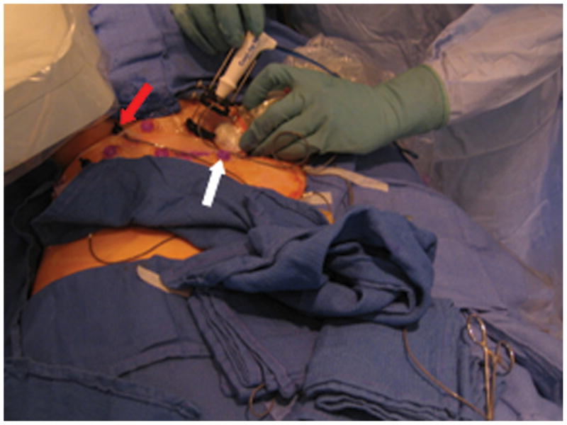
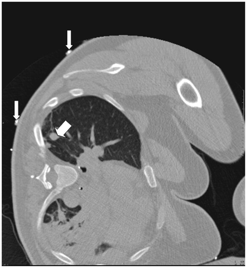
A. Close-up view of the tracking apparatus. Passive fiducials (red arrow) and active fiducials (white arrow) are located within the acquisition area of the field generation (top left hand corner of the figure). These fiducials are used for registration of the tracking system with pre-procedural CT images. B. Planning CT scan illustrates a solitary 12 mm melanoma metastasis in the right lung (thick arrow). Fiducials (thin arrows) are used in the registration process.
Materials and Methods
An electromagnetic tracking system was used to guide RFA of a 12 mm right lung melanoma metastasis in a 56-year-old patient (Figure 1b). The patient opted for RFA over surgery due to potential morbidities in light of multiple previous surgeries, as well as the presence of slower growing extra-pulmonary metastases. The use of EMT was approved by the institutional investigational review board to assess the feasibility and accuracy of this technology. The patient gave written informed consent. The system consisted of a field generator (Figure 1a), a control unit and a sensor device (Aurora, Northern Digital Inc., Waterloo, ON), interfaced with registration and display custom software (Philips Research, Briarcliff, NY), and a commercially available tracked 22G stylet inside a standard 19G outer biopsy guider needle (Philips Healthcare, Toronto, ON). The patient was first anaesthetized, intubated and ventilated. Five adhesive active fiducial markers with 2 embedded 5 degree of freedom (DOF) tracking sensors per fiducial were placed near the expected skin entry point (figure 1a). The tracking coordinates of these sensors, which are necessary for the registration process, are obtained automatically during interruption of ventilation. Moreover, these sensors facilitate dynamic motion compensation during breathing. Seven passive conical fiducial markers (Pinpoint, Beekley, Bristol, Conn) were also placed as a backup method of manual registration, which was performed by placing the tracked needle sequentially in each sterile cone, a process that takes, on average, 35 seconds [4], and that can be carried out automatically by skin patches, as well. A planning CT scan (3mm thick sections, 1.5mm overlap, 16-slice CT MX 8000, Philips Medical Systems, Cleveland, OH) was obtained during interruption of ventilation. With use of custom software on the workstation, the skin fiducials were identified manually on the CT scan (Figure 1b). The skin entry site was estimated using a radio-opaque grid (E-Z-EM Inc., Lake Success, NY).
Both conventional techniques and tracking-assisted techniques were used sequentially to estimate needle angulations. The conventional technique involved using the most recent axial CT image of the target and the skin entry point, as determined from the CT skin grid. The 19G guider needle was placed 5mm below the skin surface by an interventional radiologist experienced in RFA. Then the appropriate angle for straight needle advancement was produced through freehand manipulation of the needle. In the usual conventional fashion, once it was felt that the appropriate needle trajectory had been achieved, the virtual position of the needle and expected straight line trajectory were captured using tracking software (Figure 2). Ventilation was interrupted during trajectory tracking. The operator was blinded to the tracking display throughout this manual process.
Fig. 2.
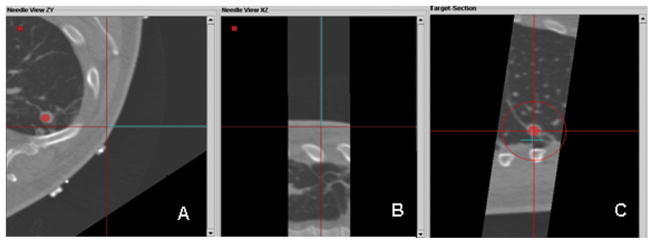
Custom tracking software displays multiplanar views during conventional freehand attempt toline up needle with lesion; operator is blinded to tracking display at this moment. Display of the virtual guider needle (blue line) shows the planned trajectory toward the target (red circle); this is updated in real-time. A. Axial plane shows needle off target B. Para-coronal image that includes the virtual needle does not include the red dot representing the target, illustrating that the lesion and the needle path are not in the same plane. C. “View down the needle shaft”, (or “bird’s eye view”) shows the needle tip (blue “+”) is not in line with the target lesion (red dot). (The red circle gets smaller the closer the needle tip gets to the plane of the target, during insertion, signifying distance to target or target plane.)
To assess and compare the accuracy of EMT guidance, the physician was then unblinded and the tracking-assisted approach was attempted. The 19G guider needle was removed and reinserted by using tracking software guidance only. Through real-time updated display of the virtual needle position, and by assuming a straight insertion, the operator aligned the guider needle with the tracked target center (Figure 3). Once a satisfactory needle trajectory was achieved, a CT scan of the tracked guider needle in the chest wall was performed. To estimate the accuracy of tracking, the virtual position was retrospectively compared to this actual CT position (Figure 4). A single 3cm 17.5G impedance-controlled active-tip Cooltip RFA electrode (Valley Lab, Covidien, Boulder, CO) was then placed immediately adjacent to the guider needle (tandem technique), and inserted in a single motion into the lung and tumor (Figure 5a). CT confirmation of RFA needle position was performed at 3mm collimation with 50% overlap. RFA of the tumor followed for 12 minutes, using a sequential increasing current ramping algorithm with 5W power increments delivered. A CT scan taken immediately following the ablation illustrated a hazy density surrounding the original location of the tumor (Figure 5b). A review CT scan taken 22 months post-RFA shows a stable scar and complete treatment (Figure 5c).
Fig. 3.
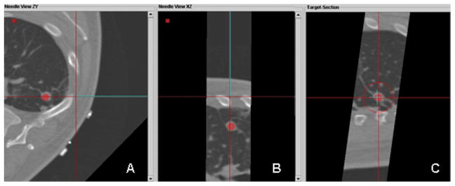
Custom tracking software displaying multiplanar views during tracked guider needle placement; operator is now viewing (not blinded to) the real-time tracking display. A. An axial plane shows the virtual needle (blue line) has a straight trajectory to the lesion. B. Para-coronal plan in the in the same plane as the needle, illustrates that the lesion and the needle path are in the same plane. C. “View down the needle shaft” shows that the needle tip (blue “+”) is directly in line with the target lesion (red dot).
Fig. 4.
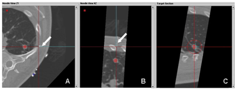
A, B, C. Retrospective post-processing overlay of confirmation CT (real needle) and expected or tracked position (virtual needle). The multiplanar images illustrate that the virtual needle (blue line) correlates well with the actual high attenuation needle (arrow pointing to underlying white line).
Fig. 5.
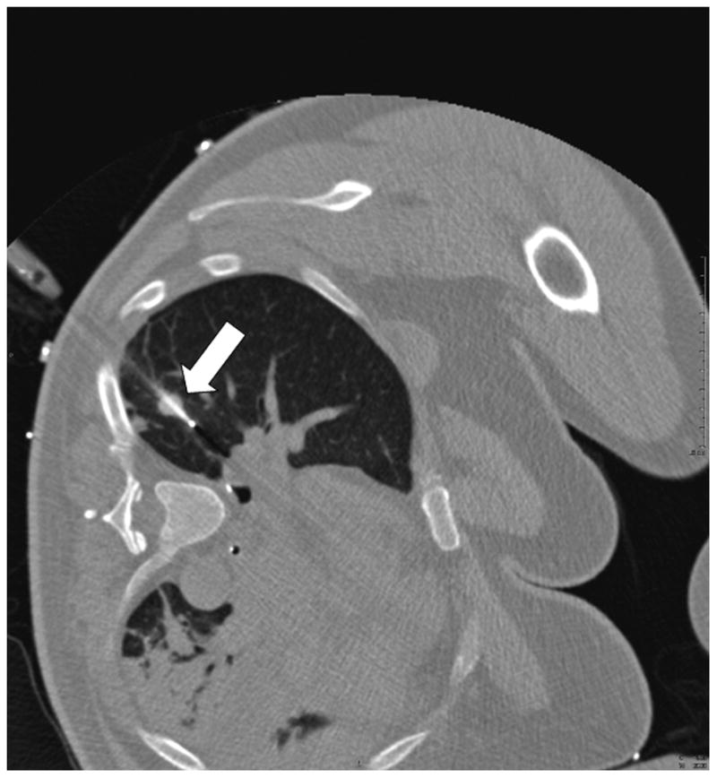
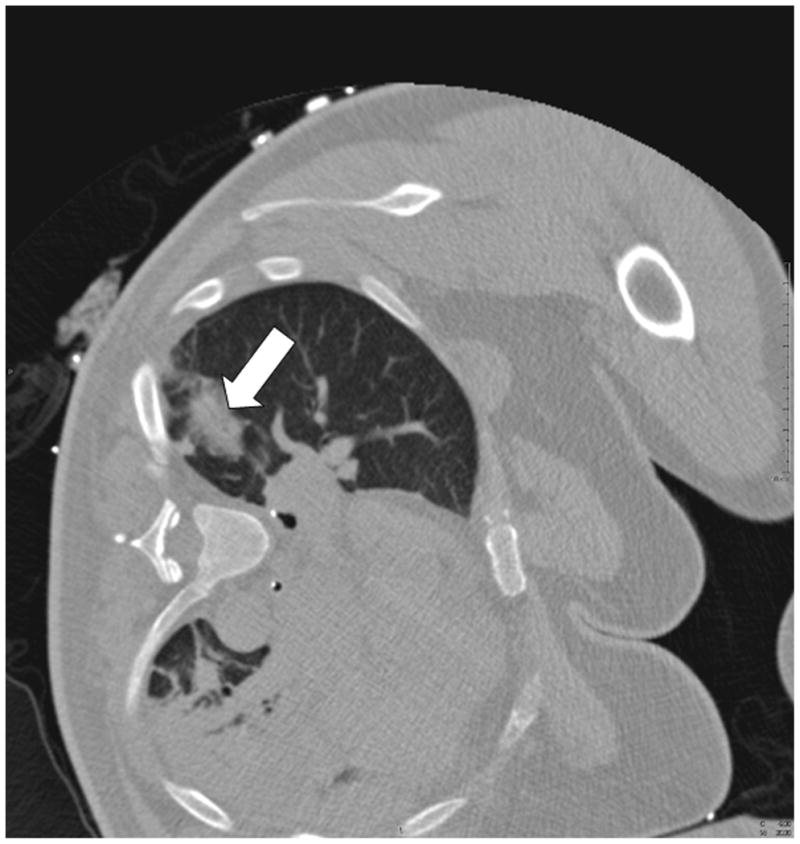
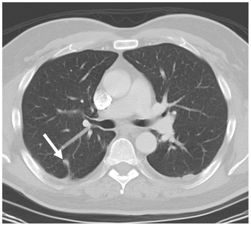
A. CT pre-ablation demonstrates adequate RFA electrode (arrow) through tumor. B. Post-procedural CT demonstrates characteristic ground-glass opacity in the location of the tumor. C. CT scan 22 months post-RFA shows stable scar and complete treatment.
Analysis
Following the procedure, the final virtual needle position was compared with the actual needle position on the post-insertion CT scan to assess the accuracy of the electromagnetic tracking system. There was near perfect alignment of the virtual and actual guider needles on the post-insertion CT (Figure 4). The overall accuracy of electromagnetic tracking-guided RFA can be quantitatively represented by the tracking error (target to registration error), which is the difference between the actual and the virtual (electromagnetic tracking -derived) needle tip positions. This error was 3.9 mm.
We then compared the relative accuracy of conventional and tracking-assisted approaches by assessing how near the trajectories passed relative to the center of the tumor. Figure 2 demonstrates that the conventional technique of freehand positioning of the needle for insertion would have resulted in significant needle misalignment with the tumor in two orthogonal planes, had the procedure occurred in conventional fashion, perhaps even requiring further needle repositioning. With tracking-assisted navigation (Figure 3), the operator viewed the trajectory of the needle in three planes and accurately targeted the tumor in a single insertion along the intended trajectory.
Discussion
The lung is an ideal tissue for RFA, because the inherent airspace outside the tumor provides an insulating effect for the thermal energy produced during the procedure, which may help concentrate heat and energy in the tumor [1, 2]. Numerous clinical trials on lung tumor RFA have been reported [2]. Indications for RFA in the lung are often based upon the size of the tumor as well as the staging characteristics. RFA may eradicate locally confined disease and local, short term control is high in tumors less than 3cm in diameter, and in favorable locations [1]. Tumors greater than 3cm in diameter may require overlapping ablations.
The electromagnetic tracking system was successfully used in prospectively guiding needle insertion in a patient without the use of regular imaging input. Assuming a straight trajectory, tracking-assisted needle insertion targeted the tumor more accurately than conventional freehand methods would have done in this patient. This could be due to 3D multi-planar reconstruction and real-time feedback. Multi-planar reconstructions are produced easily by rotating the plane around the needle, allowing the operator to appreciate needle trajectory in 3D, and view the target and any other critical structures in 3D. In addition, multi-planar reconstruction allows the operator to perform pre-procedural path planning. This is an advantage that can be particularly help fulin complex needle insertions that require steeper angles of approach, where it may be difficult to keep the needle in the same image plane as the target [5]. Meanwhile, real-time feedback of needle position relative to the ideal trajectory improves the operator’s ability to accurately redirect the needle as planned. Earlier feasibility studies of this system on both phantom and swine models have shown a statistically significant reduction of both the number of required needle passes and the overall radiation exposure [5].
The 3.9 mm tracking error quantifies the accuracy of electromagnetic tracking alone by measuring the distance between the virtual and actual positions of the guider needle tip in three different planes (Figure 4). It is within acceptable limits for clinical utility, and correlates well with a tracking error of 3.6–5.8mm from the larger retrospective series [4]. Causes for this error include inherent inaccuracy of the registration process (e.g. the non-uniform spatial accuracy of tracking within the magnetic field, interference from nearby metal structures), as well as intra-procedural causes such as respiratory motion, or patient or organ shift [3, 4,6,7]. It is unknown at this time whether this error could increase with more central location.
Electromagnetic tracking is a robust and relatively inexpensive and accurate technology that is widely used in non-medical fields. It is a potentially useful tool that has yet to be fully applied to interventional radiological and percutaneous procedures. Miniaturization of sensor coils has allowed the tracking of instruments asfine as 22G needles and 0.018 inch guide wires required for interventional radiology [3]. Future research is required to enhance respiratory motion modeling, reduce susceptibility to metal interference, and develop deformable modeling algorithms to better predict organ shift. Also, real-time mapping and feedback of overlapping ablation zones could reduce treatment gaps when treating larger tumors [4, 7, 8]. Although speculative, electromagnetic tracking could potentially improve clinical outcomes by reducing the number of confirmation CTs to monitor needle progression or minimizing the number of needle insertions.
Acknowledgments
This work was supported in part by the Center for Interventional Oncology & the Intramural Research Program of the National Institutes of Health. NIH & Philips Healthcare have a Cooperative Research and Development Agreement.
Footnotes
Financial disclosure statement: BJW and NIH have intellectual property in the field. This work was supported by the Center for Interventional Oncology & the Intramural Research Program of the National Institutes of Health Clinical Center.
References
- 1.Rose SC, Thistlethwaite PA, Sewell PE, et al. Lung cancer and radiofrequency ablation. J Vasc Interv Radiol. 2006;17:927–951. doi: 10.1097/01.RVI.0000222707.44902.66. [DOI] [PubMed] [Google Scholar]
- 2.Zhu JC, Yan TD, Morris DL. Systematic Review of Radiofrequency Ablation for Lung Tumors. Ann Surg Oncol. 2008;15(6):1765–1774. doi: 10.1245/s10434-008-9848-7. [DOI] [PubMed] [Google Scholar]
- 3.Wood BJ, Zhang H, Durrani A, et al. Navigation with Electromagnetic Tracking for Interventional Radiology Procedures: A Feasibility Study. J Vasc Interv Radiol. 2005;16:493–505. doi: 10.1097/01.RVI.0000148827.62296.B4. [DOI] [PMC free article] [PubMed] [Google Scholar]
- 4.Krücker J, Xu S, Glossop N, et al. Electromagnetic tracking for thermal ablation and biopsy guidance: clinical evaluation of spatial accuracy. J Vasc Interv Radiol. 2007;18(9):1141–1150. doi: 10.1016/j.jvir.2007.06.014. [DOI] [PMC free article] [PubMed] [Google Scholar]
- 5.Banovac F, Wilson E, Zhang H, et al. Needle biopsy of anatomically unfavorable liver lesions with an electromagnetic navigation assist device in a computed tomography environment. J Vasc Interv Radiol. 2006;17(10):1671–1675. doi: 10.1097/01.RVI.0000236589.74137.F6. [DOI] [PubMed] [Google Scholar]
- 6.Frantz DD, Wiles AD, Leis SE, et al. Accuracy assessment protocols for electromagnetic tracking systems. Phys Med Biol. 2003;48(14):2241–2251. doi: 10.1088/0031-9155/48/14/314. [DOI] [PubMed] [Google Scholar]
- 7.Borgert J, Kruger S, Timinger H, et al. Respiratory motion compensation with tracked internal and external sensors during CT-guided procedures. Computer Aided Surgery. 2006;11(3):119–125. doi: 10.1080/10929080600740871. [DOI] [PMC free article] [PubMed] [Google Scholar]
- 8.Wood BJ, Locklin JK, Viswanathan A, et al. Technologies for guidance of radiofrequency ablation in the multimodality interventional suite of the future. J Vasc Interv Radiol. 2007;18:9–24. doi: 10.1016/j.jvir.2006.10.013. [DOI] [PMC free article] [PubMed] [Google Scholar]


