Abstract
Core-shell, nanosized LiFePO4-carbon particles were made in one step by scalable flame aerosol technology at 7 g/h. Core LiFePO4 particles were made in an enclosed flame spray pyrolysis (FSP) unit and were coated in-situ downstream by auto thermal carbonization (pyrolysis) of swirl-fed C2H2 in an O2-controlled atmosphere. The formation of acetylene carbon black (ACB) shell was investigated as a function of the process fuel-oxidant equivalence ratio (EQR). The core-shell morphology was obtained at slightly fuel-rich conditions (1.0 < EQR < 1.07) whereas segregated ACB and LiFePO4 particles were formed at fuel-lean conditions (0.8 < EQR < 1). Post-annealing of core-shell particles in reducing environment (5 vol% H2 in argon) at 700 °C for up to 4 hours established phase pure, monocrystalline LiFePO4 with a crystal size of 65 nm and 30 wt% ACB content. Uncoated LiFePO4 or segregated LiFePO4-ACB grew to 250 nm at these conditions. Annealing at 800 °C induced carbothermal reduction of LiFePO4 to Fe2P by ACB shell consumption that resulted in cavities between carbon shell and core LiFePO4 and even slight LiFePO4 crystal growth but better electrochemical performance. The present carbon-coated LiFePO4 showed superior cycle stability and higher rate capability than the benchmark, commercially available LiFePO4.
Keywords: Lithium iron phosphate, coating, acetylene black, cathode material, lithium-ion battery
1. Introduction
The olivine LiFePO4 is attractive for high volume Li-ion battery applications (e. g., in hybrid or solely electric vehicles) (Padhi et al., 1997) as it is made from low cost raw materials, shows high cycle stability, is environmentally benign (Hong et al., 2009). Limitations of LiFePO4 are its low electric conductivity and slow Li-ion diffusion along the one-dimensional channels of its olivine structure (Morgan et al., 2004). The diffusion limitation can be addressed with smaller particles allowing higher charge- and discharge rates. The conductivity can be increased by Nb doping (Chung & Chiang, 2003), or embedding LiFePO4 in a conductive matrix (Chen & Dahn, 2002). Carbon black containing materials have typically 10-100 times higher electrical conductivity than doped LiFePO4 (Delacourt et al., 2006b). As dispersion of the conductive additive is particularly important for nano-sized particles (Patey et al., 2009b), a core-shell structure with active material as core and conductive coating as shell is ideal for assembling conductive nanostructures (Liu et al., 2006). For example, core-shell particles can minimize cell polarization as each particle receives electrons from all possible directions (Wang et al., 2008). Furthermore, the carbon shell can protect the core particle from reactions with the electrolyte as well as during its handling or processing.
Two main strategies to produce carbon-coated battery electrode materials are reported: (1) Admixing of (prefabricated) conductive carbon black during or after synthesis of the active material followed by intimate mixing/milling and high temperature annealing (Shin et al., 2006). The carbon black layer around LiFePO4 formed by this route is typically rough and discontinuous (Shin et al., 2006). (2) Co-synthesis of active material and carbon black to facilitate excellent dispersion at the nanoscale. This excellent dispersion has been achieved by flame aerosol technology (Spicer et al., 1998) that is able to produce active materials (LiMn2O4, Li4Ti5O12, LiFe5O8) for batteries (Ernst et al., 2007). This technology is quite attractive for its capacity to manufacture nanostructured ceramic materials at large scale, a key feature for reduction of the high cost of battery materials today (Masquelier, 2010). Furthermore, FSP can control product characteristics like size and crystallinity by varying precursor and oxidant composition and flow rate (Strobel & Pratsinis, 2007). Mixed acetylene carbon black (ACB) and LiMn2O4 have been made sequentially by separate open flames and the resulting, well-dispersed conductive ACB significantly improved the rate performance of nano-LiMn2O4 (Patey et al., 2009a). Core-shell particles are an alternative structure promising even better contact between active material and carbon black.
Here ACB-coated LiFePO4 particles with core-shell morphology are made continuously, for the first time to our knowledge, by flame aerosol technology, capable to produce, at least, up to 700 g/h of ACB-coated ceramic nanoparticles (Kammler et al., 2001). The influence of O2-stoichiometry, LiFePO4-ACB morphology, and annealing on the core-shell morphology and LiFePO4 crystallinity was investigated. The electrochemical performance (cycle stability & discharge rate capacity) of these core-shell LiFePO4-ACB particles is presented and compared to that of commercial LiFePO4 particles dispersed in carbon black.
2. Experimental
2.1 Apparatus
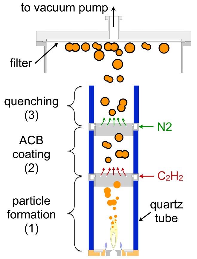
The in-situ ACB coating setup was developed and synthesis parameters were optimized based on flame aerosol synthesis and in-situ coating of particles (Ernst et al., 2008; Patey et al., 2009a; Teleki et al., 2008). Fig. 1 shows a schematic of the experimental setup for synthesis of core-shell LiFePO4-ACB particles. To prevent air entrainment, the flame reactor is enclosed by quartz glass tubes of 5.2 cm outer diameter and 0.25 cm wall thickness. The combustion environment can therefore be controlled precisely (Heine & Pratsinis, 2005). At 40 and 55 cm above the burner, gaseous C2H2 and N2, respectively, are injected into the gas stream dividing the reactor in 3 zones: (1) An O2-rich core particle formation zone, (2) an O2-lean C2H2-pyrolysis and carbon-coating zone, and (3) in a quenching and cooling zone.
Fig. 1.
Schematic of the enclosed FSP setup with a particle formation zone (1), an ACB-coating (2), and a quenching (3) zone. By enclosing the unit with quartz tubes, the O2 stoichiometry in the ACB-coating zone can be controlled precisely. The coated particles are cooled with N2 at the end of the coating zone to avoid carbon black combustion after contacting ambient air on the way to filtration.
In the lowest zone 1, core LiFePO4 particles are formed (details in section 2.2). A mixture of O2 and N2 (Pan Gas, ≥ 99.95) was fed as sheath gas with a constant flow rate of 19 L/min through 12 circular openings of 0.1 cm diameter surrounding the FSP burner at a radius of 2.2 cm from the nozzle center. The mixing ratio of N2 and O2 in this sheath gas was used to control the global equivalence ratio (EQR) in the reactor (Turns, 1996):
| (1) |
with nfuel and noxidant being the number of moles of fuel (LiFePO4 precursor solution, CH4 and C2H2) and oxidant (O2), respectively. The ratio in the numerator (real) represents the actual moles fed into the system, whereas the ratio in the denominator (stoichiometric) represents the moles needed theoretically for stoichiometric combustion of the above fuel to CO2 and H2O. All combustibles (LiFePO4 precursor solution, CH4 and C2H2) were regarded as fuel and the sum of all supplied O2 as oxidant.
At the beginning of zone 2 (at 40 cm above the FSP burner), 1 L/min C2H2 (Pan Gas, ≥ 99.5 %) was introduced through a stainless steel torus ring. For better gas mixing, a swirl motion is introduced by the radial alignment of the 12 equidistant circular outlets (0.05 cm in diameter) of the ring (Teleki et al., 2009). The aerosol of freshly-made LiFePO4 particles then passes through the coating section (zone 2) of 15 cm length before it is cooled with N2 from about 600 to below 300 °C in zone 3 to prevent oxidation of ACB in ambient air. This cooling is achieved by swirl-injection of 20 L/min N2 through a second torus ring at the entrance of zone 3. A third glass tube, 10 cm long, on top of that torus ring ensured mixing of N2 and product LiFePO4-ACB aerosol before its release to ambient air and particle collection on a glass-fiber filter (Whatman GF6, 25.7 cm in diameter) with the aid of a vacuum pump (Busch, Seco SV 1040C).
2.2 Particle Synthesis and Characterization
Core LiFePO4 nano-particles were made by FSP (Madler et al., 2002). Li-acetylacetonate (Sigma-Aldrich, 97 %), iron (III)-acetylacetonate (Fluka, ≥ 99 %) and tributyl phosphate (Fluka, ≥ 99 %) were mixed stoichiometrically (mol ratio Li/Fe/P = 1/1/1) and were dissolved in an equivolumetic mixture of 2-ethylhexanoic acid (Riedel-de Haën, ≥ 99 %), toluene (Riedel-de Haën), diethylene glycol monobutyl ether (Fluka, purum ≥ 98 %) and ethanol (Alcosuisse, 98 %) resulting in a precursor solution of 0.24 M (total metal concentration). That solution was fed through the FSP nozzle at 3 mL/min and dispersed by 3 L/min of O2 (Pan Gas, > 99.95 %) whereas 1.6 bar pressure drop was maintained over that nozzle. The spray was ignited by a support premixed flame of 2.5 L/min O2 and 1.25 L/min CH4 (Pan Gas, ≥ 99.5 %) through an annulus surrounding the dispersion O2 outlet (Madler et al., 2002).
Pure LiFePO4 was made in the same setup as with core-shell particles with EQR = 0.8 and 0.98 but without C2H2 flow. Pure ACB was made by spraying the above solvent solution without the Li, Fe, and P precursors. Co-synthesized ACB and LiFePO4 was made with two flames as described earlier (Patey et al., 2009a) using the above precursor solution.
Powder annealing was carried out in a thermo balance (Mettler-Toledo, TGA/SDTA851e) using 900 μL alumina crucibles 2/3 filled with slightly compressed (~20 kPa) sample material. Heating and cooling rates were both set to 10 °C/min. The annealing time is defined as the isothermal time of the run. Annealing was carried out by supplying 200 mL/min of 5 vol% H2 in argon (Hydrargon 5, Pan Gas). Low-temperature oxidation of in-situ ACB-coated LiFePO4 was made in a muffle oven (Barnstead International, Thermolyne 48000) at 420 °C in open ceramic crucibles and still air atmosphere. Heating and cooling rates were set to 10 °C/min and the oxidation time is defined as the isothermal time of the run.
Powders were characterized by N2 adsorption (specific surface area, SSA), X-ray diffraction (XRD) and transmission electron microscopy (TEM) For the calculation of the Brunauer–Emmett–Teller equivalent diameter (dBET) of pure LiFePO4 particles a LiFePO4 density of 3.577 g/cm3 was used (Zane et al., 2004). The ACB content (XACB) was determined thermogravimetrically (Mettler Toledo TGA/SDTA851e) by heating the as-prepared sample in a 70 μL alumina crucibles in O2 to 800 °C with 10 °C/min. The XACB was defined as the relative weight loss between 120 and 800 °C, as below 120 °C typically physically bound water is desorbed (Mueller et al., 2003). Particle size distributions (PSD) and their average diameter and geometric standard deviation were obtained by manually counting TEM particle images (Hinds, 1999).
2.3 Electrochemical Characterization
Dry powder of annealed core-shell LiFePO4-ACB made at EQR = 1.02 was used as active material. This material showed the most promising coating uniformity and thickness by TEM and was therefore used for all electrochemical evaluations. For slightly rougher coatings (e.g. EQR 1.07) one expects similar annealing as the also continuous but rougher ACB shell hinders particle sintering. Regarding electrochemical properties, rougher coatings are undesired, as they decrease the specific charge of the electrode by adding inactive mass and might even represent an additional Li+ diffusion resistance by the protruding asperities (contact resistance).
Commercial LiFePO4 (Sigma-Aldrich, LiFePO4, SSA = 14.5 m2/g, battery grade) with dBET = 116 nm and dXRD = 150 nm served as benchmark material and was processed into composite electrodes in the exact same way as the core-shell LiFePO4-ACB. The commercial material serves here as a common reference since the electrode preparation technique has great impact on the electrochemical performance (Marks et al., 2011). Carbon black (CB; Super P, TIMCAL SA, SSA = 62 m2/g) was used as an electrically conductive additive. Polyvinylidene fluoride (PVDF SOLEF 1015, Solvay) dissolved in N-methylpyrrolidinone (NMP, Fluka) was used as a binder. The mass-ratio (after drying) of AM/CB/PVDF in the electrodes was 83/8.5/8.5. To prepare the suspensions, all electrode constituents were mixed in NMP with an ultrasonic stirrer (Hielscher UP 200H) for 2 min at 200 W and 24 kHz. To prepare test electrodes, all suspensions were doctor-bladed at a “wet” thickness of 250 μm onto a carbon-coated aluminum current collector (GAIA, Nordhausen) and dried at 110 °C for 10 min at atmospheric pressure and under vacuum overnight. Afterwards, disk electrodes with a diameter of 1.3 cm were punched out and dried under vacuum at 120 °C overnight. Coin-type test cells were assembled in an argon-filled glove box with contents of less than 1 ppm of O2, N2, and H2O. Lithium metal (99.9 %, Aldrich) served as both reference and counter electrode (anode). A fiberglass separator (1 mm thick) was soaked with 500 μl of electrolyte (1 M LiPF6 in ethylene carbonate (EC) / dimethyl carbonate (DMC), 1:1 by mass, Ferro). This electrolyte was mixed with a detergent (Triton X-209, 2 wt%, Sigma Aldrich) prior to soaking the separator.
All electrochemical measurements (cycling and power protocol) were performed at 25 (±0.1) °C and a constant specific current corresponding to 0.5C - 16C (1C = 170 mA/g of active material, LiFePO4). For the rate capability experiments, the electrodes were cycled galvanostatically between 2.0 and 4.5 V vs. Li/Li+ for varying specific currents proportionally to the LiFePO4 content. These experiments were performed after 50 standard cycles at 2C rate. To promote complete charge/discharge at the respective potential limits, a potentiostatic step was included until the specific current decreased to 34 mA/g. All results are the average of three tests. The capacity density was obtained from the specific charge (mAh/g active material, LiFePO4) and the composite electrode volume, calculated from electrode projected area and thickness, respectively. Capacity fading is defined as the loss of specific discharge capacity per cycle, relative to the initial discharge capacity.
3. Results and Discussion
3.1 LiFePO4-ACB Morphology
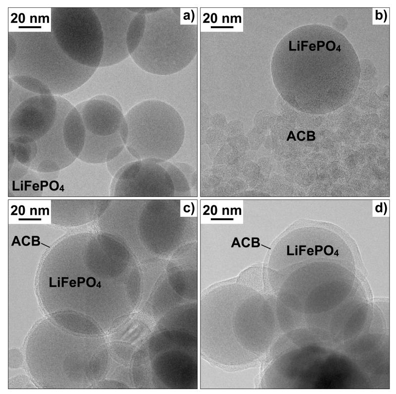
Fig. 2a shows a TEM picture of as-prepared, pure LiFePO4 particles. Fig. 2b,c,d show as-prepared powders made at EQR of 0.89, 1.02, and 1.07, respectively, by changing the O2-content in the sheath gas from 35 to 19 vol% at constant 1 L/min C2H2. It should be noted that other operation conditions, e.g. C2H2 injection height, injection rate, coating tube length also affected product particle characteristics (e.g. Teleki et al., 2008; 2009). The EQR, however, showed the strongest impact on ACB morphology (core-shell vs. segregated particles) and was therefore discussed preferentially here. The powders made at the above EQR contain 53, 18, and 10 wt% carbon black, respectively. As the particles in Fig. 2a do not contain visual carbon residues, the carbon black source in Fig 2b,c,d is the C2H2. Fig. 2b shows segregated single LiFePO4 particles and agglomerated ACB containing primary particles of approximately 10 nm diameter each despite excess of O2 in the overall system during synthesis. No coating is visible on the surface of LiFePO4 in Fig. 2a,b. In Fig. 2c, the core LiFePO4 particles are coated with a continuous and uniform 5 nm thick ACB layer. At higher EQR of 1.07 (Fig. 2d), the ACB layer thickness is slightly rougher with a tendency to form necks between the ACB-coated particles. The change from segregated to shell ACB morphology can be attributed to the different mode of carbon formation under fuel-rich and -lean conditions:
Fig. 2.
TEM images of as-prepared LiFePO4 and acetylene carbon black (ACB) nanoparticles: a) pure LiFePO4, b) segregated ACB and LiFePO4 made at EQR = 0.89. Core-shell LiFePO4-ACB made at EQR = c) 1.02 and d) 1.07.
No ACB coating was seen for C2H2-lean conditions (EQR < 1) as excess O2 is available. Iron oxides, however, are known to be good oxidation catalysts thus also LiFePO4 may rather oxidize C2H2 on its surface than allowing deposition of ACB. A similar effect was observed during FSP synthesis of carbon embedded Pt clusters where the presence of Pt reduced the carbon black yield by 80 % through catalytic burnoff (Ernst et al., 2008). For example, Fe2O3 utilizes surface O2 (available at EQR < 1) for the catalytic carbon black oxidation at 400 °C (Mul et al., 1998) as Fe2O3 can serve as an “O2-pump” (Reichert et al., 2010). Iron oxides are used also in diesel particle filters to oxidize soot particles (Wenger et al., 2008). Consequently, LiFePO4 particles do not behave like core SiO2 (Spicer et al., 1998) or TiO2 particles (Kammler & Pratsinis, 2003) that act as seeds facilitating surface growth of carbon black in atmospheric diffusion flames.
Additionally, at EQR < 1 the flame temperature is high by the exothermic oxidation of C2H2 favoring even more the catalytic activity of LiFePO4 for surface oxidation of ACB. As a result, mostly segregated ACB is formed at locally fuel-rich environments, preferentially without LiFePO4 contact.
For C2H2-rich conditions (EQR > 1), sticky, tar-like hydrocarbons were formed as indicated by a brownish precipitation on the backside of the glass fiber filters. Such products of incomplete combustion can easily bind on the LiFePO4 particle surface and therefore enhance formation of ACB coating shells (Fig. 2c,d). Furthermore, the oxidation activity of iron, in LiFePO4, is too low at fuel-rich conditions so hydrocarbons are available for ACB surface formation.
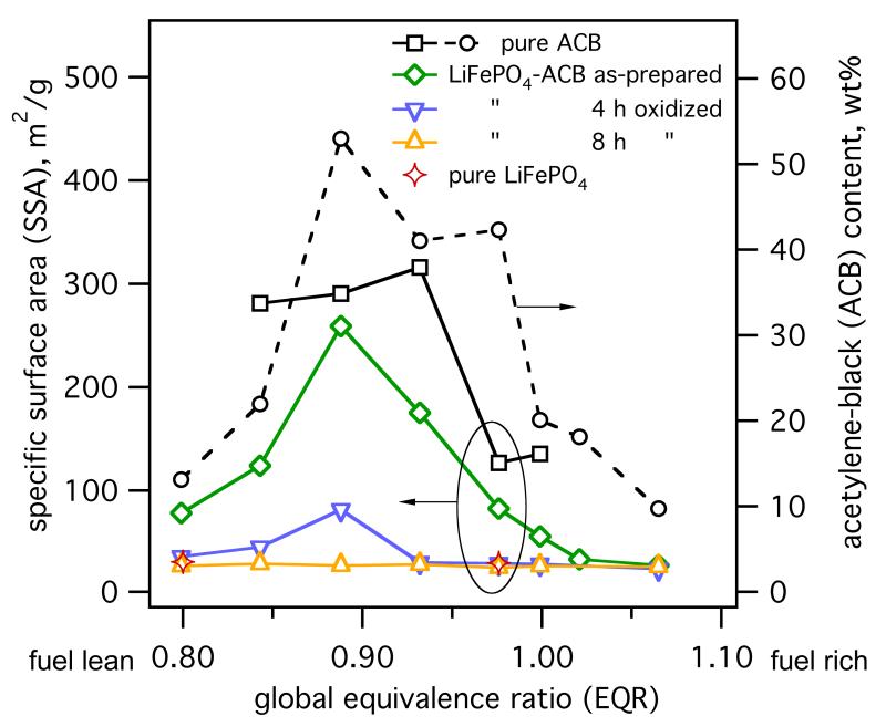
Fig. 3 shows the ACB content (XACB, circles) of the as-prepared powders as a function of EQR. All production parameters were kept constant (except O2 content in the sheath gas). For increasing EQR, the XACB increases, reaching a maximum at EQR = 0.9 and decreases thereafter. For EQR approaching 0.9, ACB is increasingly formed by C2H2-pyrolysis as less O2 is available for C2H2 combustion (consistent with the decreasing brightness of the flame). For higher EQR, XACB decreases as less C2H2 is combusted and pyrolyzed hence reducing the conversion of C2H2 to ACB. Core-shell coatings were made in red to bluish C2H2 flames (1.0 ≤ EQR ≤ 1.07) spread over the whole length of zone 2. For EQR > 1.1 the C2H2 coating flame extinguished, thus no ACB coating was formed anymore and the experiments were stopped for safety reasons.
Fig. 3.
ACB content (○) and SSA of as-prepared composite LiFePO4-ACB (◇), pure ACB (◻), and pure LiFePO4 (⟡) as well as the SSA of LiFePO4-ACB particles after 4 (▽) and 8 hours (△) oxidation in air at 420 °C as a function of the global EQR in the enclosed setup. Core-shell morphology is detected for (1.02 ≤ EQR ≤ 1.07) where the SSA of the composite LiFePO4-ACB material approaches that of pure LiFePO4 particles.
Fig. 3 shows also the SSA of as-prepared pure ACB (squares), LiFePO4 (stars) and LiFePO4-ACB (diamonds) particles. The SSA of pure LiFePO4 is constant, at about 30 m2/g, over the entire EQR range as here LiFePO4 particles (≈57 nm in diameter) are formed in zone 1 before being exposed to C2H2. Pure ACB always had much higher SSA than pure LiFePO4 in particular at fuel-lean conditions (≈ 300 m2/g) with a characteristic drop (≈ 150 m2/g) at fuel-rich EQR (Ernst et al., 2008).
The SSA of the as-prepared LiFePO4-ACB composite particles with mixed (Fig. 2b) or core-shell morphology (Fig. 2c,d), closely follows the evolution of XACB indicating that ACB determines the SSA variation. To elucidate this further, Fig. 3 shows also the SSA as function of EQR of LiFePO4-ACB, post-oxidized for 4 (inverse triangles) and 8 hours (triangles) in air at 420 °C. The SSA of composite particles gradually converges to that of pure LiFePO4 (stars) at all EQR (Fig. 3). After this 4-hour low temperature oxidation, powders made at 0.8 ≤ EQR ≤ 0.93 still contain residual carbon, as measured by Raman analysis (not shown). Increasing this oxidation time to 8 hours results in carbon free, amorphous LiFePO4 similar to as-prepared pure LiFePO4. The SSA of these low-temperature oxidized particles (≈ 30 m2/g) is the same as for pure LiFePO4 independently of EQR and initial carbon content in the composite. This is similar to flame-made ACB-coated SiO2 (Spicer et al., 1998) annealed in air to oxidize away their carbon layer and reveal the finer nanostructure of core SiO2. Clearly ACB formation does not influence the core-particle SSA as LiFePO4 formation is finished before ACB is coated as shell or formed as segregated particles.
3.2 Crystallinity & Annealing of Core-shell LiFePO4-ACB Particles
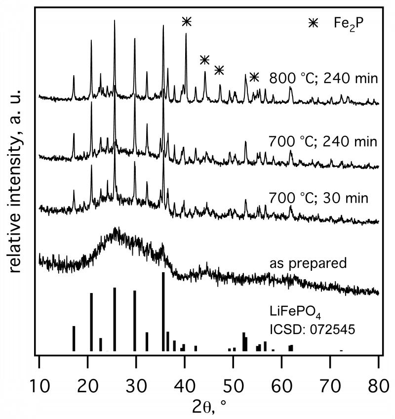
Fig. 4 shows XRD spectra of as-prepared ACB-coated LiFePO4 made at EQR = 1.02 (Fig. 2c) and after annealing in Ar/H2 at 700 & 800 °C for 30 - 240 minutes. As-prepared particles are amorphous by XRD though tiny spikes attributed to nanocrystalline LiFePO4 could be traced (e.g. at 25° & 35°). After 30 minutes at 700 °C distinctly crystalline LiFePO4 is formed. Extending the annealing time to 60 and 240 minutes improved the crystallinity, as seen by the reduction of the amorphous hump at 20° < 2θ < 40°. At 800 °C and 240 minutes the amorphous part (hump) disappeared totally, but Fe2P crystals were formed as ACB can reduce FePO4 to FeP2 (Herle et al., 2004). The presence of Fe2P, however, is not unwelcome here, in contrast to other crystalline phases, as it increases the electronic conductivity of the composite by several orders of magnitude by forming a grain-boundary nano-network of Fe2P and carbon with LiFePO4 (Herle et al., 2004).
Fig. 4.
As-prepared and annealed (Ar/H2 atmosphere) XRD spectra of core-shell LiFePO4-ACB (EQR = 1.02 ). Pure LiFePO4 phase was obtained at 700 °C, whereas up to 15 wt% Fe2P was formed at 800 °C.
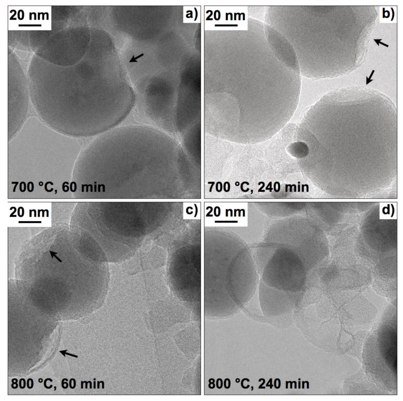
Fig. 5 shows the morphology of annealed ACB-coated LiFePO4 (EQR = 1.02). At 700 °C the ACB-shell remains mostly intact and attached to the core LiFePO4 particles, however, cavities start to form (arrows in Fig. 5a,b). At 800 °C, the core is progressively thinning out: cavities are formed already after 60 minutes (arrows in Fig. 5c) whereas after 240 minutes empty ACB shells and fragments are present (Fig. 5d). Most likely these cavities result from crystallization and subsequently from reduction of LiFePO4 to Fe2P and possibly to Li3PO4 or P (Yang et al., 2001). However, phosphorus (m/z = 31) was not detected by mass spectrometry of the effluent gas during TGA (not shown) but Fe2P formation is proven by post XRD analysis (Fig. 4). Similarly cavities between active material and CB were observed for CB-coated LiMnPO4 after annealing at 500 °C (Doan et al., 2010).
Fig. 5.
TEM images of core-shell LiFePO4-ACB (EQR = 1.02) after annealing in Ar/H2 at 700 °C for a) 60 and b) 240 min, as well as at 800 °C for c) 60 and d) 240 min. Morphology and size are generally preserved during annealing at 700 °C but at 800 °C the core LiFePO4 can disintegrate and may even breaks the ACB-shell. These particles may grow and form larger LiFePO4 crystals (according to XRD) leaving behind empty ACB shells.
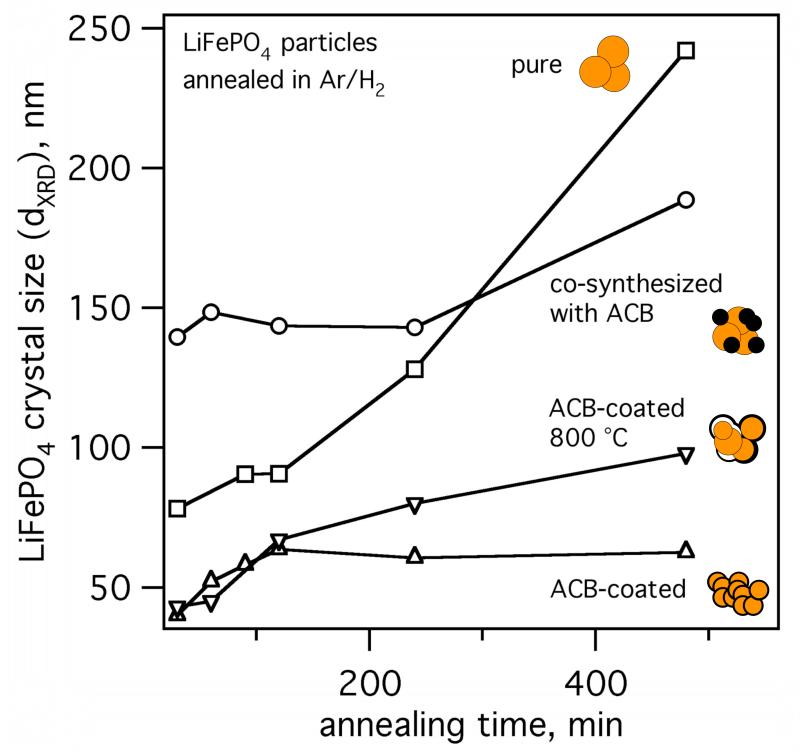
Fig. 6 shows the crystal size of FSP-made pure LiFePO4 (squares), ACB-coated (EQR = 1.02, triangles), and mixed LiFePO4 (circles) particles as a function of annealing time at 700 °C and ACB-coated LiFePO4 at 800 °C (EQR = 1.02, inverse triangles). Pure LiFePO4 particles (circles) shows substantial crystal growth from 80 - 250 nm as a function of annealing time at 700 °C. The mixed ACB-LiFePO4 particles grow from 140 to 180 nm indicating some hindering of crystal growth by the presence to ACB. The crystal size of ACB-coated LiFePO4, however, increases linearly during the first 120 minutes to 65 nm that is close to the BET-size of as-prepared, amorphous, pure LiFePO4 of 57 nm (Fig. 3) indicating formation of monocrystalline particles and consistent with the TEM images (Fig. 2 and 5). After 120 min the crystal size is constant for ACB-coated LiFePO4 at 700 °C. At 800 °C, crystal growth is initially similar to 700 °C but is increasing beyond 120 minutes. Perhaps carbothermal LiFePO4 decomposition to Fe2P (and possibly Li3PO4) steadily consumes the nanothin ACB-shells from the inside (Kadoma et al., 2010). Eventually, as the carbon shell vanishes, core LiFePO4 particles can meet and sinter to bigger crystals (according to XRD), leaving behind empty ACB-shells (Fig. 5d). Even though some coating-shells break open, crystal growth during annealing of carbon-coated LiFePO4 was effectively prevented compared to pure LiFePO4 (squares) or co-synthesized LiFePO4 with ACB (circles).
Fig. 6.
LiFePO4 crystal size evolution during annealing at 700 °C in Ar/H2 for particles with pure LiFePO4 (◻), co-synthesized LiFePO4-ACB (○), core-shell LiFePO4-ACB (△), and core-shell LiFePO4-ACB at 800 °C (▽). The crystal size of core-shell LiFePO4-ACB (EQR = 1.02) was preserved at 700 °C whereas at 800 °C the crystal size increased. Pure and co-synthesized LiFePO4-ACB (homogeneous mixture of amorphous LiFePO4 and ACB) showed substantial crystal growth during annealing at 700 °C.
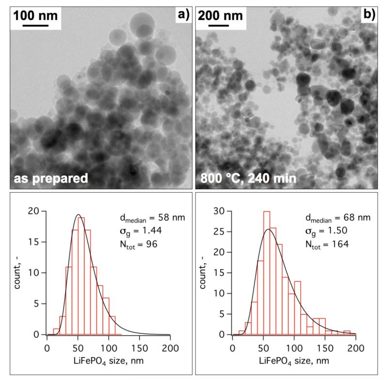
Fig. 7 shows TEM images and the corresponding size distributions of in-situ coated LiFePO4/ACB made at EQR = 1.02 in a) as-prepared and b) after annealing at 800 °C for 240 min. The as-prepared sample shows perfectly spherical particles with a count median diameter of 58 nm and a geometric standard deviation of 1.44. The latter nicely corresponds to that of the self-preserving particle size distribution for coagulation of spherical particles by Brownian motion in the continuum regime (Xiong & Pratsinis, 1991). The annealed sample, however, shows some regions with non-spherical, rather large particles most probably originating from sintering of primary particles after shell-breakup as shown in Fig. 5d. Nevertheless, the spherical shape of the as-prepared particles is mostly preserved during annealing. This favors the stacking and processing properties of the material (Liu et al., 2006). The size distribution of the annealed sample is also nearly lognormal with a slightly broader geometric standard deviation of 1.50 than the as-prepared sample. The volume based median diameter (88 nm) of the annealed sample, derived from the count median diameter (Hatch & Choate, 1929), compares well with the LiFePO4 crystal size (80 nm) by XRD (Fig. 6) underlining the formation of mostly monocrystalline LiFePO4 particles despite the appearance of the Fe2P phase.
Fig. 7.
Low magnification TEM images of a) as prepared b) and after annealing at 800 °C for 240 min core-shell LiFePO4-ACB (EQR = 1.02) with the corresponding counted particle size distributions.
3.3 Electrochemical Performance
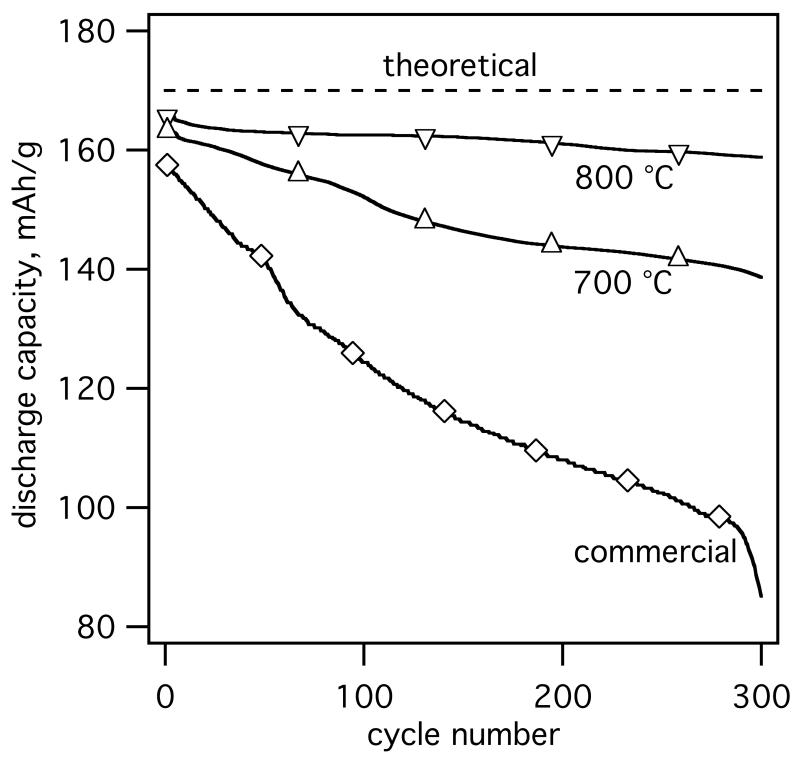
Fig. 8 shows representative electrochemical evaluation (cycling at 2C rate) of core-shell ACB-coated LiFePO4 (EQR = 1.02) annealed for 240 min at 700 °C and 800 °C in comparison to commercial LiFePO4 used as a benchmark. Commercial LiFePO4 shows capacity fading in the order of 0.2 % for the first 100 cycles decreasing to 0.08 % for the following cycles consistent with the literature (Bakenov et al., 2007). At the given experimental conditions the powder annealed at 800 °C shows higher practical specific discharge capacity than the 700 °C annealed and commercial powders. Perhaps the formation of Fe2P in the 800 °C annealed powder could have enhanced the electrical conductivity of the active material (Song et al., 2008) increasing the practical charge capacity of LiFePO4-ACB composite (please consider that the active mass was only corrected for the ACB content and not for the impurity phases). Both, 700 and 800 °C annealed core-shell LiFePO4-ACB powders show remarkable improvement in cycle stability with only 0.05 % and 0,01 % capacity fading per cycle, respectively. This could be attributed to lower polarization of the active material in the well-dispersed ACB matrix (Liu et al., 2008).
Fig. 8.
Galvanostatic discharge capacity per unit mass (specific charge) of core-shell LiFePO4-ACB annealed at 700 (△) and 800 °C (▽) as well as commercial LiFePO4 particles (◇) used for preparation of composite electrodes. Cycling was performed at 2.0–4.5 V (vs. Li/Li+) at 2C (1C =170 mA/g) and 25 °C.
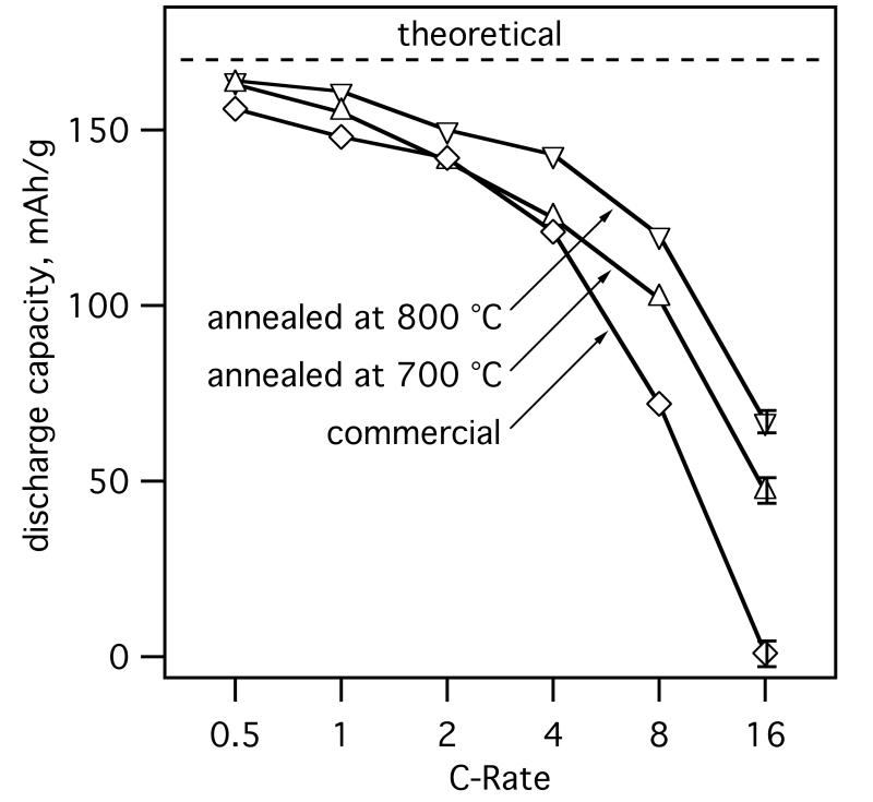
Fig. 9 shows the rate capability of the electrodes containing annealed core-shell LiFePO4-ACB and commercial LiFePO4 particles. Here the galvanostatic discharge capacity is shown for various C-Rates (0.5-16C) as an average over 10 cycles, starting from the 50th cycle under standard cycling. The in-situ ACB coated LiFePO4 shows high specific charge of 163 mAh/g for low C-rates (0.5C) corresponding to 96% of the theoretical charge capacity of LiFePO4 and the resulting capacity density is about 112 ± 4 mAh/cm3, well in line with commercial LiFePO4-based batteries. The improved conductivity and connectivity of the core-shell LiFePO4-ACB compared to benchmark LiFePO4 became significant at higher C-Rates whereas the 800 °C annealed particles performed best. A certain “size effect” due to smaller crystal sizes of core-shell LiFePO4-ACB compared to commercial LiFePO4 cannot be excluded (Delacourt et al., 2006a). Nevertheless, core-shell LiFePO4-ACB annealed at 800 °C (dXRD = 80 nm) shows better performance in cycle stability and rate capability than 700 °C (dXRD = 61 nm) annealed, despite 30% larger LiFePO4 crystal size. In literature, however, best results were obtained for moderate annealing temperatures of 550 °C (Yamada et al., 2001) or 700 °C (Mi et al., 2005) as above these the crystals were sintering decreasing the practical charge/discharge capacity of LiFePO4.
Fig. 9.
Galvanostatic discharge capacity per unit mass (specific charge) at various C-rates for core-shell LiFePO4-ACB annealed at 700 (△) and 800 °C (▽) as well as commercial LiFePO4 particles (◇) used for the preparation of composite electrodes. Electrochemical measurements were performed at 2.0– 4.5 V (vs. Li/Li+) at 25 °C. The constant current (galvanostatic) part of the total charge capacity at each C-rate is shown as the average of 10 cycles, after about 50 cycles at standard 2C rate. The indicated error bar at 16C represents the largest variation over all displayed C-rates.
Here, the core-shell morphology hindered LiFePO4 sintering enabling high temperature annealing with limited sintering and crystal growth. Better crystallinity in conjunction with small particles for high C-rates could therefore be made. The improved crystallinity in high temperature annealed particles reduces blockages in the one-dimensional Li-ion diffusion channels (Yang et al., 2001) and the presence of Fe2P increases the electrical conductivity of LiFePO4 (Song et al., 2008). The ACB shell prevented particle sintering completely up to 700 °C and significantly at 800 °C so particles with crystal sizes well below 100 nm were made showing that the present technology has potential for synthesis of cathode material contributing to durable high performance batteries.
4. Conclusions
Nano-scale LiFePO4 particles that are thinly (≈ 5 nm) coated with acetylene carbon black (ACB) were continuously produced (7 g/h) by a flame aerosol process. Core-shell morphologies were made at slightly fuel-rich conditions (1.02 ≤ EQR ≤ 1.07) while in excess O2, LiFePO4 efficiently catalyzed ACB oxidation on its surface, preventing its coating and forming segregated ACB. The ACB-shell did not influence the LiFePO4 core particle size as LiFePO4 formation is finished before synthesis and deposition of the ACB shell. ACB-coated particles were annealed at 700 °C in reducing Ar/H2 resulting in monocrystalline LiFePO4 particles with dXRD = 65 nm. Further particle growth was inhibited by the presence of the ACB shell on their surface. Annealing at 800 °C in Ar/H2 for 4 hours yielded up to 15 wt% Fe2P by carbothermal reduction of LiFePO4 through its ACB-shell that facilitated limited LiFePO4 crystal growth and cavities and even hollow carbon shells. Core-shell LiFePO4-ACB particles showed high reversible practical charge capacity of about 160 mAh/g, capacity density of about 112 mAh/cm3 and excellent cycling stability with less than 3 % capacity loss after 200 cycles at 2C.
Acknowledgements
We kindly acknowledge financial support of ETH Zürich (TH-09 06-2) and the European Research Council/European Community (under FP7). We thank Dr. Frank Krumeich (ETHZ) and the Electron Microscopy Center of ETH Zurich (EMEZ) for providing the necessary infrastructure for the TEM images.
References
- Bakenov Z, Nakayama M, Wakihara M. A nonflammable lithium polymer battery with high performance for elevated temperature applications. Electrochem. Solid State Lett. 2007;10:A208–A211. [Google Scholar]
- Chen ZH, Dahn JR. Reducing carbon in LiFePO4/C composite electrodes to maximize specific energy, volumetric energy, and tap density. J. Electrochem. Soc. 2002;149:A1184–A1189. [Google Scholar]
- Chung SY, Chiang YM. Microscale measurements of the electrical conductivity of doped LiFePO4. Electrochem. Solid-State Lett. 2003;6:A278–A281. [Google Scholar]
- Delacourt C, Poizot P, Levasseur S, Masquelier C. Size effects on carbon-free LiFePO4 powders. Electrochem. Solid State Lett. 2006a;9:A352–A355. [Google Scholar]
- Delacourt C, Wurm C, Laffont L, Leriche JB, Masquelier C. Electrochemical and electrical properties of Nb- and/or C-containing LiFePO4 composites. Solid State Ion. 2006b;177:333–341. [Google Scholar]
- Doan TNL, Bakenov Z, Taniguchi I. Preparation of carbon coated LiMnPO4 powders by a combination of spray pyrolysis with dry ball-milling followed by heat treatment. Adv. Powder Technol. 2010;21:187–196. [Google Scholar]
- Ernst FO, Buchel R, Strobel R, Pratsinis SE. One-step flame-synthesis of carbon-embedded and -supported platinum clusters. Chem. Mat. 2008;20:2117–2123. [Google Scholar]
- Ernst FO, Kammler HK, Roessler A, Pratsinis SE, Stark WJ, Ufheil J, Novák P. Electrochemically active flame-made nanosized spinels: LiMn2O4, Li4Ti5O12 and LiFe5O8. Mater. Chem. Phys. 2007;101:372–378. [Google Scholar]
- Hatch T, Choate SP. Statistical description of the size properties of non-uniform particulate substances’. J. Frankl. Inst. 1929;207:369–387. [Google Scholar]
- Heine MC, Pratsinis SE. Droplet and particle dynamics during flame spray synthesis of nanoparticles. Ind. Eng. Chem. Res. 2005;44:6222–6232. [Google Scholar]
- Herle PS, Ellis B, Coombs N, Nazar LF. Nano-network electronic conduction in iron and nickel olivine phosphates. Nat. Mater. 2004;3:147–152. doi: 10.1038/nmat1063. [DOI] [PubMed] [Google Scholar]
- Hinds WC. Aerosol technology : properties, behavior, and measurement of airborne particles. Wiley; New York: 1999. [Google Scholar]
- Hong J, Wang CS, Chen X, Upreti S, Whittingham MS. Vanadium modified LiFePO4 cathode for Li-ion batteries. Electrochem. Solid-State Lett. 2009;12:A33–A38. [Google Scholar]
- Kadoma Y, Kim JM, Abiko K, Ohtsuki K, Ui K, Kumagai N. Optimization of electrochemical properties of LiFePO4/C prepared by an aqueous solution method using sucrose. Electrochim. Acta. 2010;55:1034–1041. [Google Scholar]
- Kammler HK, Mueller R, Senn O, Pratsinis SE. Synthesis of silica-carbon particles in a turbulent H2-air flame aerosol reactor. AIChE J. 2001;47:1533–1543. [Google Scholar]
- Kammler HK, Pratsinis SE. Carbon-coated titania nanostructured particles: Continuous, one-step flame-synthesis. J. Mater. Res. 2003;18:2670–2676. [Google Scholar]
- Liu H, Fu LJ, Zhang HP, Gao J, Li C, Wu YP, Wu HQ. Effects of carbon coatings on nanocomposite electrodes for lithium-ion batteries. Electrochem. Solid State Lett. 2006;9:A529–A533. [Google Scholar]
- Liu YJ, Li XH, Guo HJ, Wang ZX, Peng WJ, Yang Y, Liang RF. Effect of carbon nanotube on the electrochemical performance of C-LiFePO4/graphite battery. J. Power Sources. 2008;184:522–526. [Google Scholar]
- Madler L, Stark WJ, Pratsinis SE. Flame-made ceria nanoparticles. J. Mater. Res. 2002;17:1356–1362. [Google Scholar]
- Marks T, Trussler S, Smith AJ, Xiong DJ, Dahn JR. A guide to Li-ion coin-cell electrode making for academic researchers. J. Electrochem. Soc. 2011;158:A51–A57. [Google Scholar]
- Masquelier C. Plenary Talk: The impact of downsizing LiFePO4 particles to nanoscale: a key step for new generations of Li-ion batteries. 2010 World Congress of Particle Technology for Students; TU Delft, Netherlands. 2010. [Google Scholar]
- Mi CH, Zhao XB, Cao GS, Tu JP. In situ synthesis and properties of carbon-coated LiFePO4 as Li-ion battery cathodes. J. Electrochem. Soc. 2005;152:A483–A487. [Google Scholar]
- Morgan D, Van der Ven A, Ceder G. Li conductivity in LixMPO4 (M = Mn, Fe, Co, Ni) olivine materials. Electrochem. Solid-State Lett. 2004;7:A30–A32. [Google Scholar]
- Mueller R, Kammler HK, Wegner K, Pratsinis SE. OH surface density of SiO2 and TiO2 by thermogravimetric analysis. Langmuir. 2003;19:160–165. [Google Scholar]
- Mul G, Kapteijn F, Doornkamp C, Moulijn JA. Transition metal oxide catalyzed carbon black oxidation: A study with O-18(2) J. Catal. 1998;179:258–266. [Google Scholar]
- Padhi AK, Nanjundaswamy KS, Goodenough JB. Phospho-olivines as positive-electrode materials for rechargeable lithium batteries. J. Electrochem. Soc. 1997;144:1188–1194. [Google Scholar]
- Patey TJ, Büchel R, Ng SH, Krumeich F, Pratsinis SE, Novák P. Flame co-synthesis of LiMn2O4 and carbon nanocomposites for high power batteries. J. Power Sources. 2009a;189:149–154. [Google Scholar]
- Patey TJ, Hintennach A, La Mantia F, Novák P. Electrode engineering of nanoparticles for lithium-ion batteries-Role of dispersion technique. J. Power Sources. 2009b;189:590–593. [Google Scholar]
- Reichert D, Bockhorn H, Kureti S. Recent advances in the understanding of the direct conversion of soot and NO on Fe2O3 catalyst in diesel exhaust. Chim. Oggi-Chem. Today. 2010;28:51–53. [Google Scholar]
- Shin HC, Cho WI, Jang H. Electrochemical properties of carbon-coated LiFePO4 cathode using graphite, carbon black, and acetylene black. Electrochim. Acta. 2006;52:1472–1476. [Google Scholar]
- Song MS, Kim DY, Kang YM, Kim YI, Lee JY, Kwon HS. Amphoteric effects of Fe2P on electrochemical performance of lithium iron phosphate-carbon composite synthesized by ball-milling and microwave heating. J. Power Sources. 2008;180:546–552. [Google Scholar]
- Spicer PT, Artelt C, Sanders S, Pratsinis SE. Flame synthesis of composite carbon black-fumed silica nanostructured particles. J. Aerosol. Sci. 1998;29:647–659. [Google Scholar]
- Strobel R, Pratsinis SE. Flame aerosol synthesis of smart nanostructured materials. J. Mater. Chem. 2007;17:4743–4756. [Google Scholar]
- Teleki A, Buesser B, Heine MC, Krumeich F, Akhtar MK, Pratsinis SE. Role of gas-aerosol mixing during in situ coating of flame-made titania particles. Ind. Eng. Chem. Res. 2009;48:85–92. [Google Scholar]
- Teleki A, Heine MC, Krumeich F, Akhtar MK, Pratsinis SE. In situ coating of flame-made TiO2 particles with nanothin SiO2 films. Langmuir. 2008;24:12553–12558. doi: 10.1021/la801630z. [DOI] [PubMed] [Google Scholar]
- Turns SA. An introduction to combustion; concepts and applications. McGraw-Hill; New York: 1996. [Google Scholar]
- Wang YG, Wang YR, Hosono EJ, Wang KX, Zhou HS. The design of a LiFePO4/carbon nanocomposite with a core-shell structure and its synthesis by an in situ polymerization restriction method. Angew. Chem.-Int. Edit. 2008;47:7461–7465. doi: 10.1002/anie.200802539. [DOI] [PubMed] [Google Scholar]
- Wenger D, Gerecke AC, Heeb NV, Naegeli H, Zenobi R. Catalytic diesel particulate filters reduce the in vitro estrogenic activity of diesel exhaust. Anal. Bioanal. Chem. 2008;390:2021–2029. doi: 10.1007/s00216-008-1872-8. [DOI] [PubMed] [Google Scholar]
- Xiong Y, Pratsinis SE. Gas-phase production of particles in reactive turbulent flows. J. Aerosol. Sci. 1991;22:637–655. [Google Scholar]
- Yamada A, Chung SC, Hinokuma K. Optimized LiFePO4 for lithium battery cathodes. J. Electrochem. Soc. 2001;148:A224–A229. [Google Scholar]
- Yang SF, Zavalij PY, Whittingham MS. Hydrothermal synthesis of lithium iron phosphate cathodes. Electrochem. Commun. 2001;3:505–508. [Google Scholar]
- Zane D, Carewska M, Scaccia S, Cardellini F, Prosini PP. Factor affecting rate performance of undoped LiFePO4. Electrochim. Acta. 2004;49:4259–4271. [Google Scholar]


