Abstract
Background
The proliferate nature of DNA microarray results have made it necessary to implement a uniform and quick quality control of experimental results to ensure the consistency of data across multiple experiments prior to actual data analysis.
Results
Array-A-Lizer is a small and convenient stand-alone tool providing the necessary initial analysis of hybridization quality of an unlimited number of microarray experiments. The experiments are analyzed for even hybridization across the slide and between fluorescent dyes in two-color experiments in spotted DNA microarrays.
Conclusions
Array-A-Lizer allows the expedient determination of the quality of multiple DNA microarray experiments allowing for a rapid initial screening of results before progressing to further data analysis. Array-A-Lizer is directed towards speed and ease-of-use allowing both the expert and non-expert microarray researcher to rapidly assess the quality of multiple microarray hybridizations. Array-A-Lizer is available from the Internet as both source code and as a binary installation package.
Background
The ongoing development of DNA microarray analysis equipment have diminished both the price and workload associated with microarray experiments leading to development of data at a tremendous rate. It is not unusual for a group of researchers to be able to produce and scan 50–100 microarray slides per week. The processing of such large amounts of experimental data, first requires verification of the overall quality of the experiments. Array-A-Lizer employs two tests to monitor the quality of the hybridization with respect to uniformity across the slide as well as relative intensity of the fluorescent dyes in two color experiments: 1) spectrum analysis of the signal across the microarray slide and 2) comparison of the two dyes that are used in two-color experiments (for instance Cy3 and Cy5).
Implementation
The Array-A-Lizer graphical user interface (GUI) is created in Borland Delphi and the statistical calculations are carried out in the R-project statistical scripting language [1]. Array-A-Lizer includes a microdistribution of the R-project and contains options for specifying the graphical output type as either bitmaps or postscript. Array-A-Lizer supports experiment files from GenePixPro and Spotfinder through an open architecture, which can be extended to include other file formats. Array-A-Lizer runs on the Microsoft Windows platform.
Results and discussion
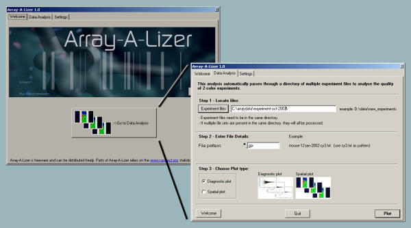
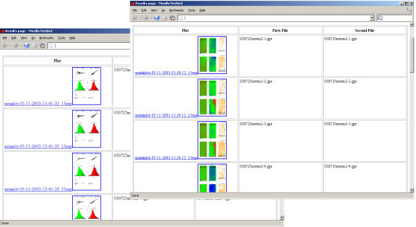
Array-A-Lizer is an application for rapid quality control of large DNA microarray experiments. The program consists of a collection of scripts, that are contained and accessed through a GUI to ease their use (figure 1). The main advantage of the program is the rapid processing of an unlimited number of experiments. Array-A-Lizer generates reports with a graphical analysis of each experiment, providing the researcher with a rapid survey of the quality of experiments (figures 2 and 3). Additionally, the program returns an overview of the results in the system browser with hyperlinks to each analysis report (figure 4).
Figure 1.

Graphical User Interface. An easily accessible graphical user interface is used to select experiments and analysis method.
Figure 2.

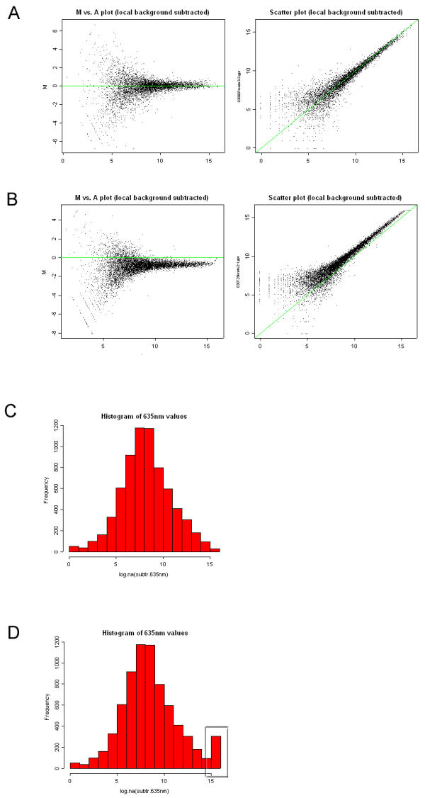
Diagnostic report. A + B) The diagnostic method generates scatter plots of the dual color hybridization data, both as MvA plots and red/green-scatter plots. In these plots the green line represents M = 0 and red = green respectively, making it easy to assess the balance between the green and the red channel. C + D) The distribution of log2 transformed intensities from the individual channels are visualized by plotting the data as histograms. Finally, the report contains information on the files used to generate the diagnostic plots, the number of saturated spots, and the number of negative spots (background is higher than foreground).
Figure 3.

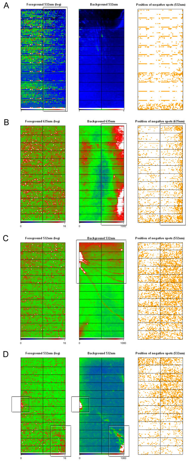
Spatial report. Output from the spatial analysis method shows various representations of analyzed data according to the location of the spot on the array. A pseudo color representation is used to display log2 transformed foreground intensities and raw backgroundintensities. A plot showing the location of the negative values across the array is also generated. The cutoff value for the background data plot can be set in the GUI prior to analysis. A) Spatial plot from a hybridization showing clear fading at the right part of the slide. B) High background values results in increased frequency of negative spots. C) Inadequate post-hybridization washing often results in distinct background patterns. D) Bleeding of signal from the actual spot into the background area results in regions of high background values that are also visible in the foreground plot.
Figure 4.

Analysis reports. For easy accessibility, reports of the quality analyses including thumbnail pictures are presented in a hyperlinked document in the default Internet browser.
Array-A-Lizer facilitates the generation of several plots that detail the quality of the experiments. Two different analysis modes can be chosen, resulting in either a set of diagnostic plots or a spatial representation of the data.
In comparison to existing analysis packages, Array-A-Lizer is both quick and easy to use. It is a stand-alone application that can be installed on any desktop computer running MS Windows. It is intended for easy visualization of microarray data allowing both the expert and non-expert microarray researcher to assess the quality of multiple microarray hybridizations.
Diagnostic report
In this mode, the experimental data are used to generate several diagnostic plots (figure 2) as well as statistics on the identified spots. The Array-A-Lizer diagnostic report includes both MvA plots (figure 2A left)[2] and red/green-scatter plots (figure 2A right), both of which show spot intensities after local background subtraction.
MvA plots display the log intensity ratio M = log2(R/G) versus the mean log intensity  . This plot type is widely use to visualize array data because it directly displays the red to green ratios, which are often the quantities of interest in most experiments. Furthermore, MvA plots make it easy to identify intensity dependent biases in the data (i.e. curvature or 'banana shape'). In scatter plots, the intensities from the green channel are plotted against the red channel after log2 transformation. Genes displaying difference in signal intensities in the two channels are plotted off the diagonal and genes showing similar intensities are plotted close to the the diagonal.
A common source of variation in microarray data acquisition is attributed by incorrectly balanced photomultiplier tube (PMT) settings during scanning. This results in overall differences in signal intensities obtained from either channel and a shift of the data from the x-axis (M = 0) or the diagonal (red = green) of the ideal MvA and scatter-plot respectively (figure 2B).
Finally, the diagnostic analysis generates histograms of the log2 transformed data for comparison of the distribution of intensities between the two channels. The histograms display the signal intensities across the slide (figure 2C). Overamplified channels (PMT levels are set too high) will result in many saturated spots, which is revealed as an over representation of high intensity values (figure 2D).
The diagnostic report includes information on which files were used for the analysis, the number of saturated spots, and the number of negative values, i.e. the number of spots where the background intensity was higher than the foreground intensity.
Spatial report
The spatial analysis results in a graphical representation of microarray data according to the location on the slide (figure 3). From each channel, three different plots are generated showing the log2 transformed foreground intensities, the background intensities, and a plot showing the location of negative values (background higher than foreground). This analysis method can be used to identify spatial effects on the hybridized arrays such as fading or illumination at the edges due to cover-slip effects (figure 3A and 3B) or scratches and artifacts resulting from inadequate washing of slides (figure 3C and 3D).
The cut-off values on the background plot can be set from the GUI prior to starting the analysis. Keeping these limits fixed will allow easy detection of pronounced fluctuations in background intensities both between and within slides.
Conclusion
With the reduced cost and labor of DNA microarray experiments, it is important that the inherent high through-put nature of the technology does not lower the quality of data and it is therefore vital that the control of experimental variability is consistently monitored, so the quality of subsequent data analysis is not severely weakened by the infusion of low quality data. Initial quality control is necessary and Array-A-Lizer delivers an easy-to-use application for rapid determination of experiment quality.
Availability and requirements
Project name: Array-A-Lizer
Project home page: http://www.bioinformatics.org/arrayalizer
Operating system: MS Windows
Programming language: Delphi and R
License: GNU GPL
Any restrictions to use by non-academics: None
List of Abbreviations
GNU: GNU's Not Unix
GPL: General public license
GUI: Graphical user interface
PMT: Photomultiplier tube
Authors' contributions
AP and MWM conceived of the project and contributed equally to the work presented in this manuscript. JF supervised the project and provided the funding. All authors read and approved the manuscript.
Contributor Information
Andreas Petri, Email: andp@novonordisk.com.
Jan Fleckner, Email: jafl@novonordisk.com.
Mads Wichmann Matthiessen, Email: bmc@madswichmann.dk.
References
- Ripley BD. The R project in statistical computing. MSOR Connections The newsletter of the LTSN Maths, Stats & OR Network. 2001;1:23–25. [Google Scholar]
- Yang HV, Dudoit S, Luu P, Lin DM, Peng V, Ngai J, Speed TP. Normalization for cdna microarray data: a robust composite method addressing single and multiple slide systematic variation. Nucl Acids Res. 2002;30:e15. doi: 10.1093/nar/30.4.e15. [DOI] [PMC free article] [PubMed] [Google Scholar]


