

Abstract
Present prosthetic heart valves, while hemodynamically effective, remain limited by progressive structural deterioration of tissue valves or the burden of chronic anticoagulation for mechanical valves. An idealized valve prosthesis would eliminate these limitations. Polymeric heart valves (PHVs), fabricated from advanced polymeric materials, offer the potential of durability and hemocompatibility. Unfortunately, the clinical realization of PHVs to date has been hampered by findings of in vivo calcification, degradation and thrombosis. Here, the authors review the evolution of PHVs, evaluate the state of the art of this technology and propose a pathway towards clinical reality. In particular, the authors discuss the development of a novel aortic PHV that may be deployed via transcatheter implantation, as well as its optimization via device thrombogenicity emulation.
Keywords: aortic stenosis, device thrombogenicity emulation, nano-composite, platelet activation, polyurethane, SIBS, transcatheter valve replacement
Prosthetic heart valves for aortic valve replacement
The American Heart Association estimates that 2% of the US population suffers from valvular heart disease (VHD), with 4% of individuals over the age of 65 years having clinical aortic stenosis (AS), largely due to calcification of the aortic valve (calcific aortic valve disease [CAVD]) [1]. With progression of stenosis, patients with CAVD typically become increasingly symptomatic, presenting with evident angina, syncope and heart failure. Patients with critical aortic valve area (AS <0.7 cm2) may be markedly symptomatic, with a severe reduction in their functional capacity, coupled with a dramatic increase in their near-term mortality rate [1]. Presently, approximately 40,000 patients undergo open surgical aortic valve replacement (AVR) per year in the USA [1].
The aortic valve (AV) has two basic failure modes, stenosis and insufficiency. Stenosis is a narrowing of the valve orifice, often with reduced leaflet excursion and opening restricting the outflow of blood from the left ventricle (LV), whereas insufficiency is incompetence or leakiness of the valve allowing regurgitation of blood following ventricular systole back into the LV. AS has several contributing etiologies including congenital defects, that is, bileaflet or quadrileaflet valves, calcification, commissural fusion and fibrosis [2]. AV insufficiency (AI) alone may be a result of rheumatic fever, with resultant rheumatic heart disease or aortic root dilatation, or other etiologies including infective endocarditis, calcific degeneration of the leaflets or presence of a bicuspid valve. Furthermore, patients may also present with a mixed form of VHD, that is, AS coupled with some degree of AI. Common parameters for diagnosing AV dysfunction are shown in Table 1. With both AS and AI the workload (W) on the heart increases, ultimately leading to heart failure. Cardiac work is calculated as W = ΔP × SV. Stenosis causes an increase in the transvalvular pressure gradient (ΔP) and an increase in after-load, resulting in an increase in ventricular wall tension and an increase in pressure-work for the heart. Insufficiency causes an increase in LV volume or preload, with progressive ventricular dilatation, an increase in stroke volume (SV) and increased overall volume-work for the heart. The ejection fraction (EF) of the heart is calculated as EF = SV/EDV, where EDV is the end diastolic volume. A healthy EF value is >55%, as the heart becomes weakened by increasing workloads the EF will drop. A combination of decreasing SV and increasing EDV as a result of AV disease leads to heart failure. Stenosis may result in hypertrophy of the ventricle, reducing its compliance, whereas regurgitation may result in progressive LV dilatation, stretching the ventricle beyond its elastic limits (Frank–Starling mechanism and Law of LaPlace), also reducing contractile force (inotropy) [3]. Both valvular derangements have the effect of reducing the EF. In selected cases, heart failure induced by AS may be reversed by valve replacement, if detected early.
Table 1.
American College of Cardiology American Heart Association Valvular Heart Disease classifications measured via echocardiography.
| Defect | Indicator | Mild | Moderate | Severe |
|---|---|---|---|---|
| AS | Jet velocity (m/s) | <3 | 3–4 | >4 |
| Mean pressure gradient (mmHg) | <25 | 25–40 | >40 | |
| Valve area (cm2) | >1.5 | 1.0–1.5 | <1.0 | |
|
| ||||
| AI | Regurgitant volume (ml/beat) | <30 | 30–59 | ≥60 |
| Regurgitant fraction (%) | <30 | 30–49 | ≥50 | |
| Regurgitant orifice area (cm2) | <0.10 | 0.10–0.29 | ≥0.30 | |
| Qualitative score | +1 | +2 | +3 to +4 | |
AI: Aortic valve insufficiency; AS: Aortic stenosis.
The biochemical and cellular mechanisms associated with CAVD have several commonalities with atherosclerosis (lipid deposition, inflammation and calcification), although valvular degenerative processes do differ somewhat. The AV was initially considered to be similar to arterial tissue, with CAVD envisioned as occurring largely as a passive result of wear and tear. Modern day investigations have shown that the valve itself differs in structure, composition and behavior from arterial tissue and is truly a distinct entity with its own unique physiology [4]. CAVD is now viewed as an active disease process that may be modulated to a degree and partially reversed with novel drug therapies [5]. Several studies have examined statins as potential therapeutic agents to limit CAVD; however, no significant benefit was observed, again highlighting the functional differences between CAVD and atherosclerosis [6]. Similarly, valve calcification was also found to differ from calcification associated with atherosclerotic arteries. In CAVD, AV fibroblasts (valve interstitial cells) undergo a phenotype change, functionally transforming into osteoblasts, which begin to form lamellar deposits resembling bone in the valve. By contrast, in the atherosclerotic artery the diseased vessel largely passively accumulates calcium deposits [7]. The large accumulation of foam cells seen in atherosclerosis is absent in valve disease as well [8]. There may be a genetic predisposition for CAVD; however, the primary risk factor appears to be age >50 years [2]. Additionally, CAVD may produce blood flow patterns that may lead to bleeding in the GI tract (Heyde syndrome) through several mechanisms, including the formation of arteriovenous malformations and the presence of an acquired von Willebrand factor syndrome, resulting from exposure of blood to elevated shear stress across the stenotic valve [2].
Until the recent US FDA approval of transcatheter aortic valve replacement (TAVR), open-heart surgical valve replacement was the only safe and effective method (<5% mortality rate) available to restore normal transvalvular blood flow, to alleviate symptoms of AS and to halt the progression to heart failure [1,9]. However, prosthetic heart valves are not a cure for the underlying pathophysiology which drives VHD, and they are not free from complications and adverse events [10]. The incidence of prosthesis-related death for AVR is approximately 41% for tissue heart valves (THVs) and 37% for mechanical heart valves (MHVs) [10]. In choosing between a THV and a MHV for a given patient, in addition to age, size and other clinical considerations, additionally one is practically weighing the risk of two possible major complications, that is, structural valve deterioration (SVD) or the need for chronic anticoagulant therapy [10]. Interestingly, the Carpentier-Edwards Perimount Magna Bioprosthesis (bovine pericardium) has reached up to 15 years of in vivo durability and is, therefore, a good target benchmark for future polymer valve design [11]. Occult infection risk also emerged with the THVs, with the Bioflo bovine pericardial valve discontinued owing to the risk of ‘mad cow’ disease [12]. An ideal prosthetic valve would provide a permanently functioning valve that mimics the native valve in form and function, that is easy to implant, and is free of adverse effects, for example, thrombosis, calcification, degradation, tissue in-growth, stenosis and regurgitation, or tissue-borne infection. Alternatively, polymeric heart valves (PHVs) may turn out to be safer, less expensive, more durable and more widely applicable than tissue valves currently available. The geometry of PHVs may be precisely controlled to achieve optimal hemodynamics and durability. Furthermore, they would eliminate the need to source and process animal tissue.
Transcatheter aortic valve replacement
Although sophisticated, minimally invasive surgical techniques have been developed for heart valve replacement to avoid median sternotomy [13], the advent of TAVR represents the most significant change in VHD treatment in decades and may truly be characterized as a ‘disruptive technology’ [9,14–18]. Davies described the first transcatheter treatment for AV insufficiency in 1965 [19]. TAVR as a new procedure was first described by Andersen et al. in 1992 [20] and then performed in humans by Cribier et al. in 2002 [21]. Bonhoeffer et al. implanted the first transcatheter valve in the pulmonic position in humans in 2000 [22]. TAVR offers an alternative valve replacement procedure for patients who cannot tolerate or decline traditional open-heart surgery or who require reoperation due to failure of an existing prosthetic valve. TAVR may be performed without extracorporeal circulatory support and, most significantly, without opening the chest or the heart. The procedure may be performed by interventional cardiologists, thereby moving the procedure away from the traditional surgical realm, allowing rapid patient recovery, mobility and discharge, with reduced overall hospital costs. TAVR has also been explored to restore hemodynamic function in failed open-heart implanted THVs and in failed percutaneously deployed valves; that is, ‘valve-in valve’ [23–26]. In the long run, TAVR may become the new ‘gold standard’ in valve replacement, until the day that tissue engineering or pharmaceutical interventions provide effective alternatives.
Initial transcatheter valves have been fabricated using xenograft valves as the essential structural component, primarily for their known in vivo performance and to facilitate more rapid regulatory approval in the USA. Presently, two forms of transcatheter valves exist, either self-expanding or balloon-expandable versions. Edwards Lifesciences recently gained US FDA approval (2011) to commercialize the balloon-expandable Sapien® transcatheter valve for the treatment of severe AS in inoperable patients. Medtronic is currently testing the self-expanding CoreValve® in a ‘US Pivotal Trial’, having received FDA approval (2010) for the Melody® pulmonary transcatheter valve. St. Jude Medical is currently developing a retrievable transcatheter valve known as Portico [27]. Boston Scientific recently acquired Sadra Medical to complete the development of the Lotus Valve System, which claims to be the first fully repositionable transcatheter valve. TAVR serves a patient population that is considered inoperable, representing up to 33% of patients who need AV replacement [9,14]. Fabrication of a transcatheter valve out of a polymeric material is likely to be a better choice than utilizing a fixed animal tissue valve, as it is more likely to tolerate the deleterious mechanical stresses that are imparted to the valve annulus and leaflets with mechanical crimping and balloon deployment [28,29]. Furthermore, a polymeric valve lends itself more readily to designs with comparatively lower profiles, being better suited for delivery into smaller caliber arteries. The application of PHV for TAVR is described in greater detail below.
PHV: emerging need & evolution
The first prosthetic heart valve was introduced by Hufnagel and initially implanted in a patient in 1952 [30]. It was comprised of a methyl methacrylate tube with an entrapped polyethylene ball, and was implanted in the thoracic aorta to treat AI. Hufnagel proved the feasibility of heart valve replacement and ignited interest in this treatment. The subsequent invention of the heart–lung machine by Gibbon initiated open-heart surgery in 1953 [31], leading to the further development of MHVs. Subsequently, MHVs evolved to become increasingly durable, although remaining thrombogenic, due to biomaterial and hemodynamic issues, mandating lifelong anticoagulant therapy [32]. The anticoagulation requirement has necessarily limited the utility of this therapy in patients with bleeding diatheses. Cadaveric aortic valves (homografts) were developed as implants [33], which preceded the advent of prosthetic xenograft THVs, the first being the glutaraldehyde-fixed Hancock stented porcine valve in 1969 [34], followed by the Carpentier-Edwards bovine pericardial valve in 1976 [35]. These THV alternatives to MHVs eliminated the need for anticoagulant therapy for most patients; however, they introduced the problem of SVD due to the nonvital fixed nature of the valvular tissue. Fixed tissue valves are composed of nonviable cells, unable to maintain calcium homeostasis and other acellular denatured material, favoring calcium crystallization and nucleation, with resultant calcium nodule formation [36]. Since THVs improve the quality of life of thousands of people, their limitations have often been underplayed. Nevertheless, many clinicians now believe that these devices ultimately ‘replace one disease with another’ [10], and their imperfections leave room for improvement, which leads to the idea of a flexible trileaflet PHV.
Earliest descriptions of flexible PHV appeared in 1958 [37,38]. Braunwald et al. described the first human implantation of a trileaflet polyurethane (PU) valve to replace the mitral valve in 1960 [39]. Despite this early effort, utilization of PHVs initially did not materialize due to the success of the Starr-Edwards valve and later prosthetic valves, and subsequent invention of safe and effective open surgical and minimally invasive mitral valve repair techniques [40]. Unfortunately, PHVs have had a long checkered history. A brief survey of the literature outlining some of their advantages while pointing out their various failure modes follows.
Past PHVs have been hampered by limited in vivo durability. It has proven to be exceedingly challenging to create a flexible polymeric material that can withstand the rigors required of an AV prosthesis. Over time, many designs, primarily comprised of PUs, have been tested and failed for various reasons, including material degradation, thrombosis and calcification [16,41,42]. A summary of the evolution of PHVs and the reasons for dysfunction and/or failure is provided below (Table 2). Additionally, the timeline of the overall chronology of prosthetic valve evolution is included in Figure 1.
Table 2.
Summary of polymeric heart valve development focusing on in vivo performance from their emergence in 1960 through the advent of new biostable polymers.
| Valve | Year described | Preclinical/clinical experience (position implanted) | Reason for dysfunction/failure or outcome | Ref. |
|---|---|---|---|---|
| PU bileaflet | 1960 | One human implantation resulting in death (mitral) | Arrhythmia | [39] |
| Composite silicone rubber-polyprolylene fabric trileaflet | 1975 | Clincal trials 1967–1973: 20 patient deaths associated with device failure (aortic) | Degradation, fatigue failure and thrombosis | [119,119] |
| Expanded PTFE trileaflet | 1977 | 28 dogs, 15 months, experimented with different leaflet thicknesses (tricuspid) | Leaflet stiffening, suture ring dehisence, strut entrapment | [44] |
| ABIOMED PU trileaflet | 1983, 1993 | In vitro tests revealed stenotic turbulent flow worse than a THV | Stiff leaflets, narrow orifice | [47,48,120,121] |
| PU trileaflet | 1987 | 17–21 week sheep studies (mitral) | Calcification, thrombosisstenosis and regurgitation | [49] |
| PTFE trileaflet | 1990 | 12 sheep, 8–10 weeks (tricuspid) | Leaflet stiffening, calcification and thrombosis | [52] |
| Leeds PU trileaflet valve | 1996 | In vitro hemodynamics comparison of dip casting versus film fabricated | Method of manufacture had significant effect on results | [53] |
| The advent of biostable polymers | ||||
| AorTech MDI siloxane-PU trileaflet | 2002 | 12 sheep, 6–9 months (mitral) | No evidence of degradation, thrombosis or calcification | [122] |
| PCU trileaflet | 2004 | 14 growing calves, 20 weeks (seven mitral, seven aortic) | Two AV animals died from pannus overgrowth causing severe AS; degradation and calcification observed to a greater degree in AVs but comparably less than in THVs | [85] |
| Innovia SIBS-Dacron composite trileaflet | 2010 | Six sheep (aortic) | Viscoelatic creep in SIBS, Dacron fatigue and calcification, no evidence of SIBS degradation | [102] |
Most polymeric heart valves failed after being implanted in the aortic valve position.
AS: Aortic stenosis; AV: Aortic valve; MDI: Methylenediphenyl diisocyanate; PCU: Polycarbonate urethane; PTFE: Polytetrafluoroethylene; PU: Polyurethane; THV: Tissue heart valve.
Figure 1.
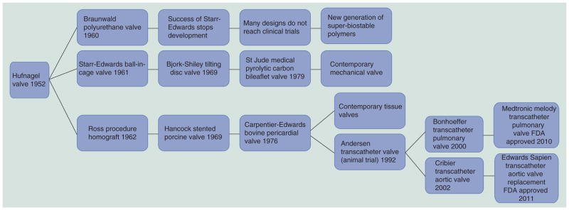
Timeline of prosthetic heart valve evolution focused on designs used in humans.
A silastic trileaflet PHV was described by Mori et al. in 1973 [43]. Imamura and Kaye described expanded-polytetrafluoroethylene (PTFE) trileaflet PHVs in 1977 and their failure in dogs [44]. In 1982 Wisman et al. described a PU-polymer heart valve (PHV) [45] and Kiraly et al. described a Hexsyn trileaflet PHV for use in a pulsatile left ventricular assist device (LVAD) [46]. Woo et al. described the poor in vitro hydrodynamic performance of ABIOMED’s valves in 1983 [47,48]. Hilbert et al. demonstrated in vivo calcification of PU-PHVs in sheep in 1987 [49]. Chandran et al. measured the in vitro hydrodynamics of a PU-PHV and found them to be comparable with a pericardial THV in 1989 [50,51]. In 1990, Nistal et al. demostrated the in vivo failure and calcification of PTFE-PHVs in sheep [52]. A group at the University of Leeds developed a PU valve and reported good in vitro hydrodynamics in 1996 [53]. Similarly, a group at the University of Glasgow (Scotland, UK) developed a PU-PHV and reported on several testing aspects up to in vivo sheep trials in 2001 that showed good results; however, the valves were implanted in the mitral valve position [54]. Leo et al. demostrated the poor hydrodynamics of Aortech PU valves in 2005 [55]. Eventually, a key finding was that the ether groups on PUs are susceptible to in vivo oxidization and subsequent hydrolysis, especially under flexion [56]. Given the steady improvement in the usable lifespan of THVs [57], the bar for regulatory approval of PHVs has been raised in terms of durability. As such, if PHVs cannot meet or exceed the performance (safety and effectiveness) of THVs currently on the market, then there is limited rationale or drive to approve their use in humans. However, a new generation of polymeric materials has been developed that in initial testing shows great promise for meeting the structural demands and design requirements for successful next-generation PHVs. This material, and new PHV concepts, will be described below.
Numerical studies in trileaflet valves
Numerical simulations in prosthetic heart valves have emerged in recent years. However, trileaflet valves, have received relatively sparse attention in the literature compared with their mechanical counterparts. Initial numerical models studied THVs using 2D computational fluid dynamics (CFD) by simulating steady turbulent flow through valves with varying degrees of stenosis [58,59]. 3D fluid–structure interaction (FSI) numerical simulations of the AV started emerging over the years, notably by De Hart et al. [60] and Carmody et al. [61]. Carmody et al. used the immersed boundary method (IBM) with the arbitrary Lagrangian–Eulerian (ALE) approach [62] to simulate the entire cardiac cycle of the AV using a LV model [63] to drive flow. The IBM solves the Navier–Stokes equations on an Eulerian grid relative to Lagrangian points but its accuracy depends upon the grid density and there is no coupling of information at the fluid-solid interface [62]. In Lagrangian algorithms, each node of the computational mesh follows the associated material particle during motion (solid mechanics). In Eulerian algorithms, the computational mesh is fixed and the continuum moves with respect to the grid (fluid mechanics). The ALE method combines these two techniques and allows greater continuum distortions while maintaining a clear boundary between fluid and solid phases [64]. De Hart et al. used a version of the IBM called the fictitious domain method (FDM) to simulate the movement of the AV throughout the cardiac cycle [65]. The FDM overcomes the complexity of adaptive fluid meshing by allowing independent discretizations of the computational domains so that the fluid mesh is not distorted by the submerged structures, and remeshing and ALE methods are not needed; however, the result is a less than accurate solution. Recently, a FSI simulation of a PU-PHV was reported for 50 μs of forward flow using the ALE approach with the sequential weak coupling method [66]. The authors currently employ a fully coupled sharp interface method (SIM) for FSI for better realism and accuracy [67]. In the SIM, the fluid structure interface is segregated by two distinct meshes (solid and fluid) with a defined traceable boundary. It requires adaptive fluid remeshing every ‘n’ time steps to avoid mesh distortions, but yields the most accurate information about valve dynamics and the fluid behavior near the valve.
Dwyer et al. reported what appears to be the first CFD study of the Sapien transcatheter valve [68]. The valve, aortic root and sinuses of Valsalva were modeled as rigid, and the valve was meshed separately in situ. The aorta was given an arbitrary curvature. The valve stent was ignored, and the valve and root were bound to prevent paravalvular leakage. They also modeled moderate and severe stenosis. Physiologic pressure was used to drive flow (120/80 mmHg). The output was ejection force, which even in severe stenosis was only a third of the diastolic force on the valve in vivo. Sun et al. has been using uncoupled structural finite element analysis (FEA) and CFD to evaluate tissue transcatheter and standard valves, including particle stress accumulation [69,70] utilizing a previously validated structural model of a bovine pericardial valve [71].
Design & testing considerations for PHV
A thorough analysis of the human aortic valve was performed by Thubrikar et al. [72]. The native AV has a complex hemispherical (semilunar) geometry with three leaflets each composed of distinct tissue layers including (from the aortic surface to the ventricular surface): the lamina fibrosa, a ridged collagen-rich layer; the lamina spongiosa, a disorganized connective tissue; and the lamina ventricularis, a thin elastin-rich layer. This tissue organization allows the AV to open and close under high loads virtually without failure approximately 1.5 billion times in a lifetime. The technology to create a flexible artificial structure with such durability is still wanting. Since the valve bears the greatest load during diastole, collagen fibers are arranged in the circumferential direction to provide strength while elastin is arranged in the radial direction to facilitate full valve closure. The thickness of the leaflets varies across its radial and circumferential dimensions. The attachments and free edges of the leaflets are thicker than the belly. The design of PHVs attempts to mimic this architecture; however, geometries to date still utilize uniform-thickness leaflets. The authors aim to customize the leaflet thickness via an optimization process that leads to the reduction of stress concentrations with an anticipated increase in both the durability and flexibility of the valve’s leaflets.
Important design parameters for PHVs include effective orifice area, jet velocity, pressure gradient, regurgitation and thrombogenic potential. Other design parameters include valve strut postcurvature, sewing ring, leaflet coaptation height, commissure gap, leaflet thickness, rounding hard edges, built-in regurgitant flow or ‘wash out’, and geometries considered for the leaflets (e.g., based on collapsing cylinder vs hemispherical, and so on) (Figure 2). For trileaflet polymer valves, optimization of leaflet thickness for maximimal durability and flexibility, in particular, remains a major design parameter.
Figure 2.

Geometric features of a trileaflet prosthetic heart valve.
The specific design of a prosthetic heart valve depends upon its intended use. As PHVs are likely to be advantageous for TAVR, in this disucssion we will focus on this application. Although emulating the precise architecture of the native AV is not absolutely necessary, as various geometrical configurations can achieve AV functional design goals (e.g., as in MHV – typically a bileaflet design with the leaflets opening and closing in the opposite direction of the native AV leaflets), PHVs lend themselves more readily to mimic the native AV trileaflet structure and geometry. As such, PHVs thus may benefit from the improved hemodynamics that such an architecture offers. General design considerations for successful prosthetic AV performance may be aided by the Draft Guidance for Industry and FDA Heart Valves – Investigational Device Exemption and Premarket Approval Applications document and ISO 5840: 2005 Cardiovascular Implants-Cardiac Valve Prostheses standards [201,202]. In general, the valve must survive in a highly dynamic and corrosive environment for several years. Briefly, the FDA guidelines indicate the minimum durability requirement for flexible valves to be 200 million cycles, simulating approximately 5 years of use, with a back pressure of 125 mmHg. Valves must have a nonpathological pressure gradient during forward flow, so as not to ‘over work’ the LV and must also not allow pathological regurgitant flow to prevent ventricular volume loading and overfilling.
Generally, the FDA requires that the preclinical testing of a prosthetic heart valve includes: material property testing, biological safety, hydrodynamic performance, structural performance, device durability, component fatigue assessments and device-specific testing. Biocompatibility testing according to ISO-10993, Biological Evaluation of Medical Devices Part 1: Evaluation and Testing, for blood-contacting, long-term implanted devices must be conducted (as discussed above). Additional recommended tests include component fatigue testing (600 million cycles), corrosion testing for exposed metals, failure-mode analysis, magnetic resonance safety and shelf life. Preclinical animal trials are conducted, under FDA 21 CFR 58, employing Good Laboratory Practice. In vivo hemodynamics should be assessed along with complete blood counts and chemistries including serum calcium and phosphorus. Necropsy and histology should be performed on explanted valves.
As PHVs are fabricated from biomaterials that may activate elements of the coagulation cascade, leading to both contactand flow-induced platelet activation, it is essential to test the thrombogenicity of both the material and the hemodynamics resulting from the valve’s structural and functional components. In prosthetic devices, this becomes a major design and optimization consideration. Flow-induced coagulation is initiated by elevated shear, turbulent stresses, and pathological flow patterns generated by diseased valves or implanted cardiovascular devices. While platelet activation is usually induced by biochemical agonists, platelets are highly sensitive to mechanical forces as well. Pathological flow disturbances and elevated shear stresses may induce platelet activation resulting in thrombus formation and embolization, leading to peripheral ischemia and stroke [73]. Biomaterial hemocompatibility depends on surface characteristics, including hydrophilicity (less adsorption), hydrophobicity (more adsorption), surface charge and surface free energy, all of which influence protein adsorption and denaturation during the initial response to material–blood contact. The activation of platelets on biomaterials is surface-initiated and primarily depends on the composition of the adsorbed protein layer [74]. Remarkably, there is no clear consensus on how to measure blood compatibility or what constitutes a hemocompatible material [75]. In the absence of clear guidelines for hemocompatibility testing, ISO 10993–4 (2002) may be used for guidance. Ultimately, methods must be developed that are more material specific and reflective of the operating environment of the device (e.g., testing static contact activation vis-à-vis under the same flow conditions, which materials should serve as positive and negative controls, and so on).
Hemostatic mechanisms designed to arrest bleeding from injured blood vessels mediated by tissue factor (extrinsic pathway) may also be activated in the presence of artificial or foreign materials. This process involves a complex series of interdependent events involving the material surface, platelets, coagulation proteins, thrombus formation and fibrinolysis. Platelets initially arrest bleeding by localizing to the agonist material or injury site, forming a plug. The physical bulk of clot formation is then propogated by catalyzing coagulation reactions that lead to the formation of fibrin, creating a meshwork that further entraps cellular elements [76]. This may be relevant during TAVR. Blood coagulation is a complex process involving a cascade of steps and feedback loops [77]. The two mechanisms for the initiation of coagulation most relevant to PHVs following implantation are contact- and flow-induced platelet activation. Contact-induced platelet activation occurs via the intrinsic coagulation system, initiated via factor XII adsorption to an artificial surface. Calcium is not required for this phase. Interestingly, a deficiency in factor XII leads to decreased thrombosis in the vasculature and increased activated partial thromboplastin time, without an associated increased risk for bleeding from injury, making factor XII an attractive target for the development of new anticoagulant drugs [78–80]. New studies indicate that factor XII-mediated contact activation is elicited by activated platelets contributing to clot formation, thus platelet activation triggers factor XII-mediated contact activation on the surface in the vicinity of activated platelets [81].
The common pathway of coagulation is mediated by factor Xa and its interaction with activated platelets and factor Va (mostly secreted from the activated platelets). This process occurs on the surface of activated platelets and platelet aggregates, which express anionic phospholipids, and is mediated by Ca2+. Factor Xa generates the prothrombinase complex, which converts prothrombin into thrombin. The generated thrombin in turn feeds back to reactivate platelets and catalyzes the conversion of soluble fibrinogen (Fg) from plasma into insoluble fibrin, which enmeshes red blood cells and platelets to form the physical bulk of an effective thrombus (blood clot) necessary for hemostasis. Besides prior activation of platelets, the availability of coagulation factors and efficacy of the prothrombinase reactions in the common pathway is additionally goverened by flow-mediated transport processes. Our modified prothrombinase platelet activation state (PAS) assay is based on blocking the positive feedback activity of thrombin [82]. This facilitates establishment of a direct correspondence between the agonist (e.g., flow-induced stresses leading to platelet activation) and the procoagulant activity of the platelets (expressed in terms of thrombin generation rates in the assay).
Next-generation polymeric materials for PHVs
PHVs create an option for an optimized heart valve implant. Key functional targets of an optimized PHV include: allowance of hemodynamically consistent blood flow, retention of structural durability under cyclic load-bearing conditions in a fluid environment and maintenance of blood compatibility, obviating the need for life-long anticoagulation [83]. Polymer surface and structural properties both play critical roles as design parameters with key variables including: backbone chemical bond stability towards degradation, thermal properties such as glass transition temperature (Tg), melting temperature (Tm), heat of fusion (ΔHf), distribution of Tg, Tm, percentage crystallinity and size of crystalline, and amorphous domains, and the percentage hard domain and size of the hard domain [83,84]. State of linearity of the backbone and branching of the chains are also important structural variables; for example, cyclic chain extenders in PUs demonstrate high Tg but low tensile strength [83]. In the case of PUs, backbone architecture of the soft segment is very important so as to prevent hydrolytic and oxidative degradation, and to reduce the potential for environmental stress cracking failure. Several new and improved polymeric materials are being investigated for use in PHVs. These material-include: the first biostable PU: polycarbonate urethane such as Bionate [85], a nanocomposite polymer comprised of polyhedral oligomeric silsesquioxane nanoparticles and polycarbonate urethane [86]; PU with a poly(dimethylsiloxane) soft segment known as Elast-Eon™ by AorTech Biomaterials [87]; Pellethane® 2363-80AE elastomer is a polytetramethylene glycol-based PU elastomer, by Lubrizol [42]; the tri-block copolymer thermoplastic polyolefin poly(styrene-block-isobutylene-block-styrene [SIBS]), held by Boston Scientific [56]; and the new polyolefin thermoset elastomer xSIBS by Innovia LLC [88]. Other polymers that can potentially be used in heart valve embodiments include fluoropolymers such as polyvinylidene difluoride and poly(vinylidene fluoride-co-hexafluoropropene) [89]; hyperbranched PUs demonstrating shape memory property [90]; and a nano-organic clay–PU composite [91]. These polymers offer improved biostability over previous generations. SIBS in particular appears to be one such ‘super-biostable’ polymer, showing high resilience to in vivo degradation, as described in the following.
SIBS & PHV fabrication
We have had extensive experience with SIBS in PHV development. The thermoplastic elastomer SIBS, invented at the University of Akron (OH, USA) by Kennedy et al. [92] and licensed and improved by Corvita Corp. (now owned by Boston Scientific) was specifically developed to eliminate the in vivo degradation of PUs. SIBS has no reactive pendant groups, rendering it hydrolytically, oxidatively and enzymatically stable [56]. In testing to date, no evidence of in vivo degradation has been observed. SIBS has been commercialized as a coating material for a drug-eluting stent by Boston Scientific (Taxus®), for local, contact-mediated, arterial wall delivery of paclitaxel following balloon angioplasty to prevent postdilatation restenosis [93]. Furthermore, it has been developed for PHV and ophthalmological uses by Innovia LLC (FL, USA) [94,95]. As SIBS is an elastomer with low tensile strength and relatively high dynamic creep [96], it has been strengthened with regard to its potential use in PHV leaflets through the incorporation of a polyester mesh (Dacron, CR Bard) [95]. The first composite SIBS-Dacron valve was fabricated via dip coating Dacron with dissolved SIBS. This resulted in incomplete encapsulation of the Dacron and promoted platelet activation as observed in our in vitro flow loop studies [97]. The next design iteration was improved via casting, so as to completely encapsulate the Dacron mesh to prevent blood contact. The composite leaflet material was affixed via braided polyester sutures into a high styrene content molded SIBS stent. Human platelet adhesion studies, performed using whole blood in a parallel plate flow system, have revealed low platelet adhesion, especially on phospholipid-modified SIBS sheets [98]. Animal model biocompatibility testing of SIBS-coated teflon sutures found no appreciable in vivo reactions [99]. The authors performed in vitro isolated human platelet activation testing of the improved cast leaflet design in comparison to a gold-standard THV in a small volume, pulsatile, flow loop using our modified prothrombinase PAS assay and flow cytometry via P-selectin [100]. Our results indicated that the platelet activation rate in the SIBS valve measured by PAS is fivefold lower than the THV. Additionally, in vitro hydrodynamics testing demonstrated a close approximation to the pressure gradient and regurgitation of the THV, with fatigue testing and FEA predicting a life span approximating 10 years [101]. With these positive test results, pre-clinical animal studies were conducted utilizing the sheep model. Animal studies unfortunately revealed cracking of the SIBS coating via dynamic creep, allowing reaction with the underlying Dacron to occur, resulting in thrombosis, calcification and tissue in-growth (Figure 3) [102]. In parallel, the authors developed and evaluated a novel self-expandable transcatheter valve designed for AV replacement, comprised of the SIBS-Dacron composite and Nitinol wire, with a complementary delivery system (Figure 4). The authors also formulated a method for in vitro testing of these devices. Our data demonstrated good hydrodynamic performance and in situ fixation of the final prototype [103].
Figure 3. The original SIBS-Dacron composite prosthetic heart valve design showing (A) stress concentration along its leaflets and (B–D) the in vivo failure mode.
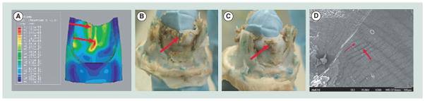
Adapted with permission from [104].
Figure 4. A self-expanding SIBS-Dacron-based transcatheter valve developed by our group.
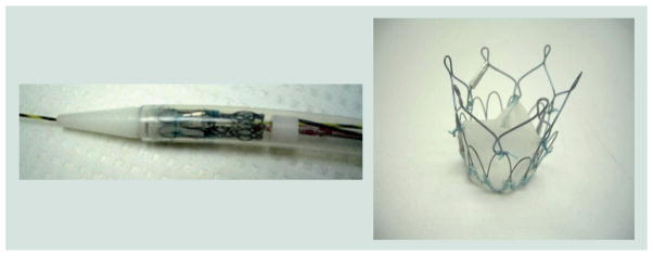
Adapted with permission from [105].
Application of PHVs for TAVR
As TAVR is just emerging in the clinical domain, its current utilization is somewhat restricted. As limited data exist with regard to the long-term clinical durability of percutaneous valves, TAVR to date has been focused on the inoperable elderly patient. The PARTNER clinical trial data, with a mean age of 83 years and maximum follow-up time of 2.8 years, demonstrated that TAVR was better than conventional medical treatment for inoperable patients suffering from significant AS [104], which resulted in the granting of FDA regulatory approval. Interestingly, recent evidence indicates that tissue-based transcatheter valves are damaged by the present crimping and delivery process, which may increase their rate of SVD [28]. Some have begun to investigate tissue-engineering strategies to mitigate tissue damage but results from these investigations remain far from clinical reality [105,106]. Therefore, it is reasonable to assume that flexible polymeric valves better able to withstand the stresses involved in TAVR crimping and deployment, coupled with durability and effective hemodynamic performance, may be a viable alternative to present tissue valves utilized in TAVR. Furthermore, we may be able to achieve lower profile TAVR valves and delivery catheter systems, which would allow peripheral artery access in a larger patient population, reducing the need for surgical cut-down for arterial access. Indeed, others are already developing PHVs for TAVR [107]. If clinical PHV viability and durability are demonstrated, it may be possible to introduce open-heart PHVs as well, with long-term durability and decreased thrombogenicity compared with THVs and MHVs, respectively.
In a transcatheter valve, the leaflets function like a collapsing cylinder, tethered at three equidistant points near the leaflet free edge. Several methods of attachment and stent design may therefore be utilized. A list of important design requirements and features for polymeric transcatheter valves and the desired outcomes of such designs are presented in Table 3. Key design considerations include ease of implantation, crimped profile, radio-opacity, resistance to device migration or embolization, minimization of perivalvular leakage, and coronary ostia and mitral valve clearance, in addition to the other parameters listed above for open-heart valves.
Table 3.
Design and use requirements guiding the development of a safe and effective polymeric transcatheter valve.
| Design requirements | Desired features/outcomes |
|---|---|
| TAD 21 mm (small adult humans and sheep) | Ease of implantation |
| Mean pressure gradient ΔP <20 mmHg | Relief of symptomatic AS/AI |
| Mean regurgitant fraction <25% | Repositioning/retrievability |
| Maximum jet velocity <2.5 m/s | A therapy rather than palliative care |
| Effective orifice area >1cm2 | Nonimmunogenic |
| Durability >200 million cycles | Nontoxic |
| Thrombogenicity ≤THV | Nonpyrogenic |
| Crimped profile <22 F | Nonthrombogenic |
| Slippage pressure >100 mmHg | Free of degradation |
| Biocompatible | Free of calcification |
| Radio-opaque | No tissue in growth Absence of device migration No coronary ostia interference No perivalvular leakage |
AI: Aortic insufficiency; AS: Aortic stenosis; TAD: Tissue annulus diameter; THV: Tissue heart valve.
Alternative uses for PHVs
After more than 50 years of research and development, the SynCardia Total Artificial Heart (TAH; SynCardia Systems, Inc., AZ, USA) has emerged as the only FDA-approved bridge-to-transplant heart-replacement device available on the market [108]. In the first days of development of the TAH, it was envisioned and designed with an intended use as a destination therapy device for heart failure patients in lieu of heart transplantation [109,110]. Over time, for numerous technical and clinical reasons, it became clear that the initial goal was too ambitious. Following a clinical trial examining its use as a bridge-to-transplantation device, which took over a decade to complete, in 2004 the TAH received FDA approval. In April 2012, SynCardia announced that its TAH had also been granted designation by the FDA as a humanitarian use device for destination therapy. The utility of the TAH has expanded even further with its coupling to a new portable Freedom Driver system currently under an investigational device exemption, allowing discharge of patients from the hospital with full ambulation. With growing indications, the Syncardia’s TAH has become accepted as a viable, life-saving clinical therapy in the treatment of advanced biventricular heart failure. The current TAH utilizes monoleaflet MHVs (Medtronic Hall), which in the near term are planned to be substituted with bileaflet MHVs. In the future, PHVs may have utility in the TAH to further increase the thromboresistance of the device, reduce the need for anticoagulation and at the same time decrease the audible sounds of present MHVs. Others have also investigated the use of PHVs in pulsatile VADs, an additional potential use for PHVs [111]. PHVs are imminently scalable and could be utilized in pulsatile pediatric VADs that currently employ MHVs [112].
The use of xSIBS in a novel PHV
In order to mitigate the failure of SIBS due to dynamic viscoelastic creep (change in strain over time under a dynamic stress below the yield stress), Innovia LLC (FL, USA) has formulated the proprietary insoluble and infusible thermoset known as xSIBS [88]. The authors are currently investigating xSIBS as a material for a novel PHV. In formulating xSIBS, a coupling reaction, catalyzed by benzocyclobutene that causes polymer backbones to crosslink via a Diels–Alder reaction, is employed. Raw xSIBS is heated (240°C for 30 min) and compressed in the absence of oxygen to make thin films and prototypes for testing. Initial tensile testing has shown that xSIBS has a large elastic range and a high ultimate strength, making it a hyper elastic rubber-like material.
Optimization of PHV using device thrombogenicity emulation methodology
The authors are currently evaluating the material–platelet contact activation potential of xSIBS using the device thrombogenicity emulation (DTE) methodology developed in our laboratory employing a programmable cone-plate-couette viscometer device referred to as the hemodynamic shearing device (HSD) [113]. We are also optimizing a valve design for flexibility, durability and thrombogenicity by altering key parameters of the geometry, such as variable leaflet thickness, leaflet curvature, leaflet coaptation surface area, profile and stent geometry. In this design phase, the authors have employed our DTE methodology of evaluation of the valve performance following an iterative optimization process (Figure 5) [114,115]. The goal of DTE is to minimize, and ideally eliminate, the need for anticoagulants in blood-contacting medical devices. The authors have extended this optimization methodology in trileaflet PHVs to include FEA for the structural stress minimization on the valve’s leaflets, as described below.
Figure 5. Device thrombogenicity emulation process involves the combination of numerical (CAD, CFD, FEA) and experimental methods (hemodynamic shearing device-platelet activation).

The device thrombogenicity emulation (DTE) process involves the combination of numerical (CAD, CFD, FEA) and experimental methods (hemodynamic shearing device-platelet activation). CAD: Computer aided design; CFD: Computational fluid dynamics; FEA: Finite element analysis; Fg: Fibrinogen; FSI: Fluid–structure interaction; PAS: Platelet activity state; vWF: von Willebrand factor.
DTE combines numerical studies with experimental platelet activation measurements in order to identify and modify undesirable design features that contribute to flow-induced platelet activation and thrombosis. We employ computer-aided design (CAD), FEA, two-phase (particle and fluid) CFD and FSI simulations, coupled with platelet activation (Figures 5–8) measurements using the PAS assay with the large HSD, where stress loading waveforms extracted from geometry-specific ‘hot spot’ regions of interest (ROI) are emulated (Figure 5), as previously described [116,117]. In order to characterize the global thrombogenicity of the device, the authors collapsed the calculated stress accumulation (SA) information from approximately 50,000 platelets into a kernel-smoothened probability density function (PDF) of the SA to obtain distribution curves that can be compared side-by-side, coined the ‘thrombogenic footprint’ of the specific device design iteration. The dominant mode of the thrombogenic footprint indicates in which SA range the majority of platelets passing through the device reside, allowing a side-by-side comparison of different designs (Figure 9). ROIs are identified within the flow field through the device by inspecting the velocity vector flow field at planar sections, the 3D platelet dispersion patterns and specific platelet trajectories. Regions of the device that create high-velocity jets and shear layers are of special interest, as they tend to generate the highest SA values (potential for platelet activation) and typically correlate with constricted flow regions. Platelets passing through these regions experience very high instantaneous shear stress, and the time that they spend in that region increases their stress accumulation. For trileaflet valves, the ROIs are typically the three commissures and the core, during distinct cardiac cycle phases of the forward flow through the open valve (peak systole) and regurgitant flow through the closed valve (mid-diastole). During the iterative design, optimization process-improved designs show a shift of the dominant mode toward lower SA values, with a lower number of platelets residing in the higher and riskier SA range. This process may be repeated iteratively to achieve full optimization prior to prototype fabrication and testing.
Figure 8. Computational fluid dynamics velocity (m/s) flow field comparison of the Aortech PU-polymeric heart valves, Innovia SIBS-Dacron composite polymeric heart valves, and a bovine pericardial tissue heart valves.

In forward flow, the Carpentier-Edwards Perimount Magna tissue valve exhibited the highest velocity jet and in regurgitant flow, the Innovia SIBS-Dacron composite exhibited the highest velocity jets.
Figure 9. ‘Thrombogenic footprint’ comparison of the Innovia Composite valve to the Aortech PU and Carpentier-Edwards Perimount Magna tissue valves.

In forward flow, the advantage goes to the Innovia valve, which was designed for maximum flexibility, while in regurgitant flow the advantage goes to the Aortech valve, which was designed for greater ‘wash-out’ flow.
HSD: Hemodynamic shearing device; FF: Forward flow; RF: Regurgitant flow.
The HSD platelet studies serve as an experimental surrogate of the CFD and facilitate experimental comparison of various designs and/or devices before the optimized design prototype is fabricated and tested (Figure 10). Briefly, platelet experiments are performed utilizing a large HSD, which is a high-torque (13.3 Nm), fast response (3 ms), programmable coneplate-couette viscometer that is capable of emulating highly dynamic platelet stress loading waveforms, reaching instantaneous shear stresses up to 900 dynes/cm2. In order to select representative ‘hot spot’ loading waveforms for HSD emulation, the SA along hundreds of platelet trajectories passing through an ROI, which is characterized by higher SA values, is computed and used to plot the PDF in the specific ROI. The most frequent SA in the subset is identified and a trajectory with the representative SA is then selected for emulation in the HSD.
Figure 10.

Comparative hemodynamic shearing device platelet activation state measurements in several prosthetic heart valve: Aortech, Innovia SIBS-Dacron Composite and Carpentier-Edwards Perimount Magna tissue valve with the platelet stress loading waveforms emulated in the hemodynamic shearing device shown.
FEA studies feed geometries into CFD and inform us about the structural stress concentrations developed in a particular design during different phases of its duty cycle.
Once the design is considered optimized (i.e., significant reduction in high stress concentration regions in the valve leaflets, significantly reduced thrombogenicity, and so on), the iterative optimization process is frozen and one may proceed to prototype fabrication. In the case of the xSIBS-based PHV, the authors are studying and have selected five-axis computer numerical control-machined compression molding in order to create the precise geometric features of the optimized design that cannot be achieved with the dip-coating or casting processes typically used for PHV fabrication. Compression molding also facilitates the thermal crosslinking process for xSIBS. Prototypes will then be put through the rigorous in vitro testing required by the FDA and ISO standards, including hydrodynamics, durability and bulk-flow platelet activation. The best prototypes to emerge will then be studied in large-animal, preclinical trials, examining functional efficacy as well as material durability, degradation and thrombogenicity to determine if optimization translates into enhanced performance in vivo.
Expert commentary
Since the initial description of prosthetic heart valves in 1951, a clinically successful, flexible tri-leaflet PHV has not yet been realized. This is largely due to both the success of mechanical and tissue valves, and the limitations of available polymers. The main hurdles underlying the potential clinical emergence of PHVs are in vivo durability and thrombotic complications. Those, combined with the high bar for regulatory approval, have to date curbed the advent of these promising valves. Advanced polymers that have become available more recently with improved durability and biostability over prior generations, combined with an effective optimization methodology, will likely finally help overcome the hurdles that have limited PHVs, allowing them to become clinically viable. Presently, it appears that the best pathway forward for PHVs will be via utilization in TAVR. TAVR has recently become FDA-approved for inoperable patients with severe AS. As this patient population is typically elderly, with a mean age of 83 years, the long-term durability requirement for first-generation PHVs may be somewhat reduced. Indeed, no long-term clinical data for TAVR currently exist. The authors may also be able to achieve lower profiles with PHVs in TAVR, which will allow utilization of smaller French size catheters, reducing the potential for peripheral arterial complications, a significant issue with present large-caliber systems. If durability is proven with PHVs in TAVR patients, this may eventually lead to follow-on approval for open-heart surgical implantation designs, providing an alternative to present tissue and mechanical valves, offering the potential for reduced thrombotic and bleeding risk, and reducing the need for chronic anticoagulation, and reduced reoperation risk due to SVD.
The DTE methodology, combining state-of-the-art numerical simulations with experimental validation, allows us to optimize the functionality, durability and thromboresistance of PHVs prior to prototype fabrication and testing. This enhanced methodology will shorten the time and reduce the costs of device development. Newer polymer formulations currently being tested offer great promise over prior polymeric materials that have been explored. The novel thermoset xSIBS holds great promise for use in the PHV-TAVR application, in that it combines hyperelasticity with low platelet activation. Furthermore, it affords the fabrication of a homogenous valve, a significant improvement over the prior SIBSDacron composite design. Utilizing this new material, combined with the described optimization methodology offers the greatest state-of-the art chance for finally bringing a safe, effective, durable and nonthrombogenic PHV into clinical reality.
Five-year view
The limitations of mechanical and tissue valves have been thoroughly researched over several decades and the need for an alternative device is clear, especially given the advent of the TAVR procedure. Several groups are working on newer, more biostable state-of-the-art polymers for application in PHVs. We are now closer than ever to realizing the development of a successful trileaflet PHV. Over the next 5 years we expect to see a novel design emerge into clinical testing. If these newer materials and designs with their intrinsic bio- and hemo-compatibility advantages prove safe and efficacious, then this will truly emerge as a disruptive technology in the field of prosthetic heart valves. We envision that several PHV designs may then move forward toward gaining regulatory approval. Solutions will also be sought and developed for valve-associated problems relevant to transcatheter valve implantation; that is, perivalular leakage, device placement and diseased valve resection.
Figure 6.

Finite element analysis of diastolic pressure loading (80 mmHg) showing the optimization achieved by tapering the leaflet thickness showing reduced stress concentrations in the optimized design (all stress color scales identical).
Figure 7. Fluid–structure interaction analysis of the original innovia composite prosthetic heart valve showing images from systole.

(A) Wall shear stress near the leaflet-free edge, (B) structural stress map of the valve, (C) velocity profile of the flow field and (D) velocity vector flow field.
Key issues.
In vivo durability and hemocompatibility (nonthrombogenicity) remain the most significant hurdles for trileaflet polymeric heart valves (PHVs) emerging into clinical reality.
-
Optimizing PHV geometry during the design phase is essential as it affects durability, hemodynamics and thrombogenicity.
Optimization can achieve the reduction of stresses that the leaflets endure during opening and closing during the cardiac cycle, while increasing their flexibility to achieve a larger valve orifice.
While computational efforts for the demanding numerical simulations in flexible trileaflet PHVs are challenging, they are essential for realization of successful future designs.
Strategies that combine numerical and experimental approaches such as the device thrombogenicity emulation are efficacious and offer the best chance for achieving such optimization.
In present transcatheter aortic valve replacement, xenograft tissue (e.g., leaflet) damage is of concern, in that it may affect long-term valve durability and functionality, making an effective PHV an attractive alternative for this application.
PHVs may also find utility and offer functional advantages in other cardiovascular devices such as pulsatile ventricular assist devices and the total artificial heart, compared with present day mechanical heart valves.
Regulatory approval for a PHV will remain challenging; however, utilization in a transcatheter aortic valve replacement application may be the least burdensome pathway forward.
Footnotes
For reprint orders, please contact reprints@expert-reviews.com
Financial & competing interests disclosure
The authors’ work is supported by the NIH-NIBIB (National Institute of Bioimaging and Bioengineering) via a Quantum Implementation Phase II award (1U01EB012487-0, DB). MJ Slepian is Founder and Chief Scientific Officer of SynCardia Systems, Inc. S Hossainy is Director of the Innovation Incubator and Volwiler Research Fellow at Abbott Vascular. The authors have established a research collaboration with Innovia LLC (FL, USA). Both companies and all authors participate in the NIH-NIBIB Quantum project. The authors have no other relevant affiliations or financial involvement with any organization or entity with a financial interest in or financial conflict with the subject matter or materials discussed in the manuscript apart from those disclosed.
No writing assistance was utilized in the production of this manuscript.
References
Papers of special note have been highlighted as:
• of interest
•• of considerable interest
- 1.Rosamond W, Flegal K, Friday G, et al. American Heart Association Statistics Committee and Stroke Statistics Subcommittee. Heart disease and stroke statistics – 2007 update: a report from the American Heart Association Statistics Committee and Stroke Statistics Subcommittee. Circulation. 2007;115(5):e69–e171. doi: 10.1161/CIRCULATIONAHA.106.179918. [DOI] [PubMed] [Google Scholar]
- 2.Kurtz CE, Otto CM. Aortic stenosis: clinical aspects of diagnosis and management, with 10 illustrative case reports from a 25-year experience. Medicine (Baltimore) 2010;89(6):349–379. doi: 10.1097/MD.0b013e3181fe5648. [DOI] [PubMed] [Google Scholar]
- 3.Chandran KB, Rittgers SE, Yoganatha AP. Biofluid Mechanics: The Human Circulation. Vol. 419. CRC/Taylor & Francis; FL, USA: 2007. [Google Scholar]
- 4.Akat K, Borggrefe M, Kaden JJ. Aortic valve calcification: basic science to clinical practice. Heart. 2009;95(8):616–623. doi: 10.1136/hrt.2007.134783. [DOI] [PubMed] [Google Scholar]
- 5.Helske S, Kupari M, Lindstedt KA, Kovanen PT. Aortic valve stenosis: an active atheroinflammatory process. Curr Opin Lipidol. 2007;18(5):483–491. doi: 10.1097/MOL.0b013e3282a66099. [DOI] [PubMed] [Google Scholar]
- 6.Hermans H, Herijgers P, Holvoet P, et al. Statins for calcific aortic valve stenosis: into oblivion after SALTIRE and SEAS? An extensive review from bench to bedside. Curr Probl Cardiol. 2010;35(6):284–306. doi: 10.1016/j.cpcardiol.2010.02.002. [DOI] [PubMed] [Google Scholar]
- 7.Rajamannan NM, Evans FJ, Aikawa E, et al. Calcific aortic valve disease: not simply a degenerative process: a review and agenda for research from the National Heart and Lung and Blood Institute Aortic Stenosis Working Group. Executive summary: Calcific aortic valve disease – 2011 update. Circulation. 2011;124(16):1783–1791. doi: 10.1161/CIRCULATIONAHA.110.006767. [DOI] [PMC free article] [PubMed] [Google Scholar]
- 8.Parolari A, Loardi C, Mussoni L, et al. Nonrheumatic calcific aortic stenosis: an overview from basic science to pharmacological prevention. Eur J Cardiothorac Surg. 2009;35(3):493–504. doi: 10.1016/j.ejcts.2008.11.033. [DOI] [PubMed] [Google Scholar]
- 9.Holmes DR, Jr, Mack MJ, Kaul S, et al. American College of Cardiology Foundation; American Association for Thoracic Surgery; Society for Cardiovascular Angiography and Interventions; Society for Thoracic Surgeons; American Heart Association; American Society of Echocardiography; European Association for Cardio-Thoracic Surgery; Heart Failure Society of America; Mended Hearts; Society of Cardiovascular Anesthesiologists; Society of Cardiovascular Computed Tomography; Society for Cardiovascular Magnetic Resonance. 2012 ACCF/AATS/SCAI/STS expert consensus document on transcatheter aortic valve replacement: developed in collaboration with the American Heart Association, American Society of Echocardiography, European Association for Cardio-Thoracic Surgery, Heart Failure Society of America, Mended Hearts, Society of Cardiovascular Anesthesiologists, Society of Cardiovascular Computed Tomography, and Society for Cardiovascular Magnetic Resonance. Ann Thorac Surg. 2012;93(4):1340–1395. doi: 10.1016/j.athoracsur.2012.01.084. [DOI] [PubMed] [Google Scholar]
- 10.Rahimtoola SH. Choice of prosthetic heart valve in adults an update. J Am Coll Cardiol. 2010;55(22):2413–2426. doi: 10.1016/j.jacc.2009.10.085. [DOI] [PubMed] [Google Scholar]
- 11.McClure RS, Narayanasamy N, Wiegerinck E, et al. Late outcomes for aortic valve replacement with the Carpentier-Edwards pericardial bioprosthesis: up to 17-year follow-up in 1,000 patients. Ann Thorac Surg. 2010;89(5):1410–1416. doi: 10.1016/j.athoracsur.2010.01.046. [DOI] [PubMed] [Google Scholar]
- 12.Chaudhry MA, Raco L, Muriithi EW, Bernacca GM, Tolland MM, Wheatley DJ. Porcine versus pericardial bioprostheses: eleven-year follow up of a prospective randomized trial. J Heart Valve Dis. 2000;9(3):429–437. discussion 437. [PubMed] [Google Scholar]
- 13.Walther T, Falk V, Mohr FW. Minimally invasive surgery for valve disease. Curr Probl Cardiol. 2006;31(6):399–437. doi: 10.1016/j.cpcardiol.2006.02.002. [DOI] [PubMed] [Google Scholar]
- 14.Rosengart TK, Feldman T, Borger MA, et al. American Heart Association Council on Cardiovascular Surgery and Anesthesia; American Heart Association Council on Clinical Cardiology; Functional Genomics and Translational Biology Interdisciplinary Working Group; Quality of Care and Outcomes Research Interdisciplinary Working Group. Percutaneous and minimally invasive valve procedures: a scientific statement from the American Heart Association Council on Cardiovascular Surgery and Anesthesia, Council on Clinical Cardiology, Functional Genomics and Translational Biology Interdisciplinary Working Group, and Quality of Care and Outcomes Research Interdisciplinary Working Group. Circulation. 2008;117(13):1750–1767. doi: 10.1161/CIRCULATIONAHA.107.188525. [DOI] [PubMed] [Google Scholar]
- 15.Andersen HR. History of percutaneous aortic valve prosthesis. Herz. 2009;34(5):343–346. doi: 10.1007/s00059-009-3251-4. [DOI] [PubMed] [Google Scholar]
- 16.Kidane AG, Burriesci G, Cornejo P, et al. Current developments and future prospects for heart valve replacement therapy. J Biomed Mater Res Part B Appl Biomater. 2009;88(1):290–303. doi: 10.1002/jbm.b.31151. [DOI] [PubMed] [Google Scholar]
- 17.Bower JL, Christensen CM. Disruptive technologies – catching the wave. Harv Bus Rev. 1995;73:43–53. [Google Scholar]
- 18.Webb J, Cribier A. Percutaneous transarterial aortic valve implantation: what do we know? Eur Heart J. 2011;32(2):140–147. doi: 10.1093/eurheartj/ehq453. [DOI] [PubMed] [Google Scholar]
- 19.Davies H. Catheter-mounted valve for temporary relief of aortic insufficiency. Lancet. 1965;1:250. [Google Scholar]
- 20•.Andersen HR, Knudsen LL, Hasenkam JM. Transluminal implantation of artificial heart valves. Description of a new expandable aortic valve and initial results with implantation by catheter technique in closed chest pigs. Eur Heart J. 1992;13(5):704–708. doi: 10.1093/oxfordjournals.eurheartj.a060238. First transcatheter aortic valve replacement (TAVR) description. [DOI] [PubMed] [Google Scholar]
- 21••.Cribier A, Eltchaninoff H, Bash A, et al. Percutaneous transcatheter implantation of an aortic valve prosthesis for calcific aortic stenosis: first human case description. Circulation. 2002;106(24):3006–3008. doi: 10.1161/01.cir.0000047200.36165.b8. First in-human TAVR. [DOI] [PubMed] [Google Scholar]
- 22.Bonhoeffer P, Boudjemline Y, Saliba Z, et al. Percutaneous replacement of pulmonary valve in a right-ventricle to pulmonary-artery prosthetic conduit with valve dysfunction. Lancet. 2000;356(9239):1403–1405. doi: 10.1016/S0140-6736(00)02844-0. [DOI] [PubMed] [Google Scholar]
- 23.Azadani AN, Tseng EE. Transcatheter valve-in-valve implantation for failing bioprosthetic valves. Future Cardiol. 2010;6(6):811–831. doi: 10.2217/fca.10.106. [DOI] [PubMed] [Google Scholar]
- 24.Gurvitch R, Cheung A, Ye J, et al. Transcatheter valve-in-valve implantation for failed surgical bioprosthetic valves. J Am Coll Cardiol. 2011;58(21):2196–2209. doi: 10.1016/j.jacc.2011.09.009. [DOI] [PubMed] [Google Scholar]
- 25.Greif M, Lange P, Mair H, et al. Transcatheter Edwards Sapien XT valve in valve implantation in degenerated aortic bioprostheses via transfemoral access. Clin Res Cardiol. 2012 doi: 10.1007/s00392-012-0488-3. (Epub ahead of print) [DOI] [PubMed] [Google Scholar]
- 26.Toggweiler S, Wood DA, Rodés-Cabau J, et al. Transcatheter valve-in-valve implantation for failed balloon-expandable transcatheter aortic valves. JACC Cardiovasc Interv. 2012;5(5):571–577. doi: 10.1016/j.jcin.2012.03.008. [DOI] [PubMed] [Google Scholar]
- 27.Willson AB, Rodès-Cabau J, Wood DA, et al. Transcatheter aortic valve replacement with the St. Jude Medical Portico valve: first-in-human experience. J Am Coll Cardiol. 2012;60(7):581–586. doi: 10.1016/j.jacc.2012.02.045. [DOI] [PubMed] [Google Scholar]
- 28••.Zegdi R, Bruneval P, Blanchard D, Fabiani JN. Evidence of leaflet injury during percutaneous aortic valve deployment. Eur J Cardiothorac Surg. 2011;40(1):257–259. doi: 10.1016/j.ejcts.2010.11.010. First evidence of tissue valve damage in TAVR. [DOI] [PubMed] [Google Scholar]
- 29.de Buhr W, Pfeifer S, Slotta-Huspenina J, Wintermantel E, Lutter G, Goetz WA. Impairment of pericardial leaflet structure from balloon-expanded valved stents. J Thorac Cardiovasc Surg. 2012;143(6):1417–1421. doi: 10.1016/j.jtcvs.2011.11.001. [DOI] [PubMed] [Google Scholar]
- 30.Hufnagel CA. Plastic cardiac valvular prostheses. Am J Med. 1951;11:243–243. [Google Scholar]
- 31.Miller BJ, Gibbon JH, Jr, Greco VF, Smith BA, Cohn CH, Allbritten FF., Jr The production and repair of interatrial septal defects under direct vision with the assistance of an extracorporeal pump-oxygenator circuit. J Thorac Surg. 1953;26(6):598–616. discussion 631. [PubMed] [Google Scholar]
- 32.Gott VL, Alejo DE, Cameron DE. Mechanical heart valves: 50 years of evolution. Ann Thorac Surg. 2003;76(6):S2230–S2239. doi: 10.1016/j.athoracsur.2003.09.002. [DOI] [PubMed] [Google Scholar]
- 33.Ross DN. Homograft replacement of the aortic valve. Lancet. 1962;2(7254):487. doi: 10.1016/s0140-6736(62)90345-8. [DOI] [PubMed] [Google Scholar]
- 34.Kaiser GA, Hancock WD, Lukban SB, Litwak RS. Clinical use of a new design stented xenograft heart valve prosthesis. Surg Forum. 1969;20:137–138. [PubMed] [Google Scholar]
- 35.Carpentier A. From valvular xenograft to valvular bioprosthesis (1965–1977) Med Instrum. 1977;11(2):98–101. [PubMed] [Google Scholar]
- 36.Carpentier A. From valvular xenograft to valvular bioprosthesis: 1965–1970. Ann Thorac Surg. 1989;48(3 Suppl):S73–S74. doi: 10.1016/0003-4975(89)90646-2. [DOI] [PubMed] [Google Scholar]
- 37.Ten Berge L. A flexible cardiac valve prosthesis; preliminary report on the development of an experimental valvular prosthesis. Arch Chir Neerl. 1958;10(1):26–33. [PubMed] [Google Scholar]
- 38.Elliot EC, Callaghan JC. All plastic ventricle-type pump with tricuspid valves. Can J Surg. 1958;1(4):308–312. [PubMed] [Google Scholar]
- 39.Braunwald NS, Cooper T, Morrow AG. Complete replacement of the mitral valve. Successful clinical application of a flexible polyurethane prosthesis. J Thorac Cardiovasc Surg. 1960;40:1–11. [PubMed] [Google Scholar]
- 40.Maisano F, La Canna G, Colombo A, Alfieri O. The evolution from surgery to percutaneous mitral valve interventions: the role of the edge-to-edge technique. J Am Coll Cardiol. 2011;58(21):2174–2182. doi: 10.1016/j.jacc.2011.07.046. [DOI] [PubMed] [Google Scholar]
- 41.Ghanbari H, Viatge H, Kidane AG, Burriesci G, Tavakoli M, Seifalian AM. Polymeric heart valves: new materials, emerging hopes. Trends Biotechnol. 2009;27(6):359–367. doi: 10.1016/j.tibtech.2009.03.002. [DOI] [PubMed] [Google Scholar]
- 42.Kütting M, Roggenkamp J, Urban U, Schmitz-Rode T, Steinseifer U. Polyurethane heart valves: past, present and future. Expert Rev Med Devices. 2011;8(2):227–233. doi: 10.1586/erd.10.79. [DOI] [PubMed] [Google Scholar]
- 43.Mori H, Hessel EA, 2nd, Nelson RJ, Anderson HN, Dillard DH, Merendino KA. Design and durability test of Silastic trileaflet aortic valve prostheses. J Thorac Cardiovasc Surg. 1973;65(4):576–582. [PubMed] [Google Scholar]
- 44.Imamura E, Kaye MP. Function of expanded-polytetrafluoroethylene laminated trileaflet valves in animals. Mayo Clin Proc. 1977;52(12):770–775. [PubMed] [Google Scholar]
- 45.Wisman CB, Pierce WS, Donachy JH, Pae WE, Myers JL, Prophet GA. A polyurethane trileaflet cardiac valve prosthesis: in vitro and in vivo studies. Trans Am Soc Artif Intern Organs. 1982;28:164–168. [PubMed] [Google Scholar]
- 46.Kiraly R, Yozu R, Hillegass D, et al. Hexsyn trileaflet valve: application to temporary blood pumps. Artif Organs. 1982;6(2):190–197. doi: 10.1111/j.1525-1594.1982.tb04082.x. [DOI] [PubMed] [Google Scholar]
- 47.Woo YR, Williams FP, Yoganathan AP. Steady and pulsatile flow studies on a trileaflet heart valve prosthesis. Scand J Thorac Cardiovasc Surg. 1983;17(3):227–236. doi: 10.3109/14017438309099357. [DOI] [PubMed] [Google Scholar]
- 48.Woo YR, Williams FP, Yoganathan AP. In-vitro fluid dynamic characteristics of the abiomed trileaflet heart valve prosthesis. J Biomech Eng. 1983;105(4):338–345. doi: 10.1115/1.3138430. [DOI] [PubMed] [Google Scholar]
- 49.Hilbert SL, Ferrans VJ, Tomita Y, Eidbo EE, Jones M. Evaluation of explanted polyurethane trileaflet cardiac valve prostheses. J Thorac Cardiovasc Surg. 1987;94(3):419–429. [PubMed] [Google Scholar]
- 50.Chandran KB, Fatemi R, Schoephoerster R, et al. In vitro comparison of velocity profiles and turbulent shear distal to polyurethane trileaflet and pericardial prosthetic valves. Artif Organs. 1989;13(2):148–154. doi: 10.1111/j.1525-1594.1989.tb02850.x. [DOI] [PubMed] [Google Scholar]
- 51.Chandran KB, Schoephoerster RT, Wurzel D, et al. Hemodynamic comparisons of polyurethane trileaflet and bioprosthetic heart valves. ASAIO Trans. 1989;35(2):132–138. doi: 10.1097/00002480-198904000-00003. [DOI] [PubMed] [Google Scholar]
- 52.Nistal F, García-Martínez V, Arbe E, et al. In vivo experimental assessment of polytetrafluoroethylene trileaflet heart valve prosthesis. J Thorac Cardiovasc Surg. 1990;99(6):1074–1081. [PubMed] [Google Scholar]
- 53.Corden J, David T, Fisher J. The influence of open leaflet geometry on the haemodynamic flow characteristics of polyurethane trileaflet artificial heart valves. Proc Inst Mech Eng H. 1996;210(4):273–287. doi: 10.1243/PIME_PROC_1996_210_424_02. [DOI] [PubMed] [Google Scholar]
- 54.Wheatley DJ, Bernacca GM, Tolland MM, O’Connor B, Fisher J, Williams DF. Hydrodynamic function of a biostable polyurethane flexible heart valve after six months in sheep. Int J Artif Organs. 2001;24(2):95–101. [PubMed] [Google Scholar]
- 55.Leo HL, Simon H, Carberry J, Lee SC, Yoganathan AP. A comparison of flow field structures of two tri-leaflet polymeric heart valves. Ann Biomed Eng. 2005;33(4):429–443. doi: 10.1007/s10439-005-2498-z. [DOI] [PubMed] [Google Scholar]
- 56••.Pinchuk L, Wilson GJ, Barry JJ, Schoephoerster RT, Parel JM, Kennedy JP. Medical applications of poly(styrene-blockisobutylene-block-styrene) (‘SIBS’) Biomaterials. 2008;29(4):448–460. doi: 10.1016/j.biomaterials.2007.09.041. Medical applications of styrene-block-isobutylene-block-styrene. [DOI] [PubMed] [Google Scholar]
- 57.Dalmau MJ, Maríagonzález-Santos J, López-Rodríguez J, Bueno M, Arribas A. The Carpentier-Edwards Perimount Magna aortic xenograft: a new design with an improved hemodynamic performance. Interact Cardiovasc Thorac Surg. 2006;5(3):263–267. doi: 10.1510/icvts.2005.120352. [DOI] [PubMed] [Google Scholar]
- 58.Stevenson DM, Yoganathan AP. Numerical simulation of steady turbulent flow through trileaflet aortic heart valves – I. Computational scheme and methodology. J Biomech. 1985;18(12):899–907. doi: 10.1016/0021-9290(85)90034-x. [DOI] [PubMed] [Google Scholar]
- 59.Stevenson DM, Yoganathan AP, Williams FP. Numerical simulation of steady turbulent flow through trileaflet aortic heart valves – II. Results on five models. J Biomech. 1985;18(12):909–926. doi: 10.1016/0021-9290(85)90035-1. [DOI] [PubMed] [Google Scholar]
- 60.De Hart J, Peters GW, Schreurs PJ, Baaijens FP. A three-dimensional computational analysis of fluid-structure interaction in the aortic valve. J Biomech. 2003;36(1):103–112. doi: 10.1016/s0021-9290(02)00244-0. [DOI] [PubMed] [Google Scholar]
- 61.Carmody CJ, Burriesci G, Howard IC, Patterson EA. An approach to the simulation of fluid–structure interaction in the aortic valve. J Biomech. 2006;39(1):158–169. doi: 10.1016/j.jbiomech.2004.10.038. [DOI] [PubMed] [Google Scholar]
- 62.Peskin CS, Mcqueen DM. A 3-dimensional computational method for blood-flow in the heart. 1 Immersed elastic fibers in a viscous incompressible fluid. J Comput Phys. 1989;81:372–405. [Google Scholar]
- 63.Schoephoerster RT, Chandran KB. Velocity and turbulence measurements past mitral valve prostheses in a model left ventricle. J Biomech. 1991;24(7):549–562. doi: 10.1016/0021-9290(91)90288-x. [DOI] [PubMed] [Google Scholar]
- 64.Donea J, Guiliani S, Halleux JP. An arbitrary Lagrangian-Eulerian finite-element method for transient dynamic fluid structure interactions. Comput Meth Appl Mech Eng. 1982;33:689–723. [Google Scholar]
- 65.Baaijens FPT. A fictitious domain/mortar element method for fluid-structure interaction. Int J Numer Meth Fluid. 2001;35:743–761. [Google Scholar]
- 66.Morsi YS, Yang WW, Wong CS, Das S. Transient fluid–structure coupling for simulation of a trileaflet heart valve using weak coupling. J Artif Organs. 2007;10(2):96–103. doi: 10.1007/s10047-006-0365-9. [DOI] [PubMed] [Google Scholar]
- 67.Bathe KJ. Non-linear finite-element analysis and adina. Preface Computers & Structures; Proceedings of the 3rd Adina Conference; Massachusetts Institute of Technology, Cambridge, MA, USA. 10–12 June 1981; pp. R5–R55. [Google Scholar]
- 68.Dwyer HA, Matthews PB, Azadani A, et al. Computational fluid dynamics simulation of transcatheter aortic valve degeneration. Interact Cardiovasc Thorac Surg. 2009;9(2):301–308. doi: 10.1510/icvts.2008.200006. [DOI] [PubMed] [Google Scholar]
- 69.Sirois E, Sun W. Computational evaluation of platelet activation induced by a bioprosthetic heart valve. Artif Organs. 2011;35(2):157–165. doi: 10.1111/j.1525-1594.2010.01048.x. [DOI] [PubMed] [Google Scholar]
- 70.Sun W, Li K, Sirois E. Simulated elliptical bioprosthetic valve deformation: implications for asymmetric transcatheter valve deployment. J Biomech. 2010;43(16):3085–3090. doi: 10.1016/j.jbiomech.2010.08.010. [DOI] [PubMed] [Google Scholar]
- 71.Sun W, Abad A, Sacks MS. Simulated bioprosthetic heart valve deformation under quasi-static loading. J Biomech Eng. 2005;127(6):905–914. doi: 10.1115/1.2049337. [DOI] [PubMed] [Google Scholar]
- 72.Thubrikar M. The Aortic Valve. Vol. 221. CRC Press; FL, USA: 1990. [Google Scholar]
- 73.Bluestein D, Rambod E, Gharib M. Vortex shedding as a mechanism for free emboli formation in mechanical heart valves. J Biomech Eng. 2000;122(2):125–134. doi: 10.1115/1.429634. [DOI] [PubMed] [Google Scholar]
- 74.Sperling C, Fischer M, Maitz MF, Werner C. Blood coagulation on biomaterials requires the combination of distinct activation processes. Biomaterials. 2009;30(27):4447–4456. doi: 10.1016/j.biomaterials.2009.05.044. [DOI] [PubMed] [Google Scholar]
- 75.Ratner BD. The catastrophe revisited: blood compatibility in the 21st century. Biomaterials. 2007;28(34):5144–5147. doi: 10.1016/j.biomaterials.2007.07.035. [DOI] [PMC free article] [PubMed] [Google Scholar]
- 76.Ratner BD. Biomaterials Science: An Introduction to Materials in Medicine. xii. Elsevier Academic Press; Amsterdam, The Netherlands; Boston, MA, USA: 2004. p. 851. [Google Scholar]
- 77.Michelson AD. Platelets. Academic Press/Elsevier; Amsterdam; Boston: 2007. p. xlii.p. 1343. [Google Scholar]
- 78.Müller F, Renné T. Novel roles for factor XII-driven plasma contact activation system. Curr Opin Hematol. 2008;15(5):516–521. doi: 10.1097/MOH.0b013e328309ec85. [DOI] [PubMed] [Google Scholar]
- 79.Schousboe I. Pharmacological regulation of factor XII activation may be a new target to control pathological coagulation. Biochem Pharmacol. 2008;75(5):1007–1013. doi: 10.1016/j.bcp.2007.10.003. [DOI] [PubMed] [Google Scholar]
- 80.Gailani D, Renné T. The intrinsic pathway of coagulation: a target for treating thromboembolic disease? J Thromb Haemost. 2007;5(6):1106–1112. doi: 10.1111/j.1538-7836.2007.02446.x. [DOI] [PubMed] [Google Scholar]
- 81.Bäck J, Sanchez J, Elgue G, Ekdahl KN, Nilsson B. Activated human platelets induce factor XIIa-mediated contact activation. Biochem Biophys Res Commun. 2010;391(1):11–17. doi: 10.1016/j.bbrc.2009.10.123. [DOI] [PubMed] [Google Scholar]
- 82•.Jesty J, Bluestein D. Acetylated prothrombin as a substrate in the measurement of the procoagulant activity of platelets: elimination of the feedback activation of platelets by thrombin. Anal Biochem. 1999;272(1):64–70. doi: 10.1006/abio.1999.4148. Description of the platelet activation state assay. [DOI] [PubMed] [Google Scholar]
- 83.Bae JY, Chung DJ, An JH, Shin DH. Effect of the structure of chain extenders on the dynamic mechanical behaviour of polyurethane. J Mater Sci. 1999;34:2523–2527. [Google Scholar]
- 84.Leo HL, Dasi LP, Carberry J, Simon HA, Yoganathan AP. Fluid dynamic assessment of three polymeric heart valves using particle image velocimetry. Ann Biomed Eng. 2006;34(6):936–952. doi: 10.1007/s10439-006-9117-5. [DOI] [PubMed] [Google Scholar]
- 85.Daebritz SH, Fausten B, Hermanns B, et al. New flexible polymeric heart valve prostheses for the mitral and aortic positions. Heart Surg Forum. 2004;7(5):E525–E532. doi: 10.1532/HSF98.20041083. [DOI] [PubMed] [Google Scholar]
- 86.Rahmani B, Tzamtzis S, Ghanbari H, Burriesci G, Seifalian AM. Manufacturing and hydrodynamic assessment of a novel aortic valve made of a new nanocomposite polymer. J Biomech. 2012;45(7):1205–1211. doi: 10.1016/j.jbiomech.2012.01.046. [DOI] [PubMed] [Google Scholar]
- 87.Hernandez R, Weksler J, Padsalgikar A, Runt J. In vitro oxidation of high polydimethylsiloxane content biomedical polyurethanes: correlation with the microstructure. J Biomed Mater Res A. 2008;87(2):546–556. doi: 10.1002/jbm.a.31823. [DOI] [PubMed] [Google Scholar]
- 88.Pinchuk L. USPTO. USPTO; VA, USA: 2009. Crosslinked polyolefins for biomedical applicatios and method of making same. [Google Scholar]
- 89.Ding N, Pacetti SD, Tang FW, Gada M, Roorda W. Xience V™ stent design and rationale. J Interven Cardiol. 2009;22:S18–S27. [Google Scholar]
- 90.Kalita H, Karak N. Bio-based elastomeric hyperbranched polyurethanes for shape memory application. Iranian Poly J. 2012;21:263–271. [Google Scholar]
- 91.Sheng DK, Tan JJ, Liu XD, Wang PX, Yang YM. Effect of organoclay with various organic modifiers on the morphological, mechanical, and gas barrier properties of thermoplastic polyurethane/organoclay nanocomposites. J Mater Sci. 2011;46:6508–6517. [Google Scholar]
- 92.Kennedy JP. From thermoplastic elastomers to designed biomaterials. J Polymer Sci Poly Chem. 2005;43:2951–2963. [Google Scholar]
- 93.Boden M, Richard R, Schwarz MC, Kangas S, Huibregtse B, Barry JJ. In vitro and in vivo evaluation of the safety and stability of the TAXUS paclitaxel-eluting coronary stent. J Mater Sci Mater Med. 2009;20(7):1553–1562. doi: 10.1007/s10856-009-3705-5. [DOI] [PubMed] [Google Scholar]
- 94.Arrieta EA, Aly M, Parrish R, et al. Clinicopathologic correlations of poly-(styrene-b-isobutylene-b-styrene) glaucoma drainage devices of different internal diameters in rabbits. Ophthalmic Surg Lasers Imaging. 2011;42(4):338–345. doi: 10.3928/15428877-20110603-01. [DOI] [PubMed] [Google Scholar]
- 95.Gallocher SL, Aguirre AF, Kasyanov V, Pinchuk L, Schoephoerster RT. A novel polymer for potential use in a trileaflet heart valve. J Biomed Mater Res Part B Appl Biomater. 2006;79(2):325–334. doi: 10.1002/jbm.b.30546. [DOI] [PubMed] [Google Scholar]
- 96.El Fray M, Prowans P, Puskas JE, Altstadt V. Biocompatibility and fatigue properties of polystyrene–polyisobutylene– polystyrene, an emerging thermoplastic elastomeric biomaterial. Biomacromolecules. 2006;7(3):844–850. doi: 10.1021/bm050971c. [DOI] [PubMed] [Google Scholar]
- 97.Yin W, Gallocher S, Pinchuk L, Schoephoerster RT, Jesty J, Bluestein D. Flow-induced platelet activation in a St. Jude mechanical heart valve, a trileaflet polymeric heart valve, and a St Jude tissue valve. Artif Organs. 2005;29(10):826–831. doi: 10.1111/j.1525-1594.2005.29109.x. [DOI] [PubMed] [Google Scholar]
- 98.Duraiswamy N, Choksi TD, Pinchuk L, Schoephoerster RT. A phospholipid-modified polystyrene-polyisobutylene-polystyrene (SIBS) triblock polymer for enhanced hemocompatibility and potential use in artificial heart valves. J Biomater Appl. 2009;23(4):367–379. doi: 10.1177/0885328208093854. [DOI] [PubMed] [Google Scholar]
- 99.Wang Q, McGoron AJ, Pinchuk L, Schoephoerster RT. A novel small animal model for biocompatibility assessment of polymeric materials for use in prosthetic heart valves. J Biomed Mater Res A. 2010;93(2):442–453. doi: 10.1002/jbm.a.32562. [DOI] [PubMed] [Google Scholar]
- 100.Claiborne TE, Girdhar G, Gallocher-Lowe S, et al. Thrombogenic potential of Innovia polymer valves versus Carpentier-Edwards Perimount Magna aortic bioprosthetic valves. ASAIO J. 2011;57(1):26–31. doi: 10.1097/MAT.0b013e3181fcbd86. [DOI] [PubMed] [Google Scholar]
- 101.Gallocher SL. ProQuest ETD Collection for FIU. 2007. Durability assessment of polymer trileaflet valves. [Google Scholar]
- 102.Wang Q, McGoron AJ, Bianco R, Kato Y, Pinchuk L, Schoephoerster RT. In-vivo assessment of a novel polymer (SIBS) trileaflet heart valve. J Heart Valve Dis. 2010;19(4):499–505. [PubMed] [Google Scholar]
- 103•.Claiborne TE, Bluestein D, Schoephoerster RT. Development and evaluation of a novel artificial catheter-deliverable prosthetic heart valve and method for in vitro testing. Int J Artif Organs. 2009;32(5):262–271. doi: 10.1177/039139880903200503. First description of an in vitro method for testing transcatheter valves. [DOI] [PubMed] [Google Scholar]
- 104.Leon MB, Smith CR, Mack M, et al. PARTNER Trial Investigators. Transcatheter aortic-valve implantation for aortic stenosis in patients who cannot undergo surgery. N Engl J Med. 2010;363(17):1597–1607. doi: 10.1056/NEJMoa1008232. [DOI] [PubMed] [Google Scholar]
- 105.Stock UA, Degenkolbe I, Attmann T, Schenke-Layland K, Freitag S, Lutter G. Prevention of device-related tissue damage during percutaneous deployment of tissue-engineered heart valves. J Thorac Cardiovasc Surg. 2006;131(6):1323–1330. doi: 10.1016/j.jtcvs.2006.01.053. [DOI] [PubMed] [Google Scholar]
- 106.Lutter G, Metzner A, Jahnke T, et al. Percutaneous tissue-engineered pulmonary valved stent implantation. Ann Thorac Surg. 2010;89(1):259–263. doi: 10.1016/j.athoracsur.2009.06.048. [DOI] [PubMed] [Google Scholar]
- 107.Sochman J, Peregrin JH, Pulda Z, et al. A new cone-shaped aortic valve prosthesis for orthotopic position: an experimental study in Swine. Cardiovasc Intervent Radiol. 2010;33(2):330–335. doi: 10.1007/s00270-009-9725-1. [DOI] [PubMed] [Google Scholar]
- 108•.Platis A, Larson DF. CardioWest temporary total artificial heart. Perfusion. 2009;24(5):341–346. doi: 10.1177/0267659109351330. Description of the only US FDA-approved total artificial heart. [DOI] [PubMed] [Google Scholar]
- 109.Jarvik RK. The total artificial heart. Sci Am. 1981;244(1):74–80. doi: 10.1038/scientificamerican0181-74. [DOI] [PubMed] [Google Scholar]
- 110.Kolff WJ. An artificial heart inside the body. Sci Am. 1965;213(5):39–46. [PubMed] [Google Scholar]
- 111.Goubergrits L, Leirner A, Affeld K. Trileaflet valve for VAD use with purged sinus. Artif Organs. 2003;27(6):586–591. doi: 10.1046/j.1525-1594.2003.07076.x. [DOI] [PubMed] [Google Scholar]
- 112.Roszelle BN, Deutsch S, Manning KB. A parametric study of valve orientation on the flow patterns of the Penn State pulsatile pediatric ventricular assist device. ASAIO J. 2010;56(4):356–363. doi: 10.1097/MAT.0b013e3181e3cb22. [DOI] [PubMed] [Google Scholar]
- 113.Girdhar G, Bluestein D. Biological effects of dynamic shear stress in cardiovascular pathologies and devices. Expert Rev Med Devices. 2008;5(2):167–181. doi: 10.1586/17434440.5.2.167. [DOI] [PMC free article] [PubMed] [Google Scholar]
- 114••.Girdhar G, Xenos M, Alemu Y, et al. Device thrombogenicity emulation: a novel method for optimizing mechanical circulatory support device thromboresistance. PLoS ONE. 2012;7(3):e32463. doi: 10.1371/journal.pone.0032463. Description of the device thrombogenicity emulation method. [DOI] [PMC free article] [PubMed] [Google Scholar]
- 115••.Xenos M, Girdhar G, Alemu Y, et al. Device Thrombogenicity Emulator (DTE) – design optimization methodology for cardiovascular devices: a study in two bileaflet MHV designs. J Biomech. 2010;43(12):2400–2409. doi: 10.1016/j.jbiomech.2010.04.020. Description of the device thrombogenicity emulation method. [DOI] [PMC free article] [PubMed] [Google Scholar]
- 116.Xenos M, Girdhar G, Alemu Y, et al. Device thrombogenicity emulator (Dte) – design optimization methodology for cardiovascular devices: a study in two bileaflet Mhv designs. J Biomech. 2010;43(12):2400–2409. doi: 10.1016/j.jbiomech.2010.04.020. [DOI] [PMC free article] [PubMed] [Google Scholar]
- 117.Girdhar G, Xenos M, Alemu Y, et al. Device thrombogenicity emulation: a novel method for optimizing mechanical circulatory support device thromboresistance. PLoS One. 2012;7(3):e32463. doi: 10.1371/journal.pone.0032463. [DOI] [PMC free article] [PubMed] [Google Scholar]
- 118.Fishbein MC, Roberts WC, Golden A, Hufnagel CA. Cardiac pathology after aortic valve replacement using Hufnagel trileaflet prostheses: a study of 20 necropsy patients. Am Heart J. 1975;89(4):443–448. doi: 10.1016/0002-8703(75)90149-0. [DOI] [PubMed] [Google Scholar]
- 119.Clark RE, Swanson WM, Kardos JL, Hagen RW, Beauchamp RA. Durability of prosthetic heart valves. Ann Thorac Surg. 1978;26(4):323–335. doi: 10.1016/s0003-4975(10)62898-6. [DOI] [PubMed] [Google Scholar]
- 120.Leat ME, Fisher J. Comparative study of the function of the Abiomed polyurethane heart valve for use in left ventricular assist devices. J Biomed Eng. 1993;15(6):516–520. doi: 10.1016/0141-5425(93)90068-a. [DOI] [PubMed] [Google Scholar]
- 121.Robin J, Martinot S, Curtil A, et al. Experimental right ventricle to pulmonary artery discontinuity: outcome of polyurethane valved conduits. J Thorac Cardiovasc Surg. 1998;115(4):898–903. doi: 10.1016/S0022-5223(98)70372-1. [DOI] [PubMed] [Google Scholar]
- 122.Bernacca GM, Straub I, Wheatley DJ. Mechanical and morphological study of biostable polyurethane heart valve leaflets explanted from sheep. J Biomed Mater Res. 2002;61(1):138–145. doi: 10.1002/jbm.10149. [DOI] [PubMed] [Google Scholar]
Websites
- 201.US FDA. www.fda.gov.
- 202.International Standards Organization. www.iso.org.