Abstract
Label-free chemical contrast is highly desirable in biomedical imaging. Spontaneous Raman microscopy provides specific vibrational signatures of chemical bonds, but is often hindered by low sensitivity. Here we report a three-dimensional multiphoton vibrational imaging technique based on stimulated Raman scattering (SRS). The sensitivity of SRS imaging is significantly greater than that of spontaneous Raman microscopy, which is achieved by implementing high-frequency (megahertz) phase-sensitive detection. SRS microscopy has a major advantage over previous coherent Raman techniques in that it offers background-free and readily interpretable chemical contrast. We show a variety of biomedical applications, such as differentiating distributions of omega-3 fatty acids and saturated lipids in living cells, imaging of brain and skin tissues based on intrinsic lipid contrast, and monitoring drug delivery through the epidermis.
Vibrational microscopies based on infrared absorption and Raman scattering (1, 2) have been used as label-free contrast mechanisms based on characteristic frequencies of various chemical bonds. However, infrared microscopy has limited spatial resolution because of long infrared wavelengths. Spontaneous Raman scattering microscopy, while having higher spatial resolution due to shorter excitation wavelengths, is insensitive and thus often has limited imaging speed. Coherent anti-Stokes Raman scattering (CARS) microscopy offers higher sensitivity than spontaneous Raman microscopy (3, 4). However, a CARS spectrum is different from its corresponding spontaneous Raman spectrum due to a nonresonant background, which complicates spectral assignment, causes difficulties in image interpretation, and limits detection sensitivity.
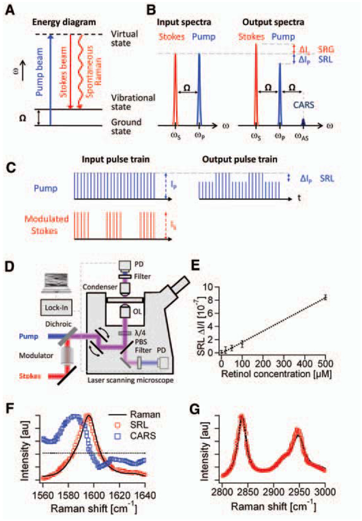
Here we explore stimulated Raman scattering (SRS) as an imaging contrast mechanism. SRS is analogous (5, 6) to the well-known phenomenon of stimulated emission (7) and was first observed in 1962 (8). It has been used in many spectroscopic studies (9–12). In spontaneous Raman scattering, only one laser beam at a frequency ωp illuminates the sample and the signal is generated at the Stokes and anti-Stokes frequencies, ωS and ωAS, respectively, due to inelastic scattering. In SRS, however, two laser beams at ωp and ωS coincide on the sample (Fig. 1A). When the difference frequency, Δω = ωp − ωS, also called the Raman shift, matches a particular molecular vibrational frequency Ω, amplification of the spontaneous Raman signal is achieved by virtue of stimulated excitation. Consequently, the intensity of the Stokes, IS, experiences a gain, ΔIS (stimulated Raman gain, SRG), and the intensity of the pump, Ip, experiences a loss, ΔIp (stimulated Raman loss, SRL), as shown in Fig. 1B. In contrast, when Δω does not match any vibrational resonance, SRL and SRG cannot occur. Therefore, unlike CARS, SRL and SRG do not exhibit a nonresonant background (11).
Fig. 1.
Principle and design of SRS microscopy. (A) Energy diagram for SRS. (B) Input and output spectra of SRS. SRS leads to an intensity increase in the Stokes beam (SRG) and an intensity decrease in the pump beam (SRL). Also shown (not to scale) is the CARS signal generated at the anti-Stokes frequency ωAS. (C) SRL detection scheme. Stokes beam is modulated at high frequency (MHz), at which the resulting amplitude modulation of the pump beam due to SRL can be detected. (D) SRL microscope with both forward and epi detection. The Stokes beam is modulated by an electro-optic modulator. The transmitted or reflected pump beam is filtered and detected by a large-area photodiode (PD). For epi detection, the backscattered beams are collected by the excitation objective lens (OL) and separated from the excitation beams by a combination of a quarter wave plate (λ/4) and polarizing beam splitter (PBS). The SRL is measured by a lock-in amplifier to provide a pixel of the image. Three-dimensional images are obtained by raster-scanning the laser focus across the sample, and microspectroscopy can be performed by automated tuning of the pump wavelength. (E) The linear dependence of SRL on concentrations of retinol in ethanol at 1595 cm−1. Modulation depth ΔIp/Ip < 10−7 can be achieved. Error bars show 1 SD of the signals for a 1-min recording. The detection limit was determined to be 50 µM. (F) Agreement of SRL spectrum (red circles) with the spontaneous Raman spectrum (black line) of the Raman peak (1595 cm−1) of 10 mM retinol in ethanol. The distorted CARS spectrum (blue squares) exhibits a typical dispersive shape. (G) The agreement of the more complex SRL spectrum of methanol (red circles) with the spontaneous Raman spectrum (black line).
The intensity of SRG or SRL is described by ΔIS ∝ N × σRaman × Ip × IS and ΔIp ∝ −N × σRaman × Ip× IS, where N is the number of molecules in the probe volume and σRaman is the molecular Raman scattering cross-section (6). As in other multiphoton techniques (3, 13), the nonlinearity of SRL and SRG in the overall excitation intensity allows three-dimensional (3D) sectioning. Such nonlinear excitation is typically accomplished by picosecond or femtosecond pulse trains in the near-infrared region.
SRS as a contrast mechanism for microscopy has been recently reported on the basis of multiplex detection with a photodiode array in combination with a femtosecond amplified laser system (14). Although the amplified laser system generates a large SRS signal, it is not suitable for bioimaging because the excessive peak power causes sample damage (15) and the low repetition rate limits the image acquisition speed.
We take a different approach, using high–repetition rate (76 MHz) picosecond pulse trains with four orders of magnitude lower peak power. The pump beam for SRL is provided by a synchronously pumped, tunable optical parametric oscillator (OPO), and the Stokes beam is provided by a 1064-nm mode-locked Nd:YVO4 oscillator. A 7-ps pulse width is chosen because its frequency bandwidth offers optimal spectral resolution (3 cm−1). Under this excitation condition, the small SRL and SRG signals (ΔIp/Ip and ΔIS/IS < 10−4) are buried in the laser noise. Realizing that laser noise occurs primarily at low frequencies, we implement a high-frequency phase-sensitive detection scheme (16, 17). For SRL, we modulate the intensity of the Stokes beam at 1.7 MHz and detect the resulting intensity modulation of the pump beam at the same frequency with a lock-in amplifier (Fig. 1C). Similarly, SRG can be measured by modulating the pump beam and detecting the Stokes beam (18). With this approach, ΔIp/Ip < 10−7 can be achieved with a 1-s time constant. To acquire images via beam scanning, we used a 300-µs time constant and a pixel dwell time of 170 µs. It is difficult to incorporate such phase-sensitive detection at radio frequency (MHz) with a multiplex detector such as a diode array, and our method is four orders of magnitude more sensitive than the previous report (14).
We detected SRL instead of SRG because the responsivity of the photodiode used is higher for the pump than for the Stokes beam. Collinear pump and Stokes beams are focused with a high–numerical aperture (NA) objective (NA = 1.2) onto a common focal spot (Fig. 1D). Because SRL and SRG are measured at the same frequencies as those of the input fields, phase matching is automatically fulfilled. This allows deconvolution with a point spread function similar to that of fluorescence microscopy and makes image interpretation simpler than in the case of CARS (19).
In SRL, the spatial resolution is limited by diffraction and is similar to that of two-photon fluorescence. To detect the pump or Stokes beams in the forward direction, we used a condenser with an NA = 1.35, which is higher than that of the excitation objective, to minimize unwanted background due to cross-phase modulation, which can yield spurious background (20, 21). Alternatively, backward (epi) detection is possible in turbid samples because multiple scattering events redirect a considerable portion of the forward-propagating pump and Stokes beams to the backward direction, which can be collected with the same excitation objective lens (22). SRL or SRG spectra at a particular position in the sample can be recorded by automated OPO tuning.
We verified that SRL is linear in both the pump and Stokes intensities (18). Unlike the CARS signal that is proportional to the square of the concentration, the linear dependence of SRL on analyte concentration (Fig. 1E) allows straightforward quantitative analysis. The detection limit is 50 µM for retinol solutions (Fig. 1E) and 5 mM for methanol (18), with average laser power <40 mW (30 MW/cm2) for each beam. Close to the shot noise limit, this sensitivity corresponds to about 3000 retinol and 300,000 methanol molecules in focus, respectively, which has surpassed the detection limit reported for CARS microscopy (23).
We show in Fig. 1F the SRL, spontaneous Raman, and CARS spectra of an isolated Raman peak of trans-retinol (18). Whereas SRL and spontaneous Raman spectra are nearly identical, the CARS spectrum exhibits a nonresonant background independent of the Raman shift, and spectral distortion because of interference with the background (24). Good agreement between the SRL, SRG, and spontaneous Raman spectra is also seen for spectra with multiple peaks (Fig. 1G) (18, 25). Thus, SRS allows simple spectroscopic identification based on the Raman literature, particularly in the “crowded” fingerprint region.
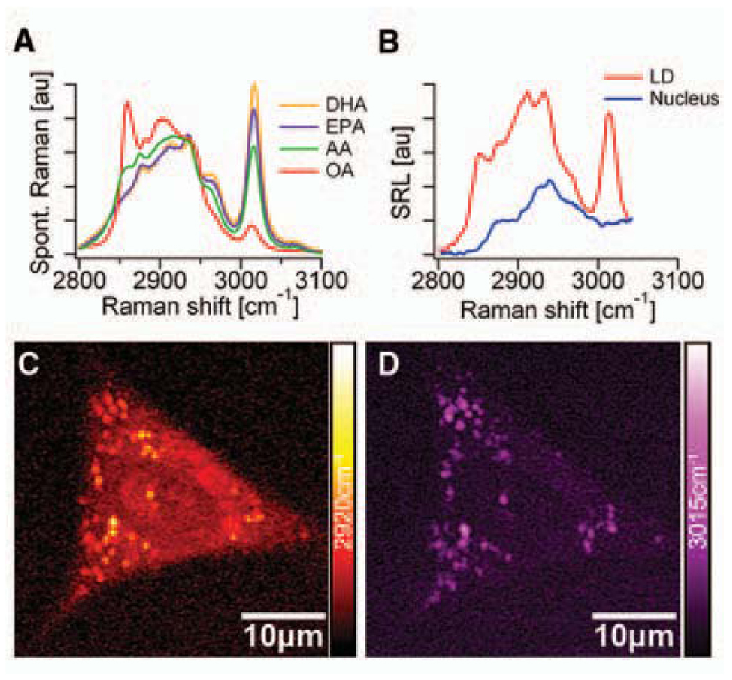
As the first application, we monitored the uptake of omega-3 fatty acids by living human lung cancer cells through SRL imaging and microspectroscopy (Fig. 2). Polyunsaturated omega-3 fatty acids, such as eicosapentaenoic acid (EPA), provide health benefits through mechanisms such as dampening inflammation, lowering blood triglyceride concentrations, and inducing cancer cell apoptosis, but can only be obtained from the diet (26). As shown in Fig. 2A, unsaturated fatty acids exhibit a Raman band at 3015 cm−1, attributable to the stretching mode of =C-H bond associated with C=C double bonds (27). The intensity of this 3015 cm−1 mode is approximately proportional to the number of C=C double bonds in the lipid molecule. In contrast, the 2920cm−1 peak intensity is found to be similar for all saturated and unsaturated fatty acids.
Fig. 2.
Omega-3 fatty acid uptake by A549 human lung-cancer cells monitored with SRL microscopy and microspectroscopy. (A) Spontaneous Raman spectra of docosahexaenoic acid (DHA, with six C=C bonds), eicosapentaenoic acid (EPA, with five C=C bonds), arachidonic acid (AA, with four C=C bonds), and oleic acid (OA, with a single C=C bond). The strong Raman peak around 3015 cm−1 is characteristic of unsaturated fatty acids. (B) SRL spectra of a lipid droplet (LD, red line) and a region inside the nucleus (blue line). Unlike the nuclear region, the SRL spectrum of the LD shows good correspondence with the spectra from the pure EPA shown in (A). (C) SRL image of a cell at 2920cm−1. (D) SRL image of the same cell at 3015 cm−1. These findings indicate that EPA is taken up by the cells and more strongly enriched in the LDs compared to other cellular organelles. No structural changes of the living cells due to photodamage were observed after repeated scans.
When cells are grown with 25 µM EPA for 24 hours (18), lipid droplets (LDs) are visible when imaging at both 2920 cm−1 (Fig. 2C) and 3015 cm−1 (Fig. 2D) bands. In the absence of EPA in the culturing media, the cells have few LDs inside the cytoplasm due to the limited lipid supply (18). The SRL images show a much stronger signal outside the LDs at 2920 cm−1 than at 3015 cm−1, indicating that most of the fatty acids in the cells are saturated. We also conducted SRL microspectroscopy at specific positions inside the cell to identify the local chemical composition. The nucleus exhibits an SRL spectrum (blue in Fig. 2B) similar to that of the saturated fatty acids, with negligible contribution at 3015 cm−1, whereas LDs have a pronounced 3015 cm−1 peak (red in Fig. 2B). No sign of photodamage, such as plasma membrane blebbing (15), was observed even after repeated imaging of the same cell. Therefore, we can use SRL spectral imaging and microspectroscopy to follow uptake of unsaturated fatty acids by living cells, opening possibilities to study lipid metabolism and its associated diseases.
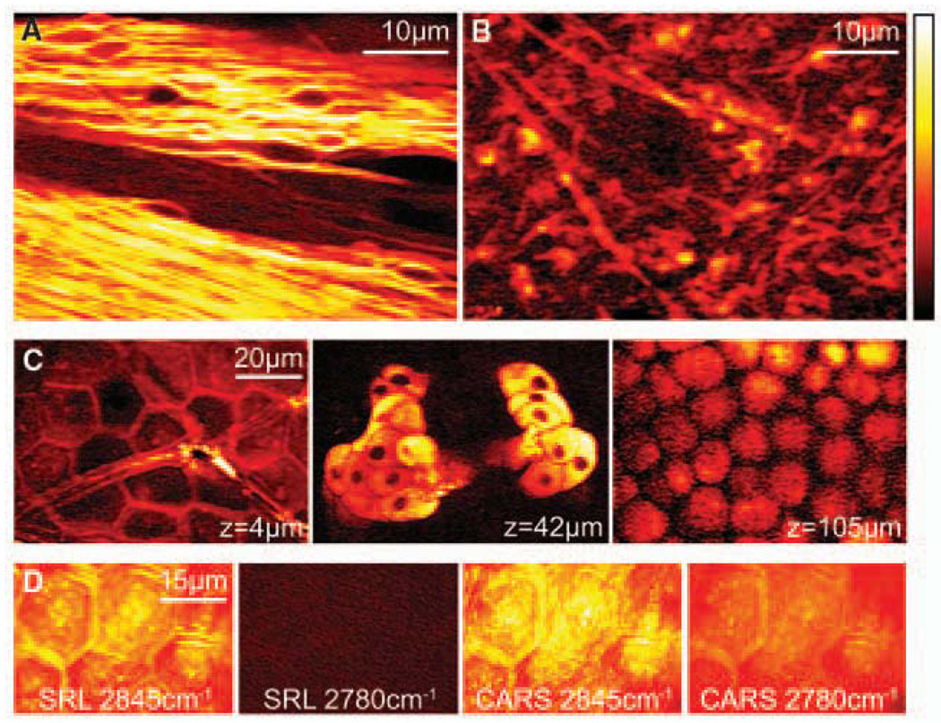
Next, we present SRS tissue imaging without staining. Many stains are impossible to apply in vivo. Label-free optical techniques, such as optical coherence tomography and diffusive optical tomography, often do not offer chemical contrast, while autofluorescence is limited to a few chemical species. A strong SRL signal originates from the CH2 stretching vibration (2845cm−1) of lipids in tissue, especially in the brain, where lipid-rich myelin sheaths surround axons, as was seen in CARS microscopy (28). Figure 3A shows forward-detected SRL images of a fiber tract in the corpus callosum of a thin slice of mouse brain. We also demonstrate epi SRL imaging from a ~1-mm-thick slice of mouse brain (Fig. 3B), which clearly reveals individual neurons.
Fig. 3.
SRL imaging of fresh mouse tissue. (A) Neuron bundles in corpus callosum of mouse brain imaged at 2845cm−1 highlighting myelin sheaths rich in CH2. (B) Epi-detected SRL CH2 image acquired from thick brain tissue. (C) SRL CH2 images of mouse ear skin in the same area at the indicated depths. From left to right: stratum corneum (4 µm), sebaceous gland (42 µm), and subcutaneous fat layer (105 µm). (D) Comparison of SRL and CARS images of stratum corneum on (2845 cm−1) and off (2780 cm−1) the CH2 resonance. Unlike CARS, SRL has no nonresonant background.
Skin imaging is another application of SRS microscopy. Figure 3C shows three individual SRL sections of mouse skin in the same area but at different depths, all with Δω tuned into 2845cm−1 (18). This highlights the 3D capability and subcellular resolution of SRS in tissue. At a depth of 4 µm, the SRL image shows the stratum corneum, which consists of polygonal cells and serves as the main protective layer of the body. This suggests that the intercellular space is rich in lipids. At a depth of 42 µm, lipid-rich sebaceous glands can be identified in the dermis. The nuclei of the gland cells are dark spots due to the lack of lipids. At a depth of 105 µm, the subcutaneous fat layer is clearly visible.
Figure 3D compares on and off vibrational resonance SRL and CARS images of stratum corneum. When Δω is tuned from on-resonance (2845 cm−1) to off-resonance (2780 cm−1) of the CH2 stretching mode, the SRL signal vanishes completely, whereas the nonresonant CARS background still exhibits contrast that complicates image interpretation. We note that tissue autofluorescence does not interfere with the SRS. The absence of the nonresonant background in SRS reflects the major advantage over CARS imaging.
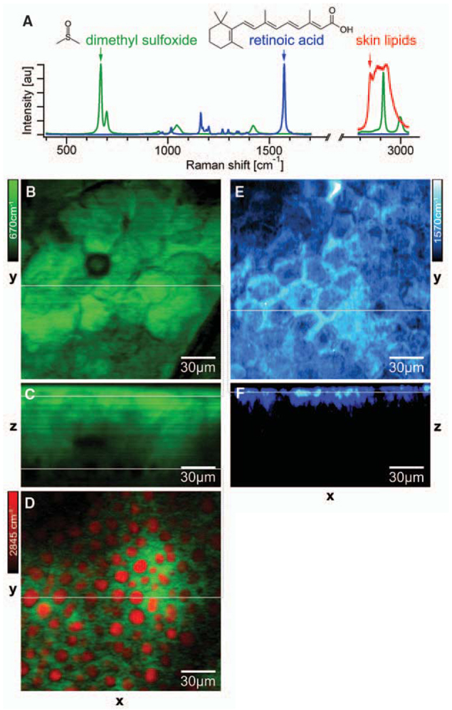
We also show the use of SRS to monitor drug delivery. Fluorescent labels are usually larger than drug molecules and may perturb their transport properties. Although confocal spontaneous Raman microspectroscopy has been used to obtain longitudinal penetration profiles, the lateral distribution is often compromised due to the long pixel dwell times (29). Here we show the mapping of the distribution of two compounds: dimethyl sulfoxide (DMSO), a skin-penetration enhancer (29); and retinoic acid (RA), which is used to treat acne, wrinkles, photo-aging, and acute promyelocytic leukemia (30). According to Raman spectra (Fig. 4A), DMSO and RA have isolated vibrational resonances at 670 and 1570 cm−1, respectively.
Fig. 4.
Monitoring drug delivery into fresh mouse skin by SRS microscopy. (A) Raman spectra of dimethyl sulfoxide (DMSO, green), retinoic acid (RA, blue), and typical lipids in mouse skin (red). (B) Top view of the penetrated DMSO (green) in the stratum corneum imaged at 670 cm−1 with SRL. (C) SRL DMSO depth profile through the line in (B). (D) Simultaneous two-color SRL image (18) of DMSO (670 cm−1, green) and lipid (2845 cm−1, red) in the subcutaneous fat layer at a depth of ~65 µm through the lower line in (C). (E) Top view of the penetrated RA (blue) in the stratum corneum imaged at 1570 cm−1 with SRL. (F) SRL RA depth profile through the line in (E). SRS allows label-free 3D in situ visualization of two different drug-delivery pathways into the skin.
As a hydrophilic molecule, DMSO penetrates the skin via the protein phase, so the DMSO image in the stratum corneum (Fig. 4B) shows inverse contrast compared to the lipid image in Fig. 3C. Adepth profile shows detectable DMSO over more than 60 µm (Fig. 4C), and the hydrophilic interaction with the tissue is confirmed in the subcutaneous fat layer. Simultaneous two-color imaging tuned into lipid and DMSO (18) allows us to show that the DMSO is insoluble in the lipid structures (Fig. 4D). In contrast, RA, which is a hydrophobic molecule, penetrates via the lipid-rich intercellular space in the epidermis (Fig. 4, E and F) after ultrasonication of the tissue to enhance delivery (18). These results show that SRS offers a new approach for studying pharmacokinetics in situ. As a label-free and sensitive imaging modality, SRS microscopy allows mapping of molecular species in 3D and the ability to follow their dynamics in living cells and organisms based on the wealth of Raman spectroscopy.
Supplementary Material
Footnotes
Supporting Online Material
www.sciencemag.org/cgi/content/full/VOL/ISSUE/PAGE/DC1
Materials and Methods
Figs. S1 to S6
Movies S1 to S3
References and Notes
- 1.Raman CV, Krishnan KS. Nature. 1928;121:711. [Google Scholar]
- 2.Turrell G, Corset J. Raman Microscopy: Developments and Applications. New York: Academic Press; 1996. [Google Scholar]
- 3.Zumbusch A, Holtom GR, Xie XS. Phys. Rev. Lett. 1999;82:4142. [Google Scholar]
- 4.Evans CL, Xie XS. Annu. Rev. Anal. Chem. 2008;1:27. doi: 10.1146/annurev.anchem.1.031207.112754. [DOI] [PubMed] [Google Scholar]
- 5.Bloembergen N. Am. J. Phys. 1967;35:989. [Google Scholar]
- 6.Boyd RW. Nonlinear Optics. New York: Academic Press; 2003. [Google Scholar]
- 7.Einstein A. Phys. Z. 1917;18:121. [Google Scholar]
- 8.Woodbury EJ, Ng WK. P IRE. 1962;50:2367. [Google Scholar]
- 9.Owyoung A. Opt. Commun. 1977;22:323. [Google Scholar]
- 10.Levine BF, Shank CV, Heritage JP. IEEE J. Quantum Electron. 1979;15:1418. [Google Scholar]
- 11.Levenson MD, Kano SS. Introduction to Nonlinear Laser Spectroscopy. New York: Academic Press; 1988. [Google Scholar]
- 12.Kukura P, McCamant DW, Mathies RA. Annu. Rev. Phys. Chem. 2007;58:461. doi: 10.1146/annurev.physchem.58.032806.104456. [DOI] [PubMed] [Google Scholar]
- 13.Denk W, Strickler JH, Webb WW. Science. 1990;248:73. doi: 10.1126/science.2321027. [DOI] [PubMed] [Google Scholar]
- 14.Ploetz E, Laimgruber S, Berner S, Zinth W, Gilch P. Appl. Phys. B Lasers Opt. 2007;87:389. [Google Scholar]
- 15.Fu Y, Wang HF, Shi RY, Cheng JX. Opt. Exp. 2006;14:3942. doi: 10.1364/oe.14.003942. [DOI] [PubMed] [Google Scholar]
- 16.Ye J, Ma LS, Hall JL. J. Opt. Soc. Am. B. 1998;15:6. [Google Scholar]
- 17.Fu D, et al. Opt. Lett. 2007;32:2641. doi: 10.1364/ol.32.002641. [DOI] [PubMed] [Google Scholar]
- 18.Methods, additional results, and movies are available as supporting material on Science Online
- 19.Potma EO, de Boeij WP, Wiersma DA. J. Opt. Soc. Am. B. 2000;17:1678. [Google Scholar]
- 20.Ekvall K, et al. J. Appl. Phys. 2000;87:2340. [Google Scholar]
- 21.Another spurious background signal can arise from two-color two-photon absorption of the pump and Stokes beams. See (17).
- 22.Evans CL, et al. Proc. Natl. Acad. Sci. U.S.A. 2005;102:16807. doi: 10.1073/pnas.0508282102. [DOI] [PMC free article] [PubMed] [Google Scholar]
- 23.Ganikhanov F, Evans CL, Saar BG, Xie XS. Opt. Lett. 2006;31:1872. doi: 10.1364/ol.31.001872. [DOI] [PubMed] [Google Scholar]
- 24.Shen YR. The Principle of Nonlinear Optics. New York: Wiley; 1984. [Google Scholar]
- 25.Subtle spectral differences between spontaneous Raman spectroscopy and SRS have been predicted theoretically. See (31).
- 26.Kang JX. J. Membr. Biol. 2005;206:165. doi: 10.1007/s00232-005-0790-3. [DOI] [PubMed] [Google Scholar]
- 27.Heinrich C, et al. Opt. Exp. 2008;16:2699. doi: 10.1364/oe.16.002699. [DOI] [PubMed] [Google Scholar]
- 28.Wang H, Fu Y, Zickmund P, Shi RY, Cheng JX. Biophys. J. 2005;89:581. doi: 10.1529/biophysj.105.061911. [DOI] [PMC free article] [PubMed] [Google Scholar]
- 29.Caspers PJ, et al. Pharm. Res. 2002;19:1577. doi: 10.1023/a:1020481305420. [DOI] [PubMed] [Google Scholar]
- 30.Van De Kerkhof PCM, et al. J. Dermatolog. Treat. 2006;17:198. doi: 10.1080/09546630600830596. [DOI] [PubMed] [Google Scholar]
- 31.Kukura P, McCamant DW, Mathies RA. J. Phys. Chem. A. 2004;108:5921. doi: 10.1021/jp0482971. [DOI] [PMC free article] [PubMed] [Google Scholar]
- 32.We thank C. Ackermann and S. Zhang for advice on skin imaging; S. Kesari for providing mouse tissue; J. Grice and M. Roberts for the loan of a sonicator; and G. Young, X. Xu, M. Rückel, and P. Sims for helpful discussions. C.W.F. and B.G.S. thank Boehringer Ingelheim Fonds for a Ph.D. Fellowship and the Army Research Office for an NDSEG fellowship, respectively. J.X.K. acknowledges support from the NIH (grant CA113605). The Xie Group is grateful to the U.S. Department of Energy’s Basic Energy Sciences program (DE-FG02-07ER15875) for supporting high-sensitivity Raman detection. The instrumentation development was supported by NSF (grant DBI-0649892), NIH Director’s Pioneer Award (to X.S.X.), Gates Foundation, and Pfizer Global Medical. Harvard University has filed a patent application based on this work.
Associated Data
This section collects any data citations, data availability statements, or supplementary materials included in this article.


