Summary
In this study, we present our experiences of personal computer-based 3D reconstructions of MRA for pre-treatment planning and post-treatment follow-up for cerebral aneurysms. Twenty-nine ruptured or unruptured intracranial aneurysm patients with 36 intracranial aneurysms, who underwent embolization and pretreatment and/or follow up 3D MRA were included in this study. All 29 patients were examined by DSA and MRA before (18 patients, 24 aneurysms) and/or after embolization (16 patients, 17 aneurysms). The MRA source images were transported to a personal computer in DICOM format for viewing, post-processing, and 3D reconstruction. DSA and PC based SSD 3D MRA equally well demonstrated most aneurysms before embolization (17 patients, 22 aneurysms). The depiction of aneurysm morphology, neck evaluation and branch vessel interpretation were much easier on 3D MRA, which has the ability to manipulate images in real time. When the vascular anatomy was complicated by another vascular system, the anterior or posterior circulations were separately reconstructed easily by using PC based reconstruction software. The 3D MRA also well demonstrated post-embolization recurrence or remnant aneurysmal cavities. In one giant aneurysm, the 3D MRA was unable to show the entire aneurysmal sac due to a blood flow saturation effect, but this was resolved by additional contrast material injection. PC-based 3D MRA proved to be a useful tool for the pretreatment planning of embolization procedures and for follow up after treatment in the case of cerebral aneurysms.
Key words: intracranial aneurysm, embolization, MR angiography, 3D software
Introduction
The detachable coil system including Guglielmi detachable coil (GDC) is now widely used for the treatment of intracranial aneurysms, and the number of centers in which detachable platinum coils are used to achieve aneurysmal occlusion is constantly increasing. Conventional angiography is an accepted protocol for the pretreatment planning and follow up of patients with cerebral aneurysms treated by coil embolization1-3, and the number of patients admitted for repeated intra-arterial digital subtraction angiography (IA DSA) is also increasing. Conventional angiography is invasive and carries a 1% complication risk and a 0.5% risk of persistent neurological deficit4. The substitution of magnetic resonance angiography (MRA) may offer a noninvasive or minimally invasive alternative to conventional angiography, which may result in less patient discomfort, morbidity and greater cost savings 5,6. The ability of MRA to screen for untreated aneurysms is fairly well documented 7,8, and three-dimensional time of flight (3D-TOF) MRA is now readily accepted as a noninvasive screening tool for aneurysmal disease 9,10. In terms of safety and image quality· MRA has also been found to be compatible with the presence of platinum coils11.
Recently· several PC-based software packages have been developed to reconstruct medical images from computed tomography (CT)· magnetic resonance imaging (MRI) and other medical units into real time three dimensional medical models and other image formats such as multiplanar reconstruction (MPR), maximum intensity projection (MIP)· volume rendering (VR) and oblique images. During the last two years· we have worked on assessing intracranial aneurysms before and/or after coil embolization by using a PC based 3D reconstruction of MRA· which allowed us to visualize aneurysms at any angle at our own desktop in real-time and to discuss with our neurosurgical co-workers in a network environment at any time. Many studies have been conducted on the value of MR workstation reconstructions· but to our knowledge no studies havebeen undertaken on the value of MRA reconstruction by universally used PC-based programs. In this study, we present our experiences of the use of PC-based real time 3D-TOF MRA for the pre-treatment planning of intracranial aneurysms and post-treatment follow up, and compared the results obtained with those of conventional DSA.
Material and Methods
Twenty-nine ruptured or unruptured intracranial aneurysm patients (23 females and six males of average age 56 years) with 36 intracranial aneurysms (18 distal ICA aneurysms, four posterior communicating artery aneurysms, four anterior communicating artery aneurysms, six middle cerebral artery aneurysms, and four posterior circulation aneurysms), who underwent embolization using detachable platinum coils and pretreatment and/or follow up PC based 3D MRA were included in this study. These patients presented with either subarachnoid hemorrhage (SAH) (n=20) or symptoms related to mass effect (n=9). Incidentally found asymptomatic aneurysms were also included in this study (n=7). All 29 patients were examined by IA DSA and 3D MRA before and/or after embolization. The pre-treatment 3D MRA were performed in 18 patients with 24 intracranial aneurysms. The interval between pre-treatment 3D MRA and conventional IA DSA was less than one week. Seventeen follow-up 3D MRAs were performed in 16 patients with 17 intracranial aneurysms. The interval between embolization and follow-up MRA varied from one week to two years (mean = 6.8 months).
All of the IA DSA studies were performed on an Integris V3000 angiographic unit (Philips, The Netherlands) with a 1024 × 1024 matrix. All patients were evaluated by conventional three or four-vessel angiography and additional angled projection angiography for detailed aneurismal assessment.
MRA examinations were performed on a Signa 1.5 T MRI unit (General Electric, Milwaukee, USA) or a Magnetom vision 1.5T MRI unit (Siemens, Erlangen, Germany) using a head coil. The MRA were obtained using the three-dimensional Time of flight (3D-TOF) MR angiographic technique. The imaging parameters used were TR 35, TE 7.2, flip angle 20, section thickness 1 mm or 1,5 mm, FOV 210 × 210, Matrix 200 × 512. Routine 3D-TOF MRA was performed without contrast enhancement but in two patients additional post contrast enhancement 3D TOF MRA images were obtained.
The MRA source images were transported to personal computer in Digital Image Communication in Medicine (DICOM) format for viewing and post-processing, and were then reconstructed using image processing software, V-works TM 3.5 (Cybermed Inc. Seoul, Korea).
In order to ensure reproducibility, visualization of the MR data was assessed by an experienced neuroradiologist with considerable experience of image post-processing. 3D-TOF MRA source images were reconstructed to three-dimensional shaded surface display (3D-SSD) images. Generation of whole 3D-SSD images was completed in about one minute. To obtain consistent results, threshold levels were determined using original axial images for reference to ensure against under- or over-representation of vessel lumen.
The reconstructed SSD images were rendered at any angle on our desktop PC, reviewed and compared with conventional angiograms in a non-blinded fashion by two experienced neuroradiologists.
We reviewed the DSA and the 3D reconstructed MRA images with respect to morphology of the aneurysmal sac, neck depiction, and the relationship with the connected vessels. The neck to fundus ratio of the aneurysm on DSA and 3D MRA were also comparatively evaluated in 17 patients with 22 aneurysms, who performed DSA and MRA before embolization. In one patient who performed both DSA and MRA before embolization, the neck to fundus ratio could not measured because the 3D MRA could not demonstrate the exact aneurismal neck. The neck to fundus ratio on DSA and 3D MRA were statistically compared using the Wilcoxon Rank Sum test.
Results
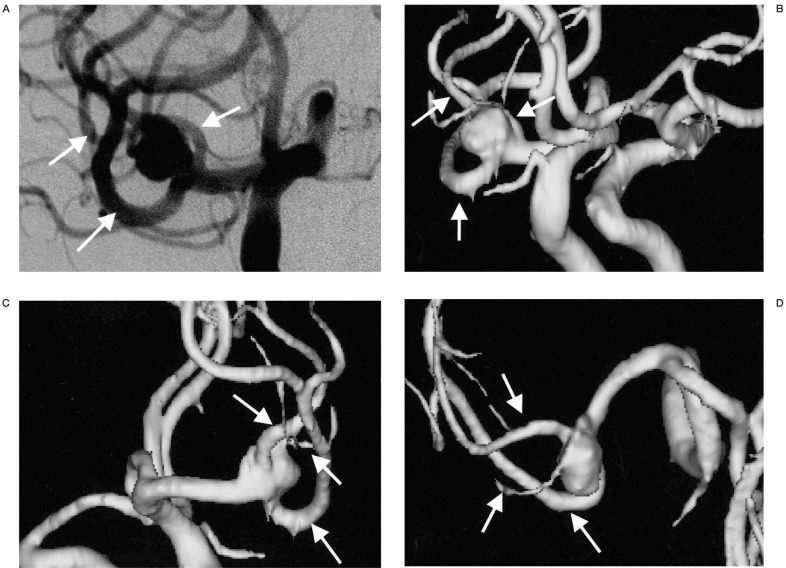
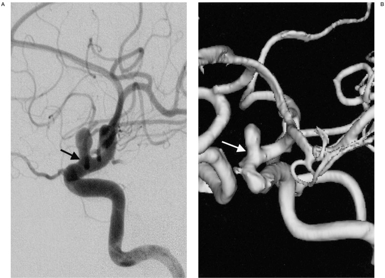
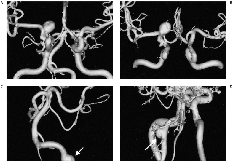
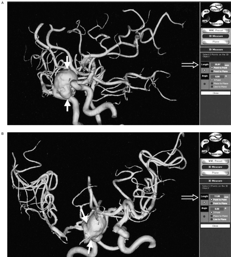
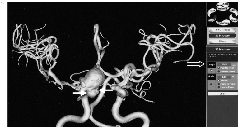
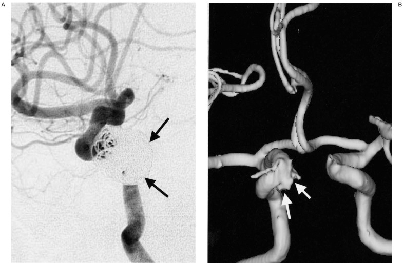
In 18 patients with 24 aneurysms, and in whom both pretreatment MRA and DSA were available, most aneurysms (22 aneurysms, 17 patients) were displayed well by both techniques. The exact aneurysm shape, the shape of the aneurismal neck and the relationship with connected vessels were easily demonstrated on 3D-SSD MRA, because the aneurysms were three-dimensionally visualized from any arbitrary direction on our own desktop monitor in real time (figure 1). However, in most of the aneurysms (n=16, 12 patients), the aneurismal neck was slightly broader on the 3D reconstructed SSD MRA than on DSA (figure 2), and the neck to fundus ratio measured on DSA and 3D MRA were significantly different (p < 0.05) by the Wilcoxon rank sum test. When the vascular anatomy was complicated by the presence of another vascular system, the anterior and posterior circulations and right and left internal carotid arteries were easily and separately reconstructed by the V-works program (figure 3). Using the PC-based 3D MRA reconstruction program, we were able to measure any part of the aneurysm, for example, its length, daughter sac size or neck size, which could not be done on DSA (figure 4).
Figure 1.
An aneurysm located at the right middle cerebral artery trifurcation. A) The aneurysm is viewed at right oblique projection on DSA. B-D) On 3D MRA, the aneurysm is viewed at multiple projections on the PC monitor. The relationships between the aneurysm and trifurcating MCA branches (arrows) are more easily demonstrable on the 3D MRA compared with on the DSA image (A) because aneurysm and each arterial branch can be observed at any arbitrary angles.
Figure 2.
A distal ICA aneurysm on DSA and MRA. A) A distal ICA aneurysm is seen on DSA by right ICA injection. B) On 3D surface rendering reconstructed MRA, the aneurysmal neck (arrow) is slightly broader than that on DSA (arrow).
Figure 3.
The separate reconstruction of anterior and posterior circulation. A) A 3D-SSD MRA shows both anterior and posterior circulations. B) A 3D-MRA reconstruction shows anterior circulation only by selective segmentation and reconstruction. C) A 3D-reconstructed MRA only shows the posterior circulation only by selective segmentation and reconstruction. D) A 3D reconstructed MRA image at lower level scan shows another aneurysmal sac in the vertebral artery. When the vascular anatomy was complicated by another vascular system (A), the anterior (B) and posterior circulations (C,D) could be easily separately reconstructed by PC based software. In this ICA aneurysm and anterior circulation are more clearly demonstrable by removal of the posterior circulation. The vertebral artery aneurysm (arrow, C) was re-evaluated by another scan at lower level (D).
Figure 4.
Size measurement. A) The long diameter of multilobulated distal ICA aneurysm is measured on 3D MRA (solid arrows) and the value is displayed on the screen (open arrow). B) The size of aneurysmal neck is directly measured on 3D MRA (solid arrows) and the value is displayed on the screen (open arrow). C) The size of the daughter sac is measured on 3D MRA (solid arrows). On PC based 3D MRA reconstruction images, the direct measurements of any part of the aneurysm sac were possible, which could not be done on DSA.
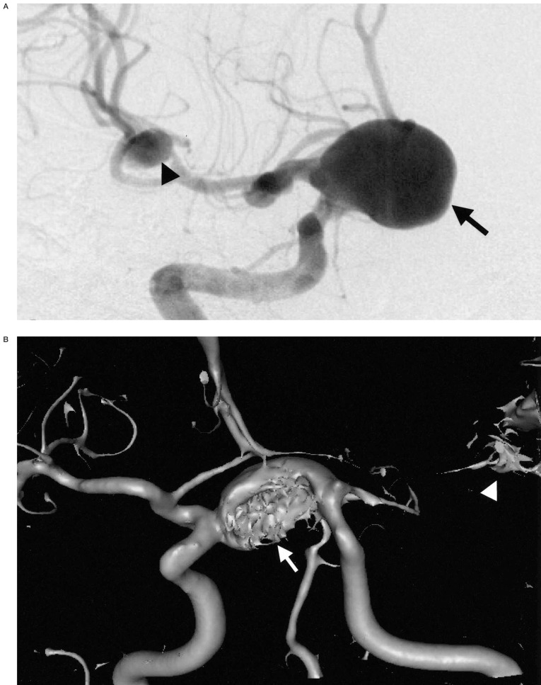
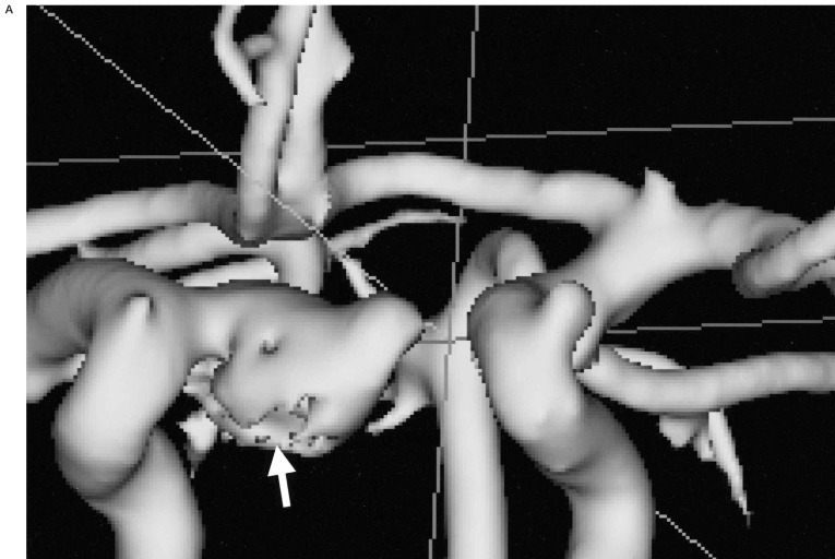
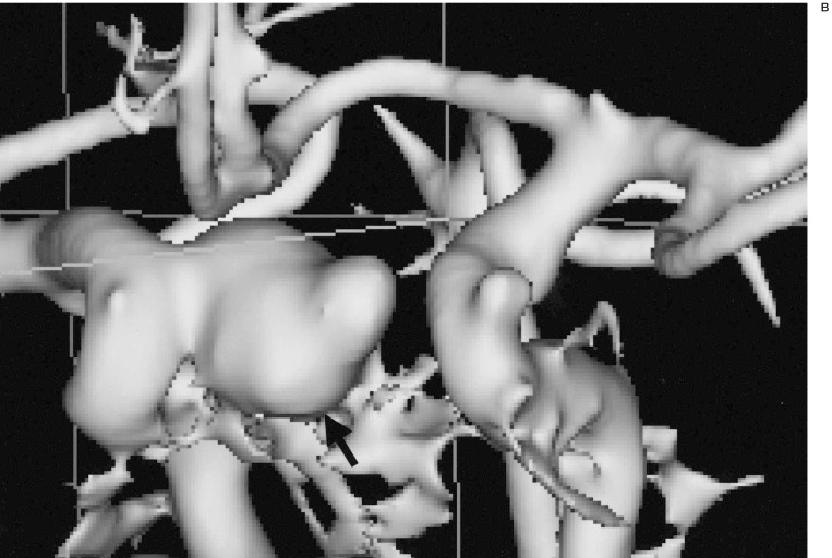
In the case of one giant aneurysm, the 3D MR angiographic reconstruction images could not demonstrate the entire aneurysmal sac, which was seen on DSA images, and which seemed to result from a blood flow saturation effect due to slow and turbulent flow within the aneurysm (figure 5). However, in another case, the saturation effect was resolved by contrast enhancement (figure 6).
Figure 5.
Blood flow saturation effect on 3D MRA. A) A giant aneurysm (arrow) in distal ICA and another small aneurysm in the right MCA trifurcation (arrowhead) are demonstrated on DSA. B) The 3D-SSD MRA does not show the entire ICA aneurysmal sac (arrow) because of flow saturation effect of turbulent flow. The right MCA aneurysm (arrowhead) is also not seen, and this is thought to be the result of a blood flow saturation effect.
Figure 6.
3D MRA after contrast material injection. A) 3D MRA image without contrast enhancement shows the irregularity (arrow) of the aneurysmal sac probably due to blood flow saturation effect in the inferior part. B) The filling defect of the ICA aneurysmal sac is disappeared on the 3D MR angiography with additional contrast enhancement scan (arrow).
In patients with follow up 3D MRA, occlusion of the aneurysms with detachable coils during the procedures was achieved in a range from 70% to 100%. On 17 follow up 3D MR angiograms of 17 aneurysms in 16 patients· six remnant cavities were detected· which were thought to be caused by coil packing or partial embolization. The size of these remnant cavities varied from 1 mm to 2,5 mm. However, because simultaneous DSA was not performed· we could not evaluate the true positive rate or the exaggeration or underestimation of remnant cavity size (figure 7).
Figure 7.
3D MRA follow up of aneurysm treated with GDCs. A) The distal ICA aneurysm is near-completely occluded by GDCs on post embolization DSA. B) One year follow up 3D MRA shows the remnant cavity (arrows) in the aneurysm probably caused by compact modification of the coils.
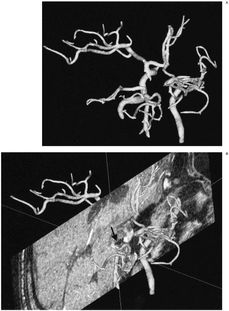
Background sectional images could be assembled in the reconstructed 3D MRA vascular images, which allowed for the assessment of the spatial relationship between and aneurysm and its surrounding structures (figure 8).
Figure 8.
Background multiplanar MR image assembly. A) A posterior superior view of reconstructed 3D MRA image in a patient with basilar top aneurysm treated by coils one year before. B) 3D MRA image is assembled with the background reconstructed coronal MR image at the level of the basilar top. Previously embolized coil mass is seen as a small area of low signal intensity (arrow) at the top of the basilar artery
Discussion
There have been many reports on the diagnostic value of MRA for the detection and characterization of intracranial aneurysms8-10,12-15.
However, the majority of studies have been undertaken on the MR workstation. Recently, many software packages have become available for the reconstruction of medical images from CT or MR. These can be used on desktop PCs and are usually cheap compared with the reconstruction programs for MR workstations. Articles that have reported upon the usefulness of 3D MRA generally evaluated software for MR workstations 8,12-15. However, the software we used is compatible with normal PCs, and can manipulate images at any time and place, and importantly, it is capable of network environments at any time.
Using our PC based MRA reconstruction program, MIP reconstruction or virtual endoscopy and SSD reconstruction of MRA were all possible, although we used the SSD technique for image post-processing in this study. In articles that evaluated 3D reconstructions of MRA, most investigators have relied on the MIP method for post-processing8,13,15. Adams et Al evaluated multiple 3D TOF MRA reconstruction techniques for the pretreatment assessment of cerebral aneurysms in a comparative study involving MPR MRA, MIP MRA, isosurface rendering MRA, MR source images and intra-arterial digital subtraction angiography (IA-DSA)12. In their study, they reported that MIP-MRA was poor compared with other 3D MRA techniques and IA-DSA in terms of the depiction of aneurysm morphology as well as neck and branch vessel definition. They suggested that low signal intensity regions of a vessel may appear as “streamlining”, or worse still may disappear completely on MIP images16. Moreover, because the MIP gray scale is derived from the composite value of all the pixels along an imaging plane, smaller structures, such as small aneurysms (less than 2 mm) may be assigned inappropriately low signal intensities and disappear on MIP-MRA12. On the other hand, they stated that the 3D-isosurface rendering MRA was comparable with IA-DSA in the depiction of aneurysm morphology, neck and branch vessel definition. In addition, they added that the ability to manipulate an image in real time, the spatial awareness produced by the shade surface rendering, and the selective targeting that was required to remove overlying vessels contributed to these results 12. In our study, the benefits of SSD MRA were similar to those found by Adams. However, in our study, 3D SSD MRA showed larger neck to fundus ratios than IA-DSA. In SSD reconstruction, the threshold set is extremely important because inappropriate thresholding may cause an over or underestimation of neck size, which makes an aneurysm unfavorable or favorable for coil embolization. For adequate thresholding, meticulous analysis of the source image data should be performed before establishing the threshold set for 3D SSA MRA.
Direct size measurement is an important benefit of PC based MRA reconstruction, and cannot be done on DSA, because adequate size determination is required for pretreatment planning for coil embolization of intracranial aneurysms. A few authors have reported on the diagnostic value of MRA for the follow up ofintracranial aneurysms treated by using detachable coils17-20. In these studies, 3D MRA showed sensitivities varying from 75% to 90% and specificities from 90% to 100% in the detection of residual aneurysms 17-20. Moreover, in these studies, MIP was used for post processing. In the present study, six remnant cavities, with dimensions from 1 mm to 2,5 mm, were detected on the follow up 3D-SSD MRA. Because we did not perform coincident IA-DSA, we could not gain a true positive detection rate of remnant cavity by 3D-SSD MRA using PC based software, but the results suggest that the PC based 3D-SSD MRA may be a substitute for IA-DSA for the follow up aneurysms treated by detachable platinum coils.
In one of our cases, the 3D-SSD MRA could not demonstrate the entire aneurysm sac, probably due to the MR saturation effect originating from turbulent blood flow within the aneurysmal sac (figure 5). The saturation effect was resolved by contrast enhancement in another case (figure 6). Slow and turbulent flow in giant aneurysms leads to flow saturation and phase dispersion, which often precludes complete delineation on 3D-TOF studies 21-23. However, additional contrast enhanced 3D-TOF MRA reliably shows the aneurysm sac and the connected vessels24. Moreover, when a giant aneurysm is encountered that cannot be shown entirely on precontrast 3D-TOF MRA, the entire aneurysmal sac be visualized by additional contrast enhanced scan.
Conclusions
The PC-based 3D-SSD reconstruction of TOF MRA may be a useful tool for the pretreatment planning for detachable coil embolization of intracranial aneurysms and for follow up after treatment, but the cautious thresholding is required before post-processing to adequately evaluate the aneurysmal neck.
References
- 1.Vinuela F, Duckwiler G, Mawad M. Gugliemi detachable coil embolization of acute intracranial aneurysms: perioperative anatomical and clinical outcome in 403 patients. J Neurosurg. 1997;86:475–482. doi: 10.3171/jns.1997.86.3.0475. [DOI] [PubMed] [Google Scholar]
- 2.Vanninen R, Koivisto T, et al. Ruptured intracranial aneurysms: acute endovascular treatment with electrolytically detachable coils: a prospective randomized study. Radiology. 1999;211:325–336. doi: 10.1148/radiology.211.2.r99ap06325. [DOI] [PubMed] [Google Scholar]
- 3.Kuether TA, Nesbit GM, Barnwell SL. Clinical and angiographic outcomes, with treatment data, for patients with cerebral aneurysms treated with Gugliemi detachable coils: a single-center experience. Neurosurgery. 1998;43:1016–1025. doi: 10.1097/00006123-199811000-00007. [DOI] [PubMed] [Google Scholar]
- 4.Heiserman JE, Dean BL, et al. Neurologic complication of cerebral angiography. Am J Neuroradiol. 1994;15:1401–1407. [PMC free article] [PubMed] [Google Scholar]
- 5.Swan JS, Fryback DB, et al. MR and conventional angiography: work in progress toward assessing utility in radiology. Acad Radiol. 1997;4:475–482. doi: 10.1016/s1076-6332(97)80231-0. [DOI] [PubMed] [Google Scholar]
- 6.Swan JS, Langlotz CP. Patient preference for magnetic resonance versus conventional angiography: assessment methods and implication for cost effectiveness analysis, an overview. Invest Radiol. 1998;33:553–559. doi: 10.1097/00004424-199809000-00011. [DOI] [PubMed] [Google Scholar]
- 7.Schuierer G, Huk WJ, Laub G. Magnetic resonance angiography of intracranial aneurysms: comparison with intra-arterial digital subraction angiography. Neuroradiology. 1992;35:50–54. doi: 10.1007/BF00588279. [DOI] [PubMed] [Google Scholar]
- 8.Atlas SW, Sheppard L, et al. Intracranial aneurysms: detection and characterization with MR angiography with use of an advanced postprocessing technique in a blinded-reader study. Radiology. 1997;203:807–814. doi: 10.1148/radiology.203.3.9169709. [DOI] [PubMed] [Google Scholar]
- 9.Ronkainen A, Puranen MI, et al. Intracranial aneurysms: MR angiography screening in 400 asymptomatic individuals with increased familial risk. Radiology. 1995;195:35–40. doi: 10.1148/radiology.195.1.7892491. [DOI] [PubMed] [Google Scholar]
- 10.Litt AW. Commentary. MR angiography of intracranial aneurysms: proceed, but with caution. Am J Neuroradiol. 1994;15:1615–1616. [PMC free article] [PubMed] [Google Scholar]
- 11.Hartman J, Nguyen T, et al. MR artifacts, heat production, and ferromagnetism of Gugliemi detachable coils. Am J Neuroradiol. 1996;18:279–286. [PMC free article] [PubMed] [Google Scholar]
- 12.Adams SM, Laitt RD, Jackson A. The role of MR angiography in the pretreatment assessment of intracranial aneurysms: a comparative study. Am J Neuroradiol. 2000;21:1618–1628. [PMC free article] [PubMed] [Google Scholar]
- 13.Grandin CB, Mathurin P, et al. Diagnosis of intracranial aneurysms: accuracy of MR angiography at 0.5T. Am J Neuroradiol. 1998;19:245–252. [PMC free article] [PubMed] [Google Scholar]
- 14.Rubinstein D, Sandberg EJ, et al. T2-weighted tree-dimensional turbo spin-echo MR of intracranial aneurysms. Am J Neuroradiol. 1997;18:1939–1943. [PMC free article] [PubMed] [Google Scholar]
- 15.Ida M, Kurisu Y, Yamashita M. MR angiography of ruptured aneurysms in acute subarchnoid hemorrhage. Am J Meuroradiol. 1997;18:1025–1032. [PMC free article] [PubMed] [Google Scholar]
- 16.Korohi Y, Takahashi M, et al. Intracranial vascular stenosis and occlusion: MR angiographic findings. Am J Neuroradiol. 1997;18:135–143. [PMC free article] [PubMed] [Google Scholar]
- 17.Kahara VJ, Seppänen SK, et al. MR angiography with three-dimensional time of flight and targeted maximum intensity projection reconstructions in the follow up of intracranial aneurysms embolized with Guglielmi detachable coils. Am J Neuroradiol. 1999;20:1470–1475. [PMC free article] [PubMed] [Google Scholar]
- 18.Brunereau L, Cottier JP, et al. Prospective evaluation of time of flight MR angiography in the follow up of intracranial saccular aneurysms treated with Guglielmi detachable coils. JCAT J Comput assist Tomogr. 1993;23:216–222. doi: 10.1097/00004728-199903000-00009. [DOI] [PubMed] [Google Scholar]
- 19.Michardiere R, Bebsalem D, et al. Comparison or MRA and angiography in the follow-up of intracranial aneurysms treated with GDC. Report of 25 correlations. J Neuroradiol. 2001;28:75–83. [PubMed] [Google Scholar]
- 20.Weber W, Yousry TA, et al. Noninvasive follow-up of GDC-treated saccular aneurysms by MR angiography. Eur Radiol. 2001;11:1792–1797. doi: 10.1007/s003300000741. [DOI] [PubMed] [Google Scholar]
- 21.Ross JS, Masaryk TJ, et al. Intracranial aneurysms: evaluation by MR angiography. Am J Neuroradiol. 1990;155:449–456. [PMC free article] [PubMed] [Google Scholar]
- 22.Schuierer G, Huk WJ, Laub G. Magnetic resonance angiography of intracranial aneurysms: comparison with intra-arterial digital subtraction angiography. Neuroradiology. 1992;35:50–54. doi: 10.1007/BF00588279. [DOI] [PubMed] [Google Scholar]
- 23.Brugières P, Blustajn J, et al. Magnetic resonance angiography of giant intracranial aneurysms. Neuroradiology. 1998;40:96–102. doi: 10.1007/s002340050547. [DOI] [PubMed] [Google Scholar]
- 24.Jäger HR, Ellamushi H, et al. Contrast-enhanced MR angiography of intracranial giant aneurysms. Am J Neuroradiol. 2000;21:1900–1907. [PMC free article] [PubMed] [Google Scholar]


