Abstract
Background:
The purpose of this study was to determine flap parameter accuracy, extent of the opaque bubble layer, and incidence of skip lines in femtosecond laser-assisted stromal in situ keratomileusis (LASIK) using the WaveLight® FS200 laser and optoelectronic clinical measurements.
Methods:
Images from 101 flaps were automatically recorded during consecutive routine LASIK procedures performed using the WaveLight FS200 femtosecond laser and the EX500 excimer laser. Digital processing of these images was used to evaluate objectively the diameter of FS200-created flaps, by comparing planned versus achieved procedures and to evaluate the incidence and extent (area) of the opaque bubble layer.
Results:
The intended flap diameters were between 8.00 mm and 9.50 mm. The achieved flap diameters showed extremely high precision, and were on average −0.16 ± 0.04 mm smaller for a 8.00 mm intended flap diameter, −0.12 ± 0.03 mm smaller for a 8.50 mm flap, and up +0.06 ± 0.06 mm wider for a 9.50 mm flap. With an average flap area of 72.4 mm2, the mean area of the opaque bubble layer (4.1 ± 4.3 [range 0–14.34] mm2) corresponded to a 6% opaque bubble layer-to-flap area. Specifically, 80% of the femtosecond-created flaps had an essentially zero opaque bubble layer (<2.7% of the flap area).
Conclusion:
In our clinical experience, flaps created using FS200 and this novel highly objective assessment technique demonstrate both precision and reproducibility. The incidence of opaque bubble layer was minimal.
Keywords: femtosecond laser precision, bladeless laser-assisted stromal in situ keratomileusis, corneal flap diameter, opaque bubble layer, skip lines, WaveLight FS200
Video abstract
Introduction
There has been almost a decade of continuous improvement since the introduction of the near-infrared Nd:glass ultrashort pulse (100 × 10−15 second) laser, known as the femtosecond, as a tool for creating flaps for the laser-assisted stromal in situ keratomileusis (LASIK) procedure.1 The laser light, due to its near-infrared wavelength (1.053 μm), has little interaction with the corneal surface (unlike the ultraviolet wavelength of excimer lasers), and thus can propagate through the corneal tissue. However, the concentrated energy per pulse when properly focused inside the corneal stroma can generate local ablation and a small amount of microplasma, which results in microscopic cavitation and gas bubbles; proper arrangement in a raster form of a large number of tightly spaced (eg, less than 8 μm apart) consecutive bubbles is the principle of femtosecond laser flap creation.2,3
Control of the corneal depth in which the beam is designed to come into focus (customizable in a specific laser up to 1000 μm), as well as control of the x–y location of the target foci is of utmost importance for successful flap creation. For this reason, the cornea is flattened (applanation) prior to flap creation using a suction-applanation cone lens to immobilize the eye and allow control of the femtosecond laser beam focus inside the stroma.4
Five generations of femtosecond lasers for refractive surgery have been introduced so far, and while the “perfect” LASIK flap is becoming more and more tangible, there are still issues that need further study. Predictability of flap cutting parameters, including the precision and accuracy of flap size (diameter) and thickness is an important consideration, and there appears to be consensus in the literature that femtosecond-created flaps are superior to microkeratome-created flaps.5,6 The incidence of opaque bubble layer (OBL) as well as skip lines is another issue.
While the fundamental physics of lamellar femtosecond laser-created tissue separation has not changed, there is significant ongoing development of computerized laser steering methods aiming at obtaining repeatable, accurate, and precise corneal flap cutting. For example, the pulse rate frequency (not to be confused with laser photon frequency, determined by active lasing medium) has been increased from 10–15 kHz to up to 200 kHz over the last decade. This has allowed a substantial increase in the rate of successive micropulse-driven ablations, finer ablation bubble patterns, and thus a reduced total time for flap creation and increased flap quality. In addition, increased precision and accuracy has enabled routine creation of thin (eg, 90 μm) and small myopic (diameter 8.00 mm) corneal flaps, reducing the biomechanical corneal instability induced and the area of the corneal surface affected by the procedure, aiming to lessen postoperative dry eye syndrome. A smaller flap, when appropriate, would also reduce operative time.
Treatment of hyperopia, on the other hand, cannot be addressed by a smaller flap, mainly due to the fact that excimer ablation is primarily peripheral, and thus a larger flap is used (eg, in our protocol 9.5 mm diameter and 140 μm deep). Treatment of myopic astigmatism may require an elliptic flap, which is wider at the flat axis. There are cases in which a flap with a diameter on one axis of 8.5 mm and a diameter on the other axis of 8 mm, or perhaps smaller, has been used.
Precision is of the utmost importance when creating a corneal flap. Knowledge of accuracy and precision of flap diameter further increases the level of confidence in the procedure. For example, when designing intrastromal tunnels for intracorneal ring segment implantation or when creating a flap following previous LASIK, the precision of both intracorneal depth and diameter is extremely important.
While there are many reports in the peer-reviewed literature regarding flap thickness, flap diameter has been examined via a manual technique with the surgeon using intraoperative calipers or a hand-held ruler.7,8 To the best of our knowledge, no study has compared the intended versus achieved diameter of femtosecond-assisted flaps during LASIK and prior to flap lifting using digital imaging analysis.
We introduce here a more sophisticated technique which, in our opinion, minimizes intra-examiner and inter-examiner measurement error. Being based on digital processing of applanated corneas, we believe that our unique methodology is very precise, and thus deserves the attention of the scientific community.
An OBL occurs during femtosecond-assisted creation of the flap.9,10 The OBL can be described simply as temporary “debris” as a result of the intracorneal femtosecond laser ablation progressively generating air that cannot escape in a timely manner.11 The presence of an OBL has no known adverse effects, except for temporarily obscuring the architectural landmarks of the iris, and possibly the pupil image that excimer laser trackers use in intraoperative tracking. Skip (“burp”) lines refer to the appearance of parallel raster lines resembling a comb-like pattern, and these have never been discussed before in the literature.
Materials and methods
In total, 101 consecutive eyes from 55 patients treated with LASIK at our center were carefully evaluated for flap planning and creation. Both eyes were examined in 46 patients, while only one eye was examined in nine patients who had had LASIK in just that one eye. Images were collected from the applanated corneas using the documentation software installed on the Alcon Aqua Refractive Suite system. These images are created by default during the LASIK procedure, stored in the system software, are available for documentation, and in our case, for further study.
Of the 101 eyes, 57 were male eyes and 44 were female eyes; 53 were OD and 48 OS. All eyes underwent femtosecond-assisted flap creation during a scheduled primary LASIK procedure in our practice between January 2011 and May 2012. All procedures were performed by the same surgeon (AJK). The patients were aged 19–65 (average 33 ± 12) years. The femtosecond laser settings were as follows: stromal bed cut spot separation, 8 μm; line separation, 8 μm; side cut bed separation, 5 μm; line separation, 3 μm; bed cut pulse energy, 0.80 μJ; and side cut pulse energy, 0.87 μJ.
Novel methodology for calculation of flap parameters
Initially, an image was captured with a calibrated millimeter scale and a dedicated disposable applanation cone. Based on the scale established by a 10 mm reference, the cone diameter was calculated as 13.414 mm, which corresponds to the data for diameter provided by the manufacturer. To account for variation in size of the disposable applanation cone, 20 random cones were selected and measured using a mechanical micrometer-precision caliper. Measured mechanically, the average cone diameter was 13.415 ± 0.01 μm, confirming the accuracy of the internal camera imaging application.
Flap dimensions and area determination
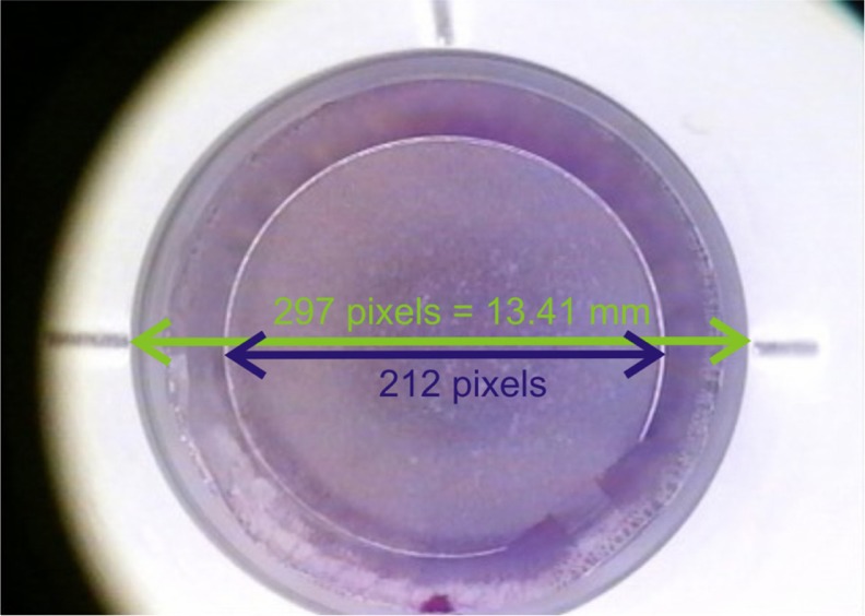
The pixel to mm conversion scale was established to be 0.0453 mm/pixel for the horizontal meridian, on the horizontal plane, along the nasal-temporal line (0–180 degrees, Figure 1). For the vertical meridian, on the coronal plane, along the superior–inferior line (90–270 degrees) the conversion scale was established to be 0.047 mm/pixel. This difference is attributed to a consistent compression ratio difference of the internal camera imaging optics. For the vertical meridian measurements, a virtual extension of the radial shape was assumed, ignoring deviation from the circular shape due to the canal.
Figure 1.
Image showing calibrated cone and flap.
Notes: Green arrow corresponds to applanation cone 13.41 mm across, as calculated previously. Blue arrow corresponds to flap diameter. Based on the scale established, the flap diameter was calculated to be 9.56 mm. This flap has no opaque bubble layer and no skip line.
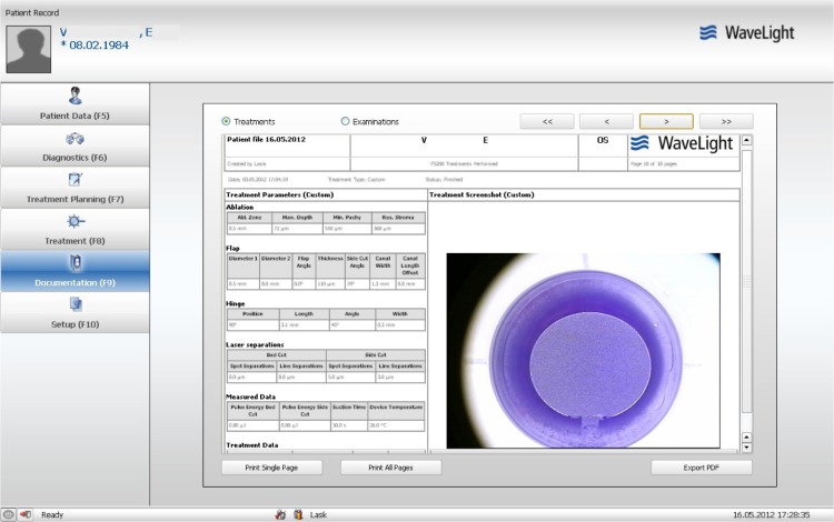
The designated flap parameters were imported from the patient’s image file, as shown in Figure 2. The images were uploaded in Adobe Photoshop CS5 version 12.04 (Adobe Systems Inc, San Jose, CA, USA). Pixel dimensions were determined using the “elliptical marquee tool” option set to “fixed size”. For example, a 296 × 285 elliptical marquee can be used to fit fully with the border of a 13.41 × 13.41 mm cone. Flap size was determined by selecting the elliptical marquee to match the size of the virtual circle that defines each slide, which is typically circular (see Figure 2, in which the flap was designed to be elliptical, ie, two different diameters, 8.50 mm and 8.00 mm). Conversely, using the established pixel to mm conversion scale, the pixel size of each flap dimension was converted to mm units. The pixel size for width was used to measure the horizontal dimension, and the pixel size for height was used to measure the vertical flap dimension (assuming an uninterrupted circular shape). Likewise, the “histogram tool” report was read to establish the flap area (assuming an uninterrupted circular shape) in pixels, which is subsequently converted to metric units (mm2).
Figure 2.
Patient documentation file showing a rare example of an elliptic flap intended for correction of astigmatic myopia.
Notes: There are two diameters, namely 8.5 mm horizontal meridian (0–180 degrees) and 8.00 mm for the vertical meridian (90–270 degrees). This flap has no opaque bubble layer or skip line, and in this respect represents the majority of cases in our study.
Determination of OBL dimensions and area
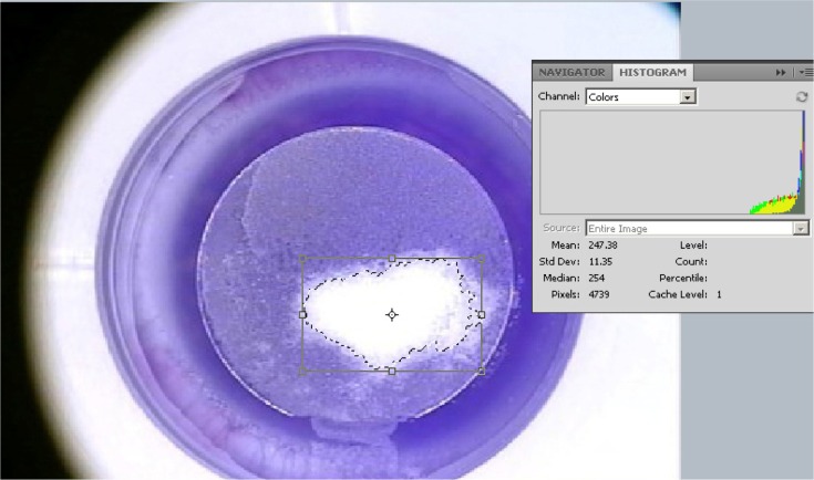
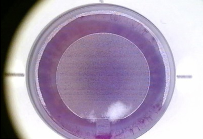
The OBL area was measured using the Magic Wand tool, whereby the area within the flap with “white” more than 50% was selected (Figure 3). Likewise, the pixel area was determined by the histogram tool, with conversion in mm2. The percentage of the OBL to total flap area, as determined in the previous step, was then computed.
Figure 3.
Methodology for measurement of opaque bubble layer area.
Notes: The area within the flap with white more than 50% is selected with the Magic Wand tool. The pixel area is determined by the histogram tool, and subsequently converted to metric units. This is the maximal opaque bubble layer encountered in our study in a minority of cases, not exceeding 20% of the flap surface.
Determination of skip line incidence
Determination of the presence of a skip line was made when at least five consecutive “comb” lines were determined to be present in the flap area.
Statistical analysis
Linear regression analysis was used to seek possible correlations between intended and achieved flap dimensions. Descriptive statistics (average, minimum, maximum, standard deviation, and range), comparative statistics, and linear regression were performed in Microsoft Excel 2010 (Microsoft Corporation, Redmond, WA, USA) and OriginLab version 8 (OriginLab Corp, Northampton, MA, USA). Analysis of variance between groups was performed using the Origin Lab statistics tool.
Results
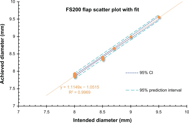
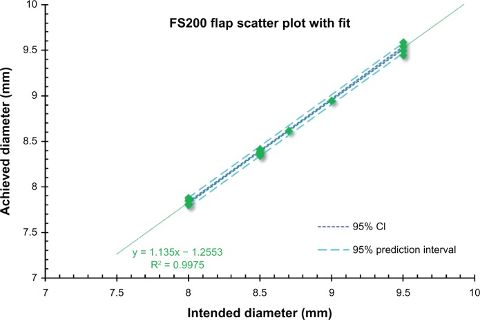
Of the 101 flaps examined, the majority (n = 63) were intended to 8.50 mm in diameter, one 8.70 mm, and one 9.00 mm (Table 1).The intended versus achieved flap dimensions according to intended size is summarized in Table 4. As stated earlier, separate measurements were undertaken for the horizontal meridian (0–180 degrees) and for the vertical meridian (90–270 degrees). The overall correlation between intended versus achieved horizontal size is shown in Figure 4 (P < 0.0001), while the correlation between the intended versus achieved vertical size is shown in Figure 5 (P < 0.0001).
Table 1.
Intended diameters of the flaps studied
| Flap intended diameter (mm) | n |
|---|---|
| 7.5 | 0 |
| 8.0 | 19 |
| 8.5 | 63 |
| 9.0 | 2 |
| 9.5 | 17 |
Table 4.
Intended versus achieved flap dimensions according to intended size
| Intended |
Achieved
|
|||||
|---|---|---|---|---|---|---|
|
Horizontal
|
Vertical
|
|||||
| All | OD | OS | All | OD | OS | |
| 8.00 | ||||||
| Mean | 7.85 | 7.86 | 7.85 | 7.83 | 7.83 | 7.83 |
| ±SD | 0.042 | 0.054 | 0.024 | 0.027 | 0.028 | 0.028 |
| Bias | −0.15 | −0.14 | −0.15 | −0.17 | −0.17 | −0.17 |
| 8.50 | ||||||
| Mean | 8.38 | 8.37 | 8.38 | 8.39 | 8.39 | 8.39 |
| ±SD | 0.03 | 0.03 | 0.02 | 0.02 | 0.02 | 0.02 |
| Bias | −0.12 | −0.13 | −0.12 | −0.11 | −0.12 | −0.11 |
| 8.70 | ||||||
| Bias | −0.04 | −0.09 | ||||
| 9.00 | ||||||
| Bias | −0.01 | −0.06 | ||||
| 9.5 | ||||||
| Mean | 9.56 | 9.56 | 9.56 | 9.53 | 9.52 | 9.54 |
| ±SD | 0.00 | 0.00 | 0.00 | 0.04 | 0.03 | 0.04 |
| Bias | 0.06 | 0.06 | 0.06 | 0.03 | 0.02 | 0.04 |
Abbreviation: SD, standard deviation.
Figure 4.
Overall correlation between intended versus achieved horizontal flap size.
Notes: The linear fit regression line and coefficient of linearity determination (R2) are shown. The 95% CI and 95% prediction interval lines are also plotted.
Abbreviation: CI, confidence interval.
Figure 5.
Overall correlation between vertical intended versus achieved flap size.
Notes: The linear fit regression line and the coefficient of linearity determination (R2) are shown. The 95% CI and 95% prediction interval lines are also plotted.
Abbreviation: CI, confidence interval.
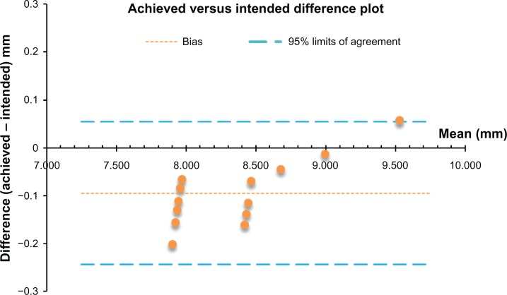
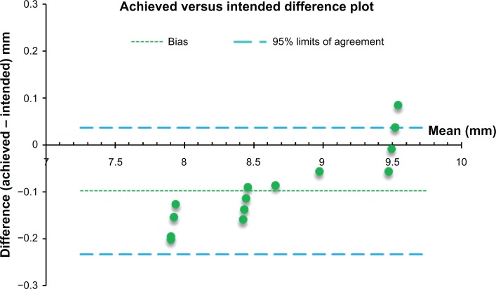
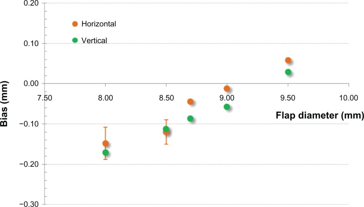
Because of the nature of the measurements involved, ie, a grouped set of data, difference plots were drawn to demonstrate specific bias between the intended versus achieved size. A Bland-Altman plot for the intended versus achieved horizontal size is shown in Figure 6, and the intended versus achieved vertical size is shown in Figure 7. A study of measured bias (difference of achieved vs intended diameter) is presented in Figure 8.
Figure 6.
Bland-Altman plot of horizontal flap diameter measurements with bias and 95% limits of agreement.
Figure 7.
Bland-Altman plot of horizontal flap diameter measurements with bias and 95% limits of agreement.
Figure 8.
Bias, defined as difference of achieved vs intended flap diameter, measured in mm. Horizontal refers to the horizontal plane, along the nasal-temporal line, and vertical refers to the coronal plane, along the superior–inferior line.
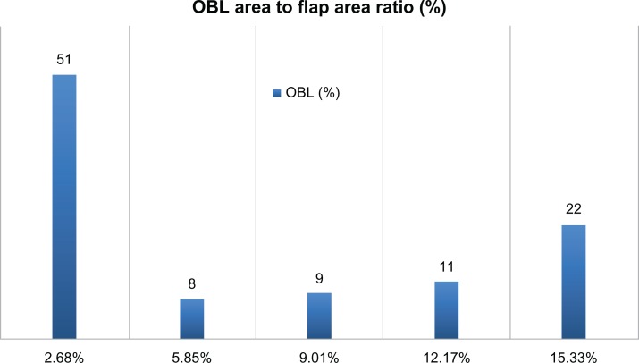
The incidence of OBL (Table 2), was measured to have a mean area of 5.8% (minimum 0%, maximum 20.3%). No significant variation was found between OD and OS eyes (Table 3). Of the 101 flaps examined, 31 showed no OBL. A histogram for incidence of OBL is shown in Figure 9. Of the 101 flaps examined, nine (8.91%) showed a noticeable skip line.
Table 2.
Incidence of opaque bubble layer
| Area covered (%) | Incidence (n) | Total flaps (n) | |
|---|---|---|---|
| Opaque bubble layer | |||
| 0.00–2.68 | Mean −1 × SD | 51 | 50.50 |
| 2.67–5.85 | Mean −0.5 × SD | 8 | 7.92 |
| 5.86–9.01 | Mean +0.5 × SD | 9 | 8.91 |
| 9.02–12.17 | Mean +1 × SD | 11 | 10.89 |
| 12.18–15.33 | Mean +1.5 × SD | 22 | 21.78 |
Note: Area increments are determined by mean coverage (5.8%) and SD.
Abbreviation: SD, standard deviation.
Table 3.
Opaque bubble layer in all eyes, and in OD and OS eyes
|
OBL incidence (coverage)
|
|||
|---|---|---|---|
| All eyes | OD | OS | |
| Mean | 6% | 6% | 7% |
| Maximum | 20% | 18% | 20% |
| Minimum | 0% | 0% | 0% |
| SD | 6% | 6% | 7% |
Abbreviation: SD, standard deviation.
Figure 9.
Histogram of incidence of OBL.
Note: Mean OBL area to flap area ratio (in %) was 5.85.
Abbreviation: OBL, opaque bubble layer.
Discussion
Accuracy and precision of flap size
Despite an excellent overall correlation between intended and achieved flap size (Pearson’s r2 = 0.96; P < 0.001 for the horizontal and r2 = 0.997; P < 0.001 for the vertical meridian), there was a very small bias between intended and achieved flap size, independent of the meridian (vertical or horizontal) but related to the indented flap diameter. Specifically, for the small flap size (diameter 8.00 mm), the mean achieved flap diameter was minimally smaller, ie, for the horizontal diameter 7.85 ± 0.04 (range 7.93 max–7.80 min) mm and for the vertical diameter 7.83 ± 0.03 (range 7.87 max–7.80 min) mm. Therefore, precision as indicated by the standard deviation was found to be between ±0.04 and ±0.03 mm. Accuracy, as determined by the bias related to the intended flap size was also impressive at −0.15 and −0.17 mm, respectively, for the horizontal and vertical diameters. No variation was noted between OD and OS eyes, which further confirms the accuracy of these findings (Table 3). As shown in Figure 8, accuracy and precision was similar for the 8.50 mm flap diameter. Specifically, the bias was −0.12 mm (mean 8.38 ± 0.03 [range 8.43 max–8.34 min] mm for the horizontal diameter and 8.39 ± 0.02 [range 8.41 max–8.34 min] mm for the vertical diameter), and was also insignificant for the 8.70 mm and 9.00 mm flaps, although there were just two cases with these intended numbers. In regard to the largest flap size (9.50 mm), this small bias became positive. Specifically, the average achieved diameter was 9.56 ± 0.00 mm for the horizontal diameter and 9.53 ± 0.03 mm for the vertical diameter.
However, it is noted that in a similar study12 involving porcine cadaver eyes and the prototype 200 kHz femtosecond laser UltraFlap (WaveLight GmbH, Erlangen, Germany), the successor of which is the FS200 femtosecond laser (Alcon, Fort Worth, Texas), a positive bias of approximately +0.03 to +0.06 mm was found for all flap diameters, and the flap diameter precision was found to correspond to a larger standard deviation (±0.10 to ±0.15 mm). This wider uncertainty may be attributed to the fact that the study was conducted using mechanical measurements (sliding caliper). Thus, we introduce this novel technique as a new benchmark for evaluating flap dimensions in LASIK. In another recently published study that examined the predictability of dimensions for flaps created using a pendular microkeratome,13 it was found that the microkeratome achieved a mean flap diameter of 9.2 mm using the 9.0 mm ring and 9.8 mm using the 10.0 mm ring, indicating a precision in the order of 0.2 mm.
A similar result was reported in another study,14 in which the corneal flap was assessed manually by the surgeon during the procedure, with flaps created using a “planar” bladed keratome. In that study, it was found that the microkeratome achieved a mean flap diameter of 9.2 ± 0.2 mm using the 9.0 ring. We have encountered a similar challenge with the manual flap dimension measurement by the surgeon.15–17
In both studies,13,14 the precision was found to be at least 0.15 mm, which is a very large standard deviation and more uncertain than the corresponding FS200-created flaps, as measured by our digital technique.
Incidence of OBL
Our study showed a small incidence of OBL because of the continuous improvement in “channeling” of gas buildup outside the cornea at the limbus during lamellar dissection of the cornea. This is also always on the hinge side of the flap. The reason why the OBL appeared always at the hinge side of the flap is that the OBL is caused by a buildup of trapped gas. As lamellar dissection by the laser progresses, the lamellar pocket space created is larger, thereby reducing this phenomenon. The type of OBL observed in our study is the so-called “delayed” or “soft” as opposed to “hard” or “advancing” OBL ahead of the laser breakdown raster line. Thus, appearance of a delayed OBL does not interfere with focusing of the laser during creation of the flap.
We speculate that the reason why the incidence of OBL was so small is related to the innovative way in which the FS200 laser tackles this problem, ie, creation of the flap starts with a venting dissection corridor fashioned by the surgeon within the hinge of the flap, which acts as a venting “chimney” for the lamellar dissection part of the flap creation procedure. Other lasers, such as the IntraLase™ (Abbott Medical Optics Inc, Santa Ana, CA, USA), create a vertical gas pocket near the hinge, acting as an escape route for gas which has built up within the cornea. Our findings indicate that half of the flaps created had <2.7% of OBL in the total flap area (with 30% having no OBL). The mean OBL area was 4.1 mm2, corresponding to just 6% of the flap area (Figure 9). The single largest OBL incidence had an area of 14.34 mm2, representing 20.34% of the total 70.52 mm2 flap area (8.5 mm diameter, Figure 10). In all instances of OBL, the nebulation appeared on the hinge side of the flap, ie, the lower part as seen from the operator’s side.
Figure 10.
Image of a flap demonstrating skip lines.
Incidence of skip lines
There were nine cases of skip lines in the 101 flaps examined. In most cases, there was no or very little simultaneous appearance with OBL. Specifically, the percentage area of OBL on the flaps that demonstrated skip lines was just 1%, and most appeared on flaps with zero OBL.
It has been theorized that skip lines may be a result of increased heart rate pulsation that translates into a vibrating cornea during creation of the flap or an effect of accumulating gas within the lamellar femtosecond laser-created separation that causes slight jumps in the separation sequence. However, the sequence of the skip lines in a lamellar cut that takes 5 seconds would indicate a heart rate of over 150 beats per minute, which is clearly not the case clinically.
Our alternative explanation is that skip lines are caused by gas vented through the channel into the conjunctival area beyond the limbus (depending on channel offset and applanation). Release of this pressure might cause this optical finding, but it is not clinically significant. At any rate, the appearance of skip lines does not seem to have any clinical significance in the progression or outcome of LASIK procedures.
Conclusion
Our study indicated acceptable accuracy (less than −0.12 mm, up to +0.06 mm) for flap creation using the FS200 femtosecond laser. Flap precision was good in all planned groups, with the most precise flaps being those for an intended flap diameter of 9.5 mm (±0.00 mm to ±0.04 mm for the horizontal and vertical meridians, respectively). OBL was clinically nonexistent, with only a trace presence in some flaps. Specifically, 50% of the flaps showed <2.7% of OBL in the total flap area, and only one of five flaps could be characterized as having actual OBL (which is still minimal) and ranging up to approximately 16% of the flap area. Likewise, only nine (9%) of the 101 flaps examined were identified to have skip lines.
Footnotes
Disclosure
AJK is a consultant to Alcon. GA has no conflicts of interest to declare for this work.
References
- 1.Sugar A. Ultrafast (femtosecond) laser refractive surgery. Curr Opin Ophthalmol. 2002;13(4):246–249. doi: 10.1097/00055735-200208000-00011. [DOI] [PubMed] [Google Scholar]
- 2.Vogel A, Günther T, Asiyo-Vogel M, Birngruber R. Factors determining the refractive effects of intrastromal photorefractive keratectomy with the picosecond laser. J Cataract Refract Surg. 1997;23(9):1301–1310. doi: 10.1016/s0886-3350(97)80107-1. [DOI] [PubMed] [Google Scholar]
- 3.Ratkay-Traub I, Ferincz IE, Juhasz T, Kurtz RM, Krueger RR. First clinical results with the femtosecond neodynium-glass laser in refractive surgery. J Refract Surg. 2003;19(2):94–103. doi: 10.3928/1081-597X-20030301-03. [DOI] [PubMed] [Google Scholar]
- 4.Nordan LT, Slade SG, Baker RN, Suarez C, Juhasz T, Kurtz R. Femtosecond laser flap creation for laser in situ keratomileusis: six-month follow-up of initial US clinical series. J Refract Surg. 2003;19(1):8–14. doi: 10.3928/1081-597X-20030101-03. [DOI] [PubMed] [Google Scholar]
- 5.Chen S, Feng Y, Stojanovic A, Jankov MR, Wang Q. IntraLase femtosecond laser vs mechanical microkeratomes in LASIK for myopia: a systematic review and meta-analysis. J Refract Surg. 2012;28(1):15–28. doi: 10.3928/1081597X-20111228-02. [DOI] [PubMed] [Google Scholar]
- 6.Holzer MP, Rabsilber TM, Auffarth GU. Femtosecond laser-assisted corneal flap cuts: morphology, accuracy, and histopathology. Invest Ophthalmol Vis Sci. 2006;47(7):2828–2831. doi: 10.1167/iovs.05-1123. [DOI] [PubMed] [Google Scholar]
- 7.Mai ZB, Liu SB, Nie XL, Sun HX, Xin BL, Tang XX. Predictability of the corneal flap creation with the femtosecond laser in LASIK. Zhonghua Yan Ke Za Zhi. 2012;48(5):390–393. Chinese. [PubMed] [Google Scholar]
- 8.Pietilä J, Huhtala A, Mäkinen P, Uusitalo H. Laser in situ keratomileusis enhancements with the Ziemer FEMTO LDV femtosecond laser following previous LASIK treatments. Graefes Arch Clin Exp Ophthalmol. 2012 Jul 20; doi: 10.1007/s00417-012-2110-9. [Epub ahead of print.] [DOI] [PubMed] [Google Scholar]
- 9.Kanellopoulos AJ, Pe LH, Perry HD, Donnenfeld ED. Modified intra-corneal ring segment implantations (INTACS) for the management of moderate to advanced keratoconus: efficacy and complications. Cornea. 2006;25(1):29–33. doi: 10.1097/01.ico.0000167883.63266.60. [DOI] [PubMed] [Google Scholar]
- 10.Kaiserman I, Maresky HS, Bahar I, Rootman DS. Incidence, possible risk factors, and potential effects of an opaque bubble layer created by a femtosecond laser. J Cataract Refract Surg. 2008;34(3):417–423. doi: 10.1016/j.jcrs.2007.10.026. [DOI] [PubMed] [Google Scholar]
- 11.Hurmeric V, Yoo SH, Fishler J, Chang VS, Wang J, Culbertson WW. In vivo structural characteristics of the femtosecond LASIK-induced opaque bubble layers with ultrahigh-resolution SD-OCT. Ophthalmic Surg Lasers Imaging. 2010;41(Suppl):S109–S113. doi: 10.3928/15428877-20101031-08. [DOI] [PubMed] [Google Scholar]
- 12.Khoramnia R, Salgado JP, Lohmann CP, Kobuch KA, Winkler von Mohrenfels C. Precision, morphology, and histology of corneal flap cuts using a 200-kHz femtosecond laser. Eur J Ophthalmol. 2011;22(2):161–167. doi: 10.5301/EJO.2011.8376. [DOI] [PubMed] [Google Scholar]
- 13.Paschalis EI, Labiris G, Aristeidou AP, Foudoulakis NC, Koukoula SC, Kozobolis VP. Laser in situ keratomileusis flap-thickness predictability with a pendular microkeratome. J Cataract Refract Surg. 2011;37(12):2160–2166. doi: 10.1016/j.jcrs.2011.05.044. [DOI] [PubMed] [Google Scholar]
- 14.Paschalis EI, Aristeidou AP, Foudoulakis NC, Razis LA. Corneal flap assessment with Rondo microkeratome in laser in situ keratomileusis. Graefes Arch Clin Exp Ophthalmol. 2011;249(2):289–295. doi: 10.1007/s00417-010-1433-7. [DOI] [PubMed] [Google Scholar]
- 15.Kanellopoulos AJ. Topography-guided hyperopic and hyperopic astigmatism femtosecond laser-assisted LASIK: long-term experience with the 400 Hz eye-Q excimer platform. Clin Ophthalmol. 2012;6:895–901. doi: 10.2147/OPTH.S23573. [DOI] [PMC free article] [PubMed] [Google Scholar]
- 16.Kanellopoulos AJ, Conway J, Pe LH. LASIK for hyperopia with the WaveLight excimer laser. J Refract Surg. 2006;22(1):43–47. doi: 10.3928/1081-597X-20060101-10. [DOI] [PubMed] [Google Scholar]
- 17.Kanellopoulos AJ, Pe LH, Kleiman L. Moria M2 single use microkeratome head in 100 consecutive LASIK procedures. J Refract Surg. 2005;21(5):476–479. doi: 10.3928/1081-597X-20050901-09. [DOI] [PubMed] [Google Scholar]


