Abstract
T2* weighted fMRI at high and ultra high field (UHF) is often hampered by susceptibility-induced, through-plane, signal loss. Three-dimensional tailored RF (3DTRF) pulses have been shown to be an effective approach for mitigating through-plane signal loss at UHF. However, the required RF pulse lengths are too long for practical applications. Recently, parallel transmission (PTX) has emerged as a very effective means for shortening the RF pulse duration for 3DTRF without sacrificing the excitation performance. In this article, we demonstrate a RF pulse design strategy for 3DTRF based on the use of multi-slice PTX 3DTRF to simultaneously and precisely recover signal with whole-brain coverage. Phantom and human experiments are used to demonstrate the effectiveness and robustness of the proposed method on three subjects using an eight-channel whole body parallel transmission system.
Keywords: RF pulse design, parallel transmission, susceptibility artifacts, functional MRI, ultra high field
INTRODUCTION
Ultra high magnetic field (UHF) MRI has gained considerable interest in recent years due to its improved signal-to-noise ratio (SNR) capabilities and the enhanced contrast mechanisms that it provides (1). Unfortunately, the same mechanisms that lead to enhanced contrast sometimes lead to increased susceptibility artifacts for long-established MRI applications. Functional MRI (fMRI), in particular, is severely affected by both increased physiological noise and susceptibility-induced signal loss at UHF. Susceptibility-induced artifacts usually appear as geometric distortions and/or signal loss at some important functional areas of the brain, such as the orbital frontal and inferior temporal cortices (2), and limit the effectiveness of blood oxygen level-dependent (BOLD) fMRI studies of mood and related disorders at fields higher than 3 Tesla (3,4).
A number of approaches have been proposed to mitigate the susceptibility-induced signal loss. One common method employs optimization of the slice and imaging parameters. Typically, signal loss can be mitigated by the reduction of the size of image voxels (5,6). Likewise, through-plane phase cancellation of spin signals can be alleviated via the reduction of the slice thickness, albeit at the expense of a reduction in brain coverage per repetition time. Refs. (7,8) propose the use of an external coil for localized shimming to recover signal loss, which is effective to a limited extent in improving field homogeneity. Nevertheless, for long fMRI sessions, placement of shimming hardware on the subject leads to significant discomfort and might not be useful for refocusing the magnetization in deeper brain structures where the local shim coil profile will be weaker.
Another class of signal recovery methods, dubbed z-shim, use z-gradient lobes to compensate for through-plane dephasing (9-12). A z-gradient lobe, applied after slice excitation, can create a linear phase along the z dimension that could cancel out the dephasing due to localized field inhomogeneities. Since gradient lobes are non-selective and the extent of dephasing varies as a function of voxel location, one needs to acquire multiple sub-images, using different gradient areas, to refocus different spatial locations within the image. These sub-images can then be combined to form a final image free of signal loss. Because of the need to acquire several sub-images per spatial location, z-shim methods necessarily lead to a reduction in the temporal resolution of the fMRI scans.
To circumvent the limitations of the approaches described above, Stenger et al (13) introduced the three-dimensional tailored RF (3DTRF) method to reduce susceptibility artifacts in T2* weighted fMRI studies. This approach has some important conceptual advantages. First, it imposes few constraints on the imaging parameters, for example, thin slices are not conceptually required. Second, it does not require multiple sub-image acquisitions for a single slice, and, therefore, it does not sacrifice temporal resolution. Third, it does not require additional placement of external hardware on the subject’s head. Finally, this method can be applied in conjunction with many other existing methods, such as thin slice, localized shimming and z-shim for maximal signal recovery. Using the original formulation of 3DTRF, Yip et al (14) proposed an advanced version of the 3DTRF method to effectively improve slice selection fidelity and shorten RF pulse duration. This approach, while conceptually powerful, was somewhat limited by the long duration (~15ms) of the resulting RF pulses. Spectral-spatial RF pulse design (15, 16) has been also explored for reducing susceptibility-induced signal loss. This method relies on the assumption that a priori estimates of resonance frequency offset accurately predicts through-plane dephasing. As this assumption may not be valid at multiple slice locations and different human subjects, the effectiveness of the approach is necessarily limited.
The long pulse durations in the 3DTRF method could be addressed through the use of parallel transmission technology (17-19) in which RF pulse durations can be dramatically reduced by undersampling the k-space trajectory. Generalization of the 3DTRF method for parallel transmission is a nontrivial problem due to the complexity of the parallel transmission RF pulse design, which could be broadly grouped into small-tip-angle (19) and large-tip-angle (20, 21) techniques. In this work, we propose a multi-slice, 3DTRF approach based on a small-tip-angle pulse design for the recovery of susceptibility-induced signal loss in ultra high field fMRI.
This article first introduces the basic principles of 3DTRF (14) and small-tip-angle (19) parallel transmission RF pulse design. Afterwards, we evaluate the proposed method in a homogeneous cylinder water phantom and demonstrate the recovery of signal loss across multiple slices. Finally, we apply the proposed methodology in vivo using multi-slice Gradient Echo (GRE) and two-dimensional echo planar (EP) BOLD sequences in multiple subjects. Our results show that the proposed RF pulse design method is successful at signal loss recovery across different brain regions over the volume of the whole brain.
THEORY
Principle of the 3DTRF method
In multi-dimensional excitation, the pixel size in the through plane direction is often larger than its in plane counterpart. Consequently, through-plane signal loss artifacts are of larger magnitude relative to in-plane signal loss. The goal of the 3DTRF pulse design method is to recover the signal loss via pre-compensation of the through-plane phase variation during the RF pulses excitation. We use the derivations in Ref. 14 to calculate the required pre-compensation phase, which is the negative of the phase variation in the presence of an inhomogeneous main field with frequency offset Δf (x, y,z). Assuming the slice location z0 is excited with echo time of TE, the duration between the flip down of magnetization and the acquisition of the center of the k-space, the through-plane phase variation that dominates the signal loss at in-plane location (x,y) can be modeled with the following first order linear relationship,
| [1] |
where (x,y;z0) denotes the mean frequency offset around z0 along the axial direction and can be defined by,
| [2] |
where p(z − z0) is the excited slice profile at the center of slice location z0 . The aim of the aforementioned normalization is to exclude the contribution of the in-phase evolution of the magnetization in the through-plane phase variation. For T2* weighted contrast in ultra high field fMRI, the phase variation is very rapid due to severe main field inhomogeneities. Thus, phase cancellation during the readout leads to MR signal loss because the voxel intensities are generated from the integration of the magnetization in those regions. Therefore, one way to recover the signal loss is to pre-compensate the through-plane phase variation in Eq. [1] within the excitation profile. We denote Dorig(r,z0) as the original slice-selective excitation patterns at multiple slices. Slice selection profile along the through-plane direction is denoted by p(z − z0) with the peak at z0. By negating the through-plane phase variation, the precompensated excitation pattern can be formulated as,
| [3] |
Then the precompensated excitation pattern Dprecom(r,z0) will be the new desired excitation pattern. Ideally, the phase pattern of Dprecom(r,z0) would cancel out the through-plane dephasing during TE , and spins would be aligned in phase when the center of k-space acquired at TE. This advanced 3DTRF method (14) has been investigated and successfully demonstrated to mitigate signal loss at 3T. However, as aforementioned earlier, the exceedingly long pulse duration significantly hinders its performance in ultra high field (i.e., 7T).
Parallel Transmission RF Pulse Design
The most widely used small-tip-angle parallel transmission (PTX) RF pulse design is the spatial domain method proposed by Grissom et al (19). In the regime of small-tip-angle excitation (22), the excitation pattern produced by multiple coils (1,…, L) can be approximated by the integration of Fourier kernel with an excitation k-space trajectory defined as , weighted by RF pulses B1{b1(t),…,bL(t)} and spatially dependent transmit sensitivity map (B1+ map) S{S1(r),…,SL(r)},
| [4] |
where γ is the gyromagnetic ratio, the equilibrium magnetization is given by M0 , T is the duration of gradient G and Δf denotes the main field frequency offset. After discretization in space and time dimensions, Eq. [4] can be written as a matrix form, where the encoding matrix A incorporates the Fourier kernel and frequency offset. With this formulation, RF pulses can be designed by solving the following least-square minimization problem,
| [5] |
Here, D is the desired excitation pattern, the optimization is performed over the region of interest (ROI) weighted by the spatial error weighting mask W , and the deposited RF power is controlled by the Tikhonov regularization term . Finally, RF pulses can be efficiently solved through Conjugate Gradient (CG) method (19) minimization.
Multi-slice RF Pulse Design of PTX 3DTRF
The Multi-slice RF pulse design for signal recovery is an extension of the previously derived formulation where we combine the 3DTRF method with parallel transmission techniques. To control the excitation at a set of N different slices, we extend the set of equations as Eq. [4] to different slices and concatenate the precompensated desired patterns Dprecom(r,zn) = {Dslice1,…, DsliceN} in Eq. [3] where the slice-selective peak is at the slice location of zn (n=1,...,N), the spatial sensitivity (B1+) maps of total slices Stotal = {Sslice1,…,SsliceN} and the aforementioned encoding matrix of total slices Atotal = {Aslice1,…, AsliceN} where frequency offset maps ( Δf ) are encoded. Finally, we can formulate the following concatenated equation for multi-slice signal recovery,
| [6] |
The RF pulses for the signal recovery at the slice location of zn can be efficiently solved via Conjugate Gradient optimization. Then, the RF pulses of signal recovery for other slices can be obtained through the same procedure after shifting the location of excited peak (zn) from slice 1 to slice N. In other words, the slice selection profile p(z − zn) is modified according to the location of the excited peak. Because the concatenated matrix of right side of Eq. [6] does not change with the excitation profile, fast parallel computation can be implemented via the use of multiple CPUs.
METHODS
Hardware
All experiments were performed on a Siemens 7T whole-body Magnetom scanner (Siemens Healthcare Erlangen, Germany) equipped with an 8-channel parallel transmission (PTX) RF system and a gradient set with maximum amplitude of 40mT/m and maximum slew rate of 170 mT/m/ms. An 8-channel transmit/receive volume birdcage head coil was used for all experiments. Phantom experiments were performed on a cylindrical homogeneous water phantom filled with 1.25 g/liter of nickel sulfate and 5 g/liter of sodium chloride. To mimic the human structure near the tissue and air cavities, we attached a round bottom flask filled with air to the inner top of the water phantom to induce an inhomogeneous field.
B1+ and Main Field Frequency Mapping
One of the most important ingredients for effective parallel transmission pulses design is the rapid and accurate mapping of the B1+ maps of the transmit coil array in both experimental phantoms and humans. Multi-slice B1+ maps were acquired with a novel fast B1+ mapping method first introduced by Zhao et al (23). This method can efficiently estimate relative B1+ maps from one small-tip-angle excitation since absolute B1+ maps are not required for parallel transmission RF pulse design. Therefore, the total acquisition time required for the B1+ maps from 21 slices was only 1min and 40 sec. The magnitude and phase of the B1+ maps of the central slice for one representative subject are shown in Fig. 1. A FLASH sequence with TE1=3.7 ms and TE2=4.7 ms, respectively, was used to estimate the frequency offset map in Hertz.
FIG. 1.
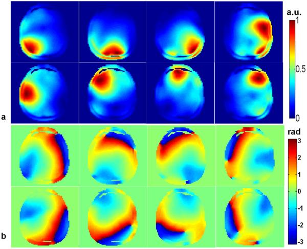
Magnitude (a) and phase (b) of B1+ map measured at the central slice of one subject with the eight-channel parallel transmission coil.
Pulse Design
For multi-slice signal recovery, we applied the desired phase pattern to an otherwise homogeneous excitation pattern. We employed a flyback five-rung fast-kz trajectory (24) centered at the k-space center to obtain parallel transmission RF pulses that uniformly excite a Gaussian-shaped slice profile with full-width half maximum (FWHM) of 5mm and flip angle=15°, TE=16ms. Tikhonov regularization parameter of 10 and 50 iterations are used during the conjugate gradient optimization.
In our PTX 3DTRF pulse design, we have two options for the gradient dwell time: namely, a “standard” method with a gradient dwell time of 10us and time-interpolation method with a gradient dwell time of 5us. The default gradient dwell time in Siemens 7T system is 10us. However, we can reduce it at the design stage but the minimal gradient dwell time is still 10us at the imaging stage. We can reduce the dwell time at the design stage in order to achieve higher gradient and slew rate without adding the ghost artifacts. This is the rationale that two approaches of PTX 3DTRF pulse design are proposed. The trajectory of the standard method was designed with a maximum gradient of 18mT/m and a maximum slew rate of 150mT/m/ms. The resulting pulse duration was approximately 8.5ms. For the interpolation method, the maximum gradient and slew rate were constrained to 36mT/m and 150mT/m/ms, respectively. The corresponding pulse length was about 6ms, which is much shorter than that obtained with the standard method. Therefore the time-interpolation method is expected to be more robust to the effects of main field inhomogeneity because of its short pulse duration. Further reduction in pulse duration (~4ms) can be obtained with the use of non-flyback fast kz trajectory, but careful calibration must be performed. However, it is still quite difficult to completely eliminate the effect of mis-calibration and then leads to ghost artifacts along the through-plane direction (27).
After determining the required B1+ maps, field maps, target pattern and trajectory, we designed the parallel transmission, multi-slice signal recovery 3DTRF pulses using the Conjugate Gradient method implemented with Matlab R2011a (MathWorks, In., Natick, MA, USA) on a Linux PC computing platform with two 2.33GHz quad-core Intel Xeon processors. For the standard method, 5min of computation time were needed in order to calculate the RF pulses of 7 slices. The computational time of the corresponding time-interpolation method was 7min (due to higher sampling rate).
Phantom Experiments
To induce an inhomogeneous field in water phantom, we attached a round bottom flask to mimic the susceptibility-induced artifact in humans. The created inhomogeneous field led to signal loss in GRE images, acquired using SINC pulse under the circular polarization (CP) mode of the RF coil. We subsequently attempted to simultaneously recover the signal loss at different slice locations with the proposed method as per the methodology described above. The SINC pulses in the GRE sequence were then replaced with the pulses designed by the proposed method while keeping other imaging parameters the same. We compared the GRE images acquired with SINC pulses and PTX 3DTRF pulses. Three-dimensional slice-selective excitation was performed in order to confirm the fidelity of the excited slice volume. The imaging parameters of GRE sequence are as follows, TE/TR=16/500ms, FOV=220mm, flip angle=15, Resolution=256 × 256.
In-vivo Experiments
To illustrate the benefit of the proposed methods, the same protocol as described in the phantom experiments was used for the in-vivo experiment. Two sets of GRE images acquired from three healthy volunteers were compared to demonstrate the efficiency of the proposed methods. In addition to GRE images acquired with the SINC and PTX 3DTRF pulses, we also acquired EPI images for the same slice locations. The imaging parameters of EPI sequence are as follows, TE/TR=16/500ms, FOV=220mm, flip angle=15, Resolution=256 × 256, GRAPPA=2. Note that for both GRE and EPI sequences, multi-slice RF pulses are deployed in one single scan to simultaneously recover multi-slice signal loss at different slice locations. Moreover, to prove the robustness of the time-interpolation method in the presence of field inhomogeneities, we compared the images acquired with both dwell time methods for severe and mild main field inhomogeneities. Three healthy volunteers were scanned after providing informed consent a protocol approved by the Institutional Review Board (IRB) of the University of Pittsburgh. For both phantom and human experiments, standard linear shimming was performed before RF pulse design.
RESULTS
Phantom Experiments
Figure 2 presents a comparison of GRE images of the custom-made water phantom experiments excited by the (a) SINC and (b) PTX 3DTRF pulses. As can be seen, the susceptibility differences induced severe signal loss when the routine SINC pulse is employed. By contrast, with the use of PTX 3DTRF pulses with a precompensated phase pattern, signal recovery can be obtained at multiple slice locations while excitation at the other remaining regions remains unaltered.
FIG. 2.

Comparison of the performance between the SINC and PTX 3DTRF pulses. a: (Top row) excitation patterns obtained with the SINC pulses. b: (Bottom row) excitation patterns obtained with PTX 3DTRF pulses. Significant signal recovery at multiple slices is observed when the PTX 3DTRF pulses are used.
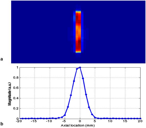
To evaluate the fidelity of excitation profile, we image the slice volume excited by the PTX 3DTRF using 3D imaging sequence. Note that the desired patterns are the multiple slices of homogeneous excitation windowed by the Gaussian profile with a FWHM of 5mm. Figure 3 shows the excitation magnitude profile at multiple slice locations. The same axial location in x-axis is used in Figure 3(a) and (b), which shows the slice location along the through-plane direction. The y-axis in Figure 3(a) is defined as the projection of in-plane FOV with resolution of 256. One can observe, from the (a) 2D and (b) 1D profiles, excellent slice-selective excitation is illustrated.
FIG. 3.
The 2D (a) and 1D (b) through-plane profiles obtained from the excitation patterns using the PTX 3DTRF pulses in Fig. 2b.
In vivo Experiments
Figure 4 shows multi-slice field maps acquired from three subjects. The images demonstrate that frequency offsets are very large at ultra high field. From the results on Fig. 4, subject A exhibits the worst main field inhomogeneity and concomitant signal loss in the neighborhood of the orbital frontal cortex. By comparison, the frequency offsets of subject C are relatively small and subsequently leads to more successful recovery of signal loss.
FIG. 4.
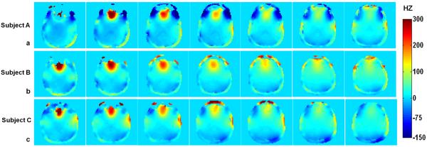
Field maps acquired at different slice locations for three different subjects. Note that the field maps are highly inhomogeneous and frequency offsets are very large. In addition, subject A shows more severe inhomogeneity than the other two, which leads to a more limited amount of signal recovery.
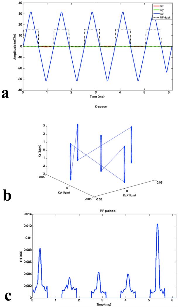
A more in-depth depiction of the distributions of frequency offsets is presented in Fig. 5. The mean frequency offsets of subject A (Fig. 5a), subject B (Fig. 5b) and subject C (Fig. 5c) are −19.9 Hz, 16.9 Hz and 13.5 Hz, respectively. And the corresponding standard deviations are 68.7, 46.5 and 42.8, respectively. As shown in Fig 5a, an additional distribution of off-resonance close to the zero frequency offset leads to the larger frequency offsets than those of subject C. Figure 6 shows the gradient waveforms, k-space trajectory and resulting sum of RF pulses for the case of subject A. RF pulse was designed with a maximum gradient of 36mT/m and a maximum slew rate of 150mT/m/ms. Pulse duration is 6.15ms.
FIG. 5.
Distribution of frequency offsets for the three different subjects. The mean and standard deviation of subject A (a) is −19.9 Hz (SD= 68.7), subject B (b) is 16. 9 Hz (SD= 46.5), and subject C (c) is 13.5 Hz (SD= 42.8), respectively. Note that another peak besides the main peak in Fig. 5a, results in the large frequency offset in subject A.
FIG. 6.
(a) Gradient waveforms, (b) k-space trajectory and (c) resulting sum of RF pulses for the case of subject A. Note that pulse duration is 6.15ms.
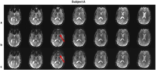
Figure 7 shows the multi-slice excitation for the GRE sequence on subject A using (a) SINC pulses, (b) standard PTX 3DTRF method and (c) time-interpolation PTX 3DTRF method, respectively. For the excitation using SINC pulses (Fig. 7a), significant signal loss can be observed at multiple slice locations. With the use of PTX 3DTRF (Figs. 7b and 7c), signal loss is simultaneously and precisely recovered at different regions over multiple slice locations. Additionally, the improvement in signal recovery is more evident with the use of time-interpolation method, as indicated by the solid arrows in Figs. 7b and c.
FIG. 7.
Gradient echo (GRE) images acquired in the brain of subject A, using (a) SINC pulses, (b) standard PTX 3DTRF method and (c) time-interpolation PTX 3DTRF method, respectively. Note that the recovery of signal loss can be observed at most of the slice locations. The signal recovery can be further improved using time-interpolation PTX 3DTRF method, as indicated by solid arrows.
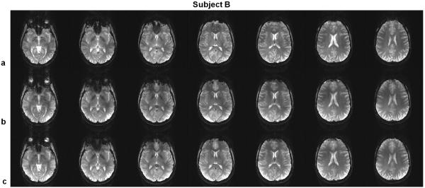
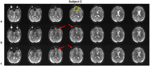
The recovery of signal loss can also be noticeably observed on subject B (Fig. 8), where the frequency offsets from the field maps are smaller than those of subject A. It is clear that the SINC-pulse-excited GRE images suffered extensive signal loss at different regions. Remarkably, the use of PTX 3DTRF pulses can be effective in recovering signal at regions other than the orbital-frontal lobe cortex. A more obvious comparison is presented in Fig. 9 where the improved regions are indicated by the arrows. Furthermore, even though the frequency offsets are small on subject C, the improvement of the time-interpolation method is still noticeable. At the same time, regions that were originally not plagued by the signal loss remained unaffected by the PTX 3DTRF pulses.
FIG. 8.
Gradient echo (GRE) images acquired in the brain of subject B, using (a) SINC pulses, (b) standard PTX 3DTRF method and (c) time-interpolation PTX 3DTRF method, respectively.
FIG. 9.
Gradient echo (GRE) images acquired on Subject C using (a) SINC pulses, (b) standard PTX 3DTRF method and (c) time-interpolation PTX 3DTRF method, respectively. The result documents the same findings as in Figs. 7 and 8. Noticeably, not only the orbital-frontal lobe regions but also other regions are beneficial for the use of the PTX 3DTRF pulses. In addition, the improvement of time-interpolation method of PTX 3DTRF is significant as indicated by solid arrows.
Table 1 summarizes the effectiveness of the proposed methods by comparing the mean signal intensity within a region-of-interest (ROI) (which is labeled with the yellow squares in Fig. 9a) at the central slice in Figs. 7, 8 and 9 between SINC pulses and standard and time-interpolation PTX 3DTRF methods for all subjects. Note that the mean signal intensity in the case of SINC pulses was normalized to 1. Significant improvement (> 20%) can be obtained by both PTX methods even at the worst case (Subject A).
Table. 1.
Compare the mean signal intensity within ROI (which is labeled with the yellow squares in Fig. 9a) at the central slice in Figs. 7, 8 and 9 between SINC pulses and standard and time-interpolation PTX 3DTRF methods for all subjects. Note that the mean signal intensity in the case of SINC pulses was normalized to 1.
| Method | Subject A | Subject B | Subject C |
|---|---|---|---|
| SINC | 1.00 | 1.00 | 1.00 |
| Standard PTX | 1.21 | 1.31 | 1.33 |
| Time-interp PTX | 1.29 | 1.37 | 1.38 |
Figure 10 shows a comparison of multi-slice signal recovery with the EPI sequence using three different sets of RF pulses on Subject C. Visual inspection of multiple slices indicates that both the standard and the time-interpolation methods of PTX 3DTRF have successfully recovered the signal loss and that the time-interpolation method proves to be more effective. Similar results are observed at multiple slice locations of other subjects.
FIG. 10.
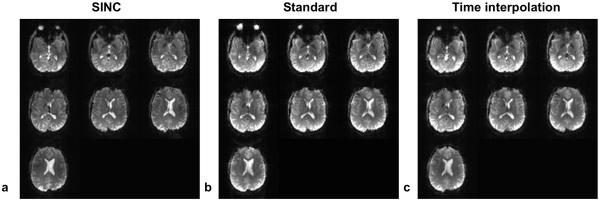
This figure shows multiple brain slices from an EPI sequence using three different sets of RF pulses for the comparison of signal recovery on Subject C. The signal loss in Fig. 10a has been successfully recovered in Figs. 10b and 10c. Similar results are seen in all other subjects.
DISCUSSION
In this article, we have successfully presented a novel excitation strategy to recover the susceptibility-induced signal loss at multiple slice locations via a through-plane phase precompensation method that takes advantage of parallel transmission techniques. Our results demonstrate for the first time that 3DTRF in conjunction with parallel transmission technique is an effective means to compensate for through plane signal loss at multiple slice locations during UHF fMRI studies. The article focuses on the proof-of-concept study, which was carried out to demonstrate the feasibility of combing PTX and 3DTRF for multi-slice studies at 7T. There are still some remaining issues. For example, we realize that the improvement of EPI study is modest, however, we have not fully understood the rationale behind it. At present, we believe that EPI needs more compensated work to do or the ghosting effects of fast imaging overwhelmed the signal recovery.
The use of 3DTRF as a means to correct for through plane signal loss during fMRI studies, as advocated by Stenger et al., has previously suffered from practical limitations stemming from the long RF pulse durations and the ad-hoc estimation of the distribution and size of the target phase pre-compensation pattern. We have shown that the information contained on the subject’s field map can be used effectively to provide the required phase pre-compensation information on a pixel-by-pixel basis. Because the calculation of the target pattern at one slice is completely independent from that in the other slices, the required computational time can be reduced significantly through the use of parallel computing techniques. We have, in fact, made extensive use of this fact in order to achieve the computational times reported here. It is important to note, that these computational times can be further improved through the use of faster computational code instead of the MATLAB environment. Consequently, the process of calculating phase pre-compensation pulses could be easily integrated into the calibration procedures of dedicated fMRI sequences in the very near future.
The results shown above also document that the use of a three-dimensional encoding matrix also imposes an implicit consistency in the results obtained for the RF pulses to be used for each slice. In other words, the fact the same encoding matrix is used for all slices implicitly ensures that the solution for the RF pulses will vary smoothly from one slice location to the next.
Though the proposed method is desirable in terms of excitation quality, it is multi-slice RF pulse design and thus computationally complex and the computational burden of this complexity increases with the volume size and sampling raster. As previously discussed, the finer time raster led to the best results because of its ability to accommodate for larger gradient strengths without introducing additional aliasing artifacts. This advantage needs to be weighed carefully during practical implementation due to the nearly 50% increase in computational time. However, with the use of Graphics Processing Units (GPU), like those found on consumer-grade computational hardware, these concerns might become negligible in the near future (25,26).
CONCLUSIONS
We have demonstrated an effective approach for simultaneous, multi-slice, susceptibility-induced signal loss recovery in T2* weighted imaging at ultra high field. Our results demonstrate that the level of signal recovery can be customized on a subject-by-subject basis through the acquisition of RF and main field homogeneity maps and RF pulse calculation. The relatively short computational time required by this approach (5 mins) makes it suitable for routine use and can, therefore, pave the way for the widespread use of PTX 3DTRF as part of routine neuroimaging studies at ultra high field.
Highlights.
-
◀
Propose novel RF pulse design by combining 3DTRF method with parallel transmission.
-
◀
Extend pulse design strategy to multi-slice excitation with parallel computation.
-
◀
Advanced PTX 3DTRF shows better performance than standard but expensive computation.
-
◀
PTX 3DTRF presents efficient signal recovery at multiple locations during UHF fMRI.
Footnotes
Publisher's Disclaimer: This is a PDF file of an unedited manuscript that has been accepted for publication. As a service to our customers we are providing this early version of the manuscript. The manuscript will undergo copyediting, typesetting, and review of the resulting proof before it is published in its final citable form. Please note that during the production process errors may be discovered which could affect the content, and all legal disclaimers that apply to the journal pertain.
REFERENCES
- [1].Hoult D, Richards R. The signal to noise ratio of the nuclear magnetic resonance experiment. J Magn Reson. 1976;24:71–85. doi: 10.1016/j.jmr.2011.09.018. [DOI] [PubMed] [Google Scholar]
- [2].Lipschutz B, Friston KJ, Ashburner J, Turner R, Price CJ. Assessing study-specific regional variations in fMRI signal. Neuroimage. 2001;13:392–398. doi: 10.1006/nimg.2000.0687. [DOI] [PubMed] [Google Scholar]
- [3].Ogawa S, Tank DW, Menon R, Ellerman JM, Kim S-G, Merkle H, Ugurbil K. Intrinsic signal changes accompanying sensory stimulation: functional brain mapping with magnetic resonance imaging. Proc Natl Acad Sci USA. 1992;89:5951–5955. doi: 10.1073/pnas.89.13.5951. [DOI] [PMC free article] [PubMed] [Google Scholar]
- [4].Ogawa S, Menon RS, Tank DW, Kim S-G, Merkle H, Ellerman JM, Ugurbil K. Functional brain mapping by blood oxygenation level dependent contrast magnetic resonance imaging. Biophys J. 1993;64:803–812. doi: 10.1016/S0006-3495(93)81441-3. [DOI] [PMC free article] [PubMed] [Google Scholar]
- [5].Chen NK, Dickey CC, Yoo SS, Guttmann CR, Panych LP. Selection of voxel size and slice orientation for fMRI in the presence of susceptibility field gradients: application to imaging of the amygdala. Neuroimage. 2003;19(3):817–825. doi: 10.1016/s1053-8119(03)00091-0. [DOI] [PubMed] [Google Scholar]
- [6].Haacke EM, Tkach JA, Parrish TB. Reduction of T2 dephasing in gradient field-echo imaging. Radiology. 1989 Feb;170(2):457–462. doi: 10.1148/radiology.170.2.2911669. [DOI] [PubMed] [Google Scholar]
- [7].Hsu JJ, Glover GH. Mitigation of susceptibility-induced signal loss in neuroimaging using localized shim coils. Magn Reson Med. 2005;53(2):243–248. doi: 10.1002/mrm.20365. [DOI] [PubMed] [Google Scholar]
- [8].Wong EC, Mazaheri Y. Shimming of the inferior frontal cortex using an external local shim coil; Proceedings of the 12th Annual Meeting of ISMRM; Kyoto. 2004.p. 520. [Google Scholar]
- [9].Constable R, Spencer D. Composite image formation in z shimmed functional MR imaging. Magn Reson Med. 1999;42:110–117. doi: 10.1002/(sici)1522-2594(199907)42:1<110::aid-mrm15>3.0.co;2-3. [DOI] [PubMed] [Google Scholar]
- [10].Glover GH. 3D z-shim method for reduction of susceptibility effects in BOLD fMRI. Magn Reson Med. 1999;42:290–299. doi: 10.1002/(sici)1522-2594(199908)42:2<290::aid-mrm11>3.0.co;2-n. [DOI] [PubMed] [Google Scholar]
- [11].Heberlein KA, Hu X. Simultaneous acquisition of gradient-echo and asymmetric spin-echo for single-shot z-shim: Z-SAGA. Magn Reson Med. 2004;51(1):212–216. doi: 10.1002/mrm.10680. [DOI] [PubMed] [Google Scholar]
- [12].Song AW. Single-shot EPI with signal recovery from the susceptibility-induced losses. Magn Reson Med. 2001;46:407–411. doi: 10.1002/mrm.1205. [DOI] [PubMed] [Google Scholar]
- [13].Stenger VA, Boada FE, Noll DC. Three-dimensional tailored RF pulses for the reduction of susceptibility artifacts in T2*weighted functional MRI. Magn Reson Med. 2000;44:525–531. doi: 10.1002/1522-2594(200010)44:4<525::aid-mrm5>3.0.co;2-l. [DOI] [PMC free article] [PubMed] [Google Scholar]
- [14].Yip CY, Fessler JA, Noll DC. Advanced three-dimensional tailored RF pulses for signal recovery in T2* weighted functional magnetic resonance imaging. Magn Reson Med. 2006;56:1050–1059. doi: 10.1002/mrm.21048. [DOI] [PubMed] [Google Scholar]
- [15].Yip CY, Yoon D, Olafsson V, Lee S, Grissom WA, Fessler, Noll DC. Spectral-spatial pulse design for through-plane phase precompensatory slice selection in T2*-weighted functional MRI. Magn Reson Med. 2009;61:1137–1147. doi: 10.1002/mrm.21938. [DOI] [PMC free article] [PubMed] [Google Scholar]
- [16].Yang C, Deng W, Alagappan V, Wald LL, Stenger VA. Four-dimensional spectral-spatial RF pulses for simultaneous correction of B1+ inhomogeneity and susceptibility artifacts in T2*weighted MRI. Magn Reson Med. 2010;64:1–8. doi: 10.1002/mrm.22471. [DOI] [PMC free article] [PubMed] [Google Scholar]
- [17].Katscher U, Bornert P, Leussler C, van den Brink JS. Transmit SENSE. Magn Reson Med. 2003;49:144–150. doi: 10.1002/mrm.10353. [DOI] [PubMed] [Google Scholar]
- [18].Zhu Y. Parallel excitation with array of transmit coils. Magn Reson Med. 2004;51:775–784. doi: 10.1002/mrm.20011. [DOI] [PubMed] [Google Scholar]
- [19].Grissom W, Yip CY, Zhang Z, Stenger VA, Fessler JA, Noll DC. Spatial domain method for the design of RF pulses in multicoil parallel excitation. Magn Reson Med. 2006;56:620–629. doi: 10.1002/mrm.20978. [DOI] [PubMed] [Google Scholar]
- [20].Grissom W, Yip CY, Wright SM, Fessler JA, Noll DC. Additive angle method for fast large tip angle RF pulse design in parallel excitation. Magn Reson Med. 2008;59:779–787. doi: 10.1002/mrm.21510. [DOI] [PubMed] [Google Scholar]
- [21].Zheng H, Zhao T, Qian Y, Ibrahim TS, Boada FE. Improved large tip angle parallel transmission pulse design through a perturbation analysis of the Bloch Equation. Magn. Reson. Med. 2011;66:687–696. doi: 10.1002/mrm.22827. [DOI] [PMC free article] [PubMed] [Google Scholar]
- [22].Pauly J, Nishimura D, Macovski A. A k-space analysis of small tip angle excitation. J Magn Reson. 1989;81:43–56. doi: 10.1016/j.jmr.2011.09.023. [DOI] [PubMed] [Google Scholar]
- [23].Zhao T, Zheng H, DeFranco A, Ibrahim TS, Qian Y, Boada FE. A fast B1 mapping method for transmit/receive coils for parallel transmit (PTX) applications; Proceedings of the 18th Annual Meeting of ISMRM; Stockholm, Sweden. 2010; Abstract 4927. [Google Scholar]
- [24].Saekho S, Yip CP, Noll DC, Boada FE, Stenger VA. A fast-kz 3D tailored RF pulse for reduced B1 inhomogeneity. Magn Reson Med. 2006;55:719–724. doi: 10.1002/mrm.20840. [DOI] [PMC free article] [PubMed] [Google Scholar]
- [25].Lee S-K, Xu D, Lechner SM, Vogel MW. Bloch Simulation Acceleration for fast pulse design in parallel transmit; Proceedings of the 18th Annual Meeting of ISMRM; Stockholm, Sweden. 2010; Abstract 4927. [Google Scholar]
- [26].Deng W, Yang C, Stenger VA. Accelerated multidimensional radiofrequency pulse design for parallel transmission using concurrent computation on multiple graphics processing units. Magn Reson Med. 2011;65:363–369. doi: 10.1002/mrm.22690. [DOI] [PMC free article] [PubMed] [Google Scholar]
- [27].Jankiewicz M, Zeng H, Moore JE, Anderson AW, Avison MJ, Welch EB, Gore JC. Practical considerations for the design of sparse spokes pulses. J Magn Reson. 2010;203:294–304. doi: 10.1016/j.jmr.2010.01.012. [DOI] [PMC free article] [PubMed] [Google Scholar]


