Abstract
This review describes homogeneous and heterogeneous catalytic reduction of dioxygen with metal complexes focusing on the catalytic two-electron reduction of dioxygen to produce hydrogen peroxide. Whether two-electron reduction of dioxygen to produce hydrogen peroxide or four-electron O2-reduction to produce water occurs depends on the types of metals and ligands that are utilized. Those factors controlling the two processes are discussed in terms of metal-oxygen intermediates involved in the catalysis. Metal complexes acting as catalysts for selective two-electron reduction of oxygen can be utilized as metal complex-modified electrodes in the electrocatalytic reduction to produce hydrogen peroxide. Hydrogen peroxide thus produced can be used as a fuel in a hydrogen peroxide fuel cell. A hydrogen peroxide fuel cell can be operated with a one-compartment structure without a membrane, which is certainly more promising for the development of low-cost fuel cells as compared with two compartment hydrogen fuel cells that require membranes. Hydrogen peroxide is regarded as an environmentally benign energy carrier because it can be produced by the electrocatalytic two-electron reduction of O2, which is abundant in air, using solar cells; the hydrogen peroxide thus produced could then be readily stored and then used as needed to generate electricity through the use of hydrogen peroxide fuel cells.
1. Introduction
The rapid consumption of fossil fuel is expected to cause unacceptable environmental problems such as the greenhouse effect by CO2 emission, which may lead to disastrous climatic consequences in the near future [1]. Even if climate change, such as that due to global warming, turns out to be a less than expected important problem, we are certainly on the verge of running out of fossil fuels by the end of 21st century, because the consumption rate of fossil fuel is expected to increase further by worldwide rapid population and economic growth, particularly in the developing countries [2]. Thus, renewable and clean energy resources are urgently required in order to solve global energy and environmental issues. Among renewable energy resources, solar energy is by far the largest exploitable resource [3–8]. Of course, solar energy has been utilized for ages in photosynthesis, leading to accumulated fossil fuel which we have been using so rapidly. It is therefore quite important for us to obtain sustainable solar fuels such as hydrogen or others [3–10].
Hydrogen is a clean energy source for the future and it can be used to reduce the dependence on fossil fuels and the emissions of greenhouse gases in the long-term [11–14]. The important advantage of hydrogen is that carbon dioxide is not produced when hydrogen is burned to produce only water. Hydrogen should be ideally produced by splitting water using solar energy. However, the storage of hydrogen has been a difficult issue, because hydrogen is a gas having a low volumetric energy density. Tank systems have been employed, either for gaseous pressurized hydrogen or liquid hydrogen. However, high-pressure equipment and a large demand for energy for cryogenic purposes are involved. Other approaches, such as in the use of metal hydrides, carbon nanotubes, and metal–organic frameworks can store or liberate only low amounts of hydrogen and unfavorable high temperatures are required to release the stored hydrogen [15–19]. Thus, none of the existing processes for storage and carriage of hydrogen are environmentally benign.
On the other hand, hydrogen peroxide has merited significant attention, because H2O2 can oxidize various chemicals selectively to produce no waste chemicals but water [20–22]. Hydrogen peroxide can be an ideal energy carrier alternative to oil or hydrogen, because it can be used in a fuel cell leading to the generation of electricity [23]. Thus, a combination of hydrogen peroxide production by the electrocatalytic reduction of dioxygen in air with electrical power generated by a photovoltaic solar cell and power generation with a hydrogen peroxide fuel cell provides a sustainable solar fuel [24]. Currently H2O2 is mainly produced by the anthraquinone process, in which the hydroquinone in an organic solvent is oxidized by molecular oxygen to produce H2O2 and quinone. The quinone formed can then be reduced by hydrogen using Ni or Pd catalysts. Thus, H2O2 is produced by the reduction of oxygen with hydrogen. In recent years, more than 3.5 million metric tons of H2O2 are produced all over the world annually in recent years [25]. In this review, first we describe homogeneous vs. heterogeneous catalytic reduction of dioxygen with a variety of metal complexes and then we introduce recent development in the electrocatalytic production of H2O2 and hydrogen peroxide fuel cells.
2. Catalytic reduction of dioxygen with metal complexes
2.1. Cobalt porphyrins
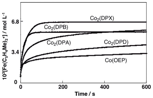
No reduction of O2 occurred by ferrocene derivatives such as 1,1′-dimethylferrocene [Fe(C5H4Me)2] in acetonitrile (MeCN) at 298 K [26], because electron transfer from Fe(C5H4Me)2 (Eox = 0.26 V vs. SCE) [27] to O2 (Ered = −0.86 V vs. SCE) [28] is highly endergonic. In the presence of HClO4 in MeCN solvent, however, O2 is slowly reduced by Fe(C5H4Me)2 to produce hydrogen peroxide (H2O2) via proton-coupled electron transfer from Fe(C5H4Me)2 to O2 [27]. Mononuclear cobalt complexes with macrobicyclic hexamine cage ligands have been reported to act as oxygen reduction catalysts for H2O2 production [29,30]. The addition of cobalt porphyrin monomers or dimers and HClO4 to air-saturated MeCN solutions containing ferrocene derivatives results in significantly accelerated O2-reduction. (Scheme 1) [31,32]. The stoichiometry of the oxidation of ferrocene derivatives by O2 in the presence of HClO4 (two- vs four-electron reduction of O2) was determined by the concentration of ferrocenium cations compared with the concentration of O2, when the concentration of O2 made to be much smaller [32]. When a monomer cobalt porphyrin such as 2,3,7,8,12,13,17,18-octaethyl-porphinato cobalt(II) [Co(OEP)] was employed as a catalyst, two equiv. of the ferrocenim cation ([Fe(C5H4Me)2]+) were produced from O2, using Fe(C5H4Me)2 in the presence of excess HClO4 in benzonitrile (PhCN) at 298 K as shown in Fig. 1 [32]. Thus, only two-electron reduction of O2 occurs and no further reduction occurs to produce more than two equiv. of Fe(C5H4Me)2+ [Eq (1)].
Scheme 1.

Fig. 1.
Time profiles of formation of Fe(C5H4Me)2+ monitored at 650 nm in electron transfer oxidation of Fe(C5H4Me)2 (1.0 × 10⁻¹ mol L−1) by O2 (1.7 × 10⁻³ mol L−1), catalyzed by Co2(DPX) (2.0 × 10⁻⁵ mol L−1), Co2(DPA) (2.0 × 10⁻⁵ mol L−1), Co2(DPB) (2.0 × 10⁻⁵ mol L−1), Co2(DPD) (2.0 × 10⁻⁵ mol L−1), and Co(OEP) (3.0 × 10⁻⁵ mol L−1) in the presence of HClO4 (2.0 × 10⁻² mol L−1) in PhCN at 298 K.
| (1) |
Confirmation that a stoichiometric amount of H2O2 was formed was carried out using iodometric measurements [31].
In contrast to the monomeric cobalt porphyrin, when a cofacial dicobalt porphyrin (Co2(DPX) in right column in Scheme 1) was employed as a catalyst, four equiv. of [Fe(C5H4Me)2]+ was produced in the catalytic reduction of O2 by Fe(C5H4Me)2 in the presence of HClO4 in PhCN at 298 K (Fig. 1) [Eq. (2)] [32]. Thus, the four-electron reduction of O2 occurs here efficiently. It was separately confirmed that no H2O2 was formed in during this process [32].
| (2) |
The other cofacial dicobalt porphyrins [Co2(DPA), Co2(DPB) and Co2(DPD) in the left column of Scheme 1] also catalyze the reduction of O2 by Fe(C5H4Me)2, but the amount of Fe(C5H4Me)2+ formed is less than four equiv. based on the amount of O2 (Fig. 1) [32]. This indicates that the clean four-electron reduction of O2 by Fe(C5H4Me)2 occurs only in the case of Co2(DPX) and other dicobalt porphyrins as catalysts lead to a mixture of processes, i.e., involving both two- and four-electron stoichiometries.
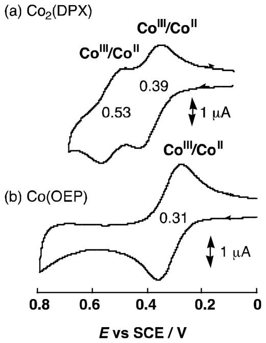
The cyclic voltammograms of Co(OEP) and [Co2(DPX)] are compared in Fig. 2, where the one-electron reduction potential of Co(OEP) is determined to be 0.31 V corresponding to the Co(II)/Co(III) couple, whereas the Co(II)/Co(III) couple for [Co2(DPX)] is split into two one-electron redox waves at 0.53, 0.39 V (vs. SCE) [32]. This indicates that two Co ions are interacting with each other in [Co2(DPX)].
Fig. 2.
Cyclic voltammograms of (a) Co2(DPX) and (b) Co(OEP) (1.0 × 10⁻³ mol L−1) in PhCN containing 0.1 mol L−1 TBAP; scan rate 100 mV s−1.
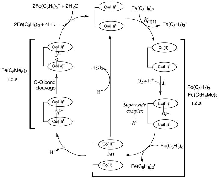
The catalytic cycle of the two-electron reduction of O2 by Fe(C5HMe)2 in the presence an acid in PhCN is shown in Scheme 2 [32]. The initial electron transfer from Fe(C5H4Me)2 to Co(III)OEP+ is thermodynamically feasible judging from the one-electron oxidation potentials known for the compounds in question: Fe(C5H4Me)2 (Eox = 0.26 V vs. SCE) and Co(OEP)+ (Ered = 0.31 V vs. SCE in Fig. 2). Indeed, electron transfer from Fe(C5HMe)2 to Co(OEP)+ occurs and this is followed by the subsequent fast electron transfer from Co(II)OEP to O2 in the presence of an acid to produce the hydroperoxyl species Co(III)(OEP)O2H+, which is further oxidized by Fe(C5H5)2 in the presence of an acid to produce H2O2, accompanied by regeneration of Co(III)OEP+. The initial electron transfer is the rate-determining step in the catalytic cycle, when the catalytic rate is given by Eq. (3) [32]. In such a case the catalytic rate
Scheme 2.
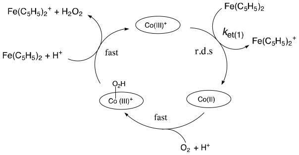
| (3) |
does not depend on the concentration of O2 or an acid. In addition, the observed second-order rate constant is twice that of the rate constant (ket) for the initial electron transfer from Fe(C5HMe)2 to Co(III)OEP+ (kobs = 2ket) [32].
The same catalytic scheme can be applied for the selective two-electron reduction of O2 by ferrocene derivatives with other monomeric metalloporphyrin complexes: CoTPP+, FeTPP+ and MnTPP+ (TPP2− = tetraphenylporphyrin dianion) [31]. The rate constants of the rate-determining electron transfer from ferrocene derivatives to CoTPP+, FeTPP+ and MnTPP+ can be evaluated using the Marcus theory of outer-sphere electron transfer [33]. The Marcus relation provides that the rate constant for electron transfer from an electron donor (1) to an electron acceptor (2), k12, is given by Eq. (4), where k11 and k22 are the rate constants for self-exchange or each component, 1 and 2, K12 is the electron-transfer equilibrium constant, which is obtained from the one-electron oxidation potential of 1 and the one-electron reduction potential of 2. The parameter f in Eq. (4) is given by Eq. (5), where Z is the frequency factor (1 × 10¹¹ mol−1 L s−1) [33]. The k11 value of ferrocene is reported to be 5.3 × 10⁶ mol−1 L s−1 [34], and the k22 values of Co, Fe and Mn porphyrins are reported to be 20 [35], 1 × 10⁹ [36], 3.2 × 10³ mol−1 L s−1 [37], respectively. The results are that based on Eqs. (4) and (5) and using the k11 and k22 values, the rate constants for electron transfer from ferrocene derivatives to CoTPP+, FeTPP+ and MnTPP+ agree well with the observed rate constants [31]. Such agreement strongly indicates electron transfer from ferrocene derivatives to metalloporphyrins occurs via an outer-sphere pathway.
| (4) |
| (5) |
The reason why only Co2(DPX) can act as a catalyst for the selective four-electron reduction of O2 (Fig. 2) can be understood by comparing the distances between porphyrin moieties in the cofacial porphyrins complexes, based on data from reported crystal structures of Co2(DPB) [38], Co2(DPA) [39], Co2(DPX) [40,41], and Co2(DPD)(2MeOH) [40,41] (Fig. 3). The metal-metal separations in Co2(DPA) (0.453 nm) and Co2(DPX) (0.458 nm) are virtually the same. However, the xanthene spacer of Co2(DPX) is more flexible than the anthracene spacer of Co2(DPA) and thereby more suitable for the strong binding between two cobalt nuclei and O2. The metal-metal separation in Co2(DPB) (0.373 nm) may be too short, whereas the separation in Co2(DPD)(2MeOH) (0.862 nm) is too long to bind O2 between two cobalt nuclei. Thus, the interaction of two cobalt nuclei with an active form of oxygen seems essential for the four-electron reduction of O2. It is interesting to note that the Co-Co distance of Co2(DPX) (0.458 nm) is nearly the same as the Co-Co distance of a dicobalt(III) μ2-η1:η1-peroxo complex with the tetrapodal pentaamine ligand 2,6-bis(1′,3′-diamino-2′-methylprop-2′yl)pyridine (0.450 nm), which was structurally characterized by X-ray crystallographic analysis [42]. The Co-Co distances in dicobalt bis-μ-oxo complexes, {[Me2NN]Co}2(μ-O)2 (Me2NN = β-diketiminato) [43] and {[TpMe3]Co}2(μ-O)2 (TpMe3 = hydrotris(3,5-dimethyl-4-methylpyrazolyl)borate), were reported to be 0.3067 nm and 0.2724 nm, respectively [44]. The Co-Co distance of a biscobalt peroxo complex, [Co3+(μ,η1:η2-O2)(oxapyme)Co3+]2+ (oxapyme(H)2 = 2-(bis-pyridin-2-ylmethyl-amino)-N-[2-(5-{2-[2-(methyl-pyridin-2-ylmethyl-amino)]-phenyl}-[1,3,4]-oxadiazol-2-yl)-phenyl]-acetamide), in which one of the oxygen atoms bridges the two metals and is sideways bonded to one of the metals, was reported to be 0.3339 nm [45]. Thus, the biscobalt(III) peroxo complex responsible for the catalytic four-electron reduction of O2 may have the μ2-η1:η1 bonding mode rather than bis-μ-oxo or μ,η1:η2 bonding modes.
Fig. 3.
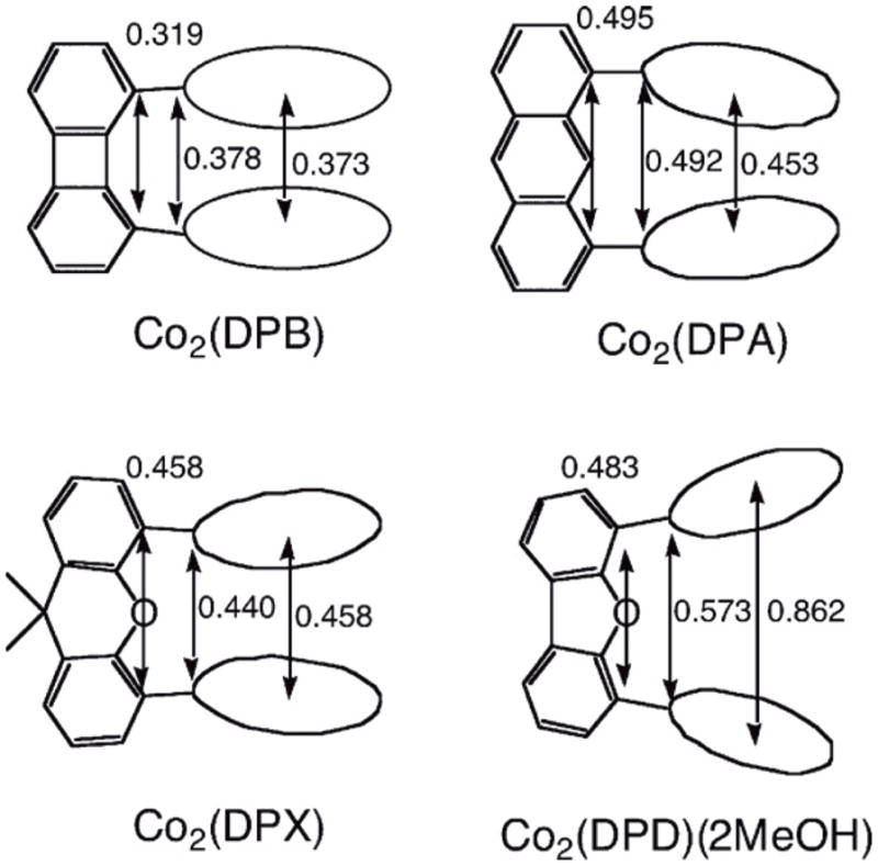
Selected distance (nm) in Co2(DPB) [38], Co2(DPA) [39], Co2(DPX) [40,41], and Co2(DPD)(2MeOH) [40,41].
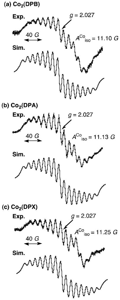
The proposed mechanism of four-electron reduction of O2 by ferrocene derivatives is summarized as shown in Scheme 3. The initial two-electron reduction of the Co(III)2 complex by ferrocene derivatives gives the Co(II)2 complex, which reacts with O2 to produce the μ-peroxo Co(III)-O2-Co(III) complex via the intermediacy of a μ-superoxo complex (not shown). The μ-superoxo species in these cofacial dicobalt porphyrins could be separately produced by the reactions of cofacial dicobalt(II) porphyrins with O2 in the presence of a bulky base (1-tert-butyl-5-phenylimidazole) and the subsequent one-electron oxidation of the resulting peroxo species by iodine [32]. The EPR spectra of the μ-superoxo species exhibit superhyperfine structure due to two equiv. cobalt nuclei (Fig. 4) [32]. The heterolytic O-O-bond cleavage of the Co(III)-O2-Co(III) complex affords the high valent Co(IV)-oxo species which is reduced by ferrocene derivatives in the presence of protons to yield H2O (Scheme 3). Alternatively the homolytic O-O bond cleavage affords two Co(III)-oxyl species which are reduced by ferrocene derivatives to H2O in the presence of an acid. In each case, the O-O bond cleavage of the Co(III)-O2-Co(III) complex leads to the four-electron reduction of O2 (Scheme 3) whereas if protonation first takes place then overall two-electron reduction of O2 to produce H2O2 would occur. The stronger the binding between two cobalt nuclei and oxygen in the Co(III)-O2-Co(III) complex, the weaker is the O-O bond, and the faster is the rate of O-O bond cleavage. This seems to be the case for Co2(DPX), which has the largest superhyperfine coupling constant of the μ-superoxo species (Fig. 4), indicating greater interaction of the superoxide moiety spin with the cobalt(III) centers, and this acts as the most efficient catalyst for the selective four-electron reduction of O2 by ferrocene derivatives (Fig. 1).
Scheme 3.
Fig. 4.
EPR spectra of the μ-superoxo complex (~10−3 mol L−1) produced by adding iodine (~10−3 mol L−1) to an air-saturated PhCN solution and ESR simulation of (a) Co2(DPB), (b) Co2(DPA) and (c) Co2(DPX) in the presence of 1-tert-butyl-5-phenylimidazole (5 × 10⁻³ mol L−1) at 298 K [32].
Detailed kinetic investigations and analyses on the rate of formation of Fe(C5H5)2+ in the Co2(DPX)-catalyzed electron transfer oxidation of Fe(C5H5)2 by O2 in the presence of HClO4 revealed that the rate-determining step (Scheme 3) is a proton-coupled electron transfer from Co(III)Co(II)(DPX)+ to O2 following initial electron transfer from Fe(C5H5)2 to Co(III)2(DPX)2+ [32]. In this case the rate of formation of Fe(C5H5)+ is proportional to the concentrations of Co(III)2(DPX)2+, O2 and HClO4. When Fe(C5H5)2 is replaced by a much stronger reductant, that is Fe(C5Me5)2 (Fc*) however, the kinetics of formation of Fc*+ change drastically from first-order kinetics in the case of Fe(C5H5)2 to zero-order kinetics, because the rate-determining step in the is changed to an O-O bond cleavage step in the Co(III)-O2-Co(III) complex [32]. In this situation, the rate remains constant irrespective of change in concentrations of O2 and HClO4. The O-O bond cleavage rate has been determined as 320 s−1 [32].
The electrocatalytic reduction of O2 was examined using Co2(DPX) and Co2(DPD), which were adsorbed onto an electrode surface by means of a dip-coating procedure [46]. Rotating Pt ring-disk voltammograms for reduction of O2 at pyrolytic graphite disks coated with Co2(DPX) and Co2(DPD) revealed the catalytic four-electron reduction of O2 with 72% and 80% selectivity, respectively [46]. The partial formation of H2O2 was clearly detected by the rotating ring current [46]. Thus, the selectivity for the electrocatalytic four-electron reduction of O2 is lower than the selectivity in the homogeneous system (Fig. 1). Such differences in selectivity for homogeneous versus heterogeneous catalysis of O2-reducing systems will be discussed further, in the next section.
2.2. Biscobalt porphyrin-corrole complexes
The same selectivity with regard to two-electron vs. four-electron reduction of O2 by Fe(C5H4Me)2 depending on the type of linkage (Y) of biscobalt complexes (Fig. 1) was observed for the catalytic reduction of O2 with cofacial biscobalt porphyrin-corrole complexes (Chart 1) in the presence of HClO4 in PhCN [47]. When 1, 2, 4 or 5 is used as a catalyst, two-electron reduction of O2 by Fe(C5H4Me)2 occurred efficiently in the presence of HClO4 in PhCN, whereas the four-electron reduction of O2 occurred when 3 or 6 was used as a catalyst as shown in Fig. 5 [47]. Thus, in this case as well, a suitable metal-metal separation with Y = 9,9-dimethylxanthene (X) is required to produce the μ-peroxo Co(III)-O22 −-Co(III) complex that is the key intermediate for the catalytic four-electron reduction of O2.
Chart 1.
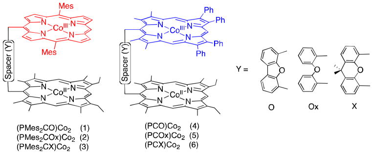
Structures of biscobalt porphyrin-corrole complexes.
Fig. 5.
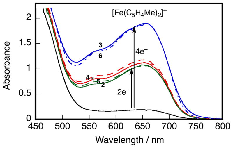
Visible absorption spectra changes in the catalytic reduction of O2 (1.7 × 10⁻³ mol L−1) by Fe(C5H4Me)2 (2.0 × 10⁻² mol L−1) in the presence of HClO4 (2.0 × 10⁻² mol L−1) and 1 – 6 (2.0 × 10⁻⁵ mol L−1) in PhCN at 298 K; 1 (red solid line), 2 (green solid line), 3 (blue solid line), 4 (red broken line), 5 (green broken line) and 6 (blue broken line). Black: in the absence of cobalt complex.
The catalysts 1–6 were also adsorbed onto a graphite disk by transferring aliquots of a solution in CHCl3 directly to the electrode surface followed by evaporation of the solvent as the case of Co2(DPX) and Co2(DPD) (vide supra) [46]. The biscobalt porphyrin–corrole complex-modified electrodes were used to examine the electrocatalytic properties in the presence of 1 mol L−1 HClO4 in PhCN [47]. The catalytic activity was determined by cyclic voltammetry as well as by rotating disk electrode voltammetry and the results are summarized in Table 1 [47]. All six complexes catalyze the electrocatalytic reduction of O2 at potentials close to their E1/2 values (Table 1). The average E1/2 value for the electroreduction of O2 at a rotating disk electrode coated with 1–3 is 0.32 V.
Table 1.
Electroreduction of dioxygen by adsorbed biscobalt porphyrin–corrole dyads in air-saturated 1.0 mol L−1 HClO4
| Bridge (Y) | (PMes2CY)Co2 (1–3)
|
(PCY)Co2 (4–6)
|
||||
|---|---|---|---|---|---|---|
| Epa | E1/2b | nc | Epa | E1/2b | nc | |
| O | 0.25 | 0.32 | 2.4 | 0.34 | 0.41 | 3.547 |
| Ox | 0.27 | 0.33 | 2.5 | 0.35 | 0.40 | 3.1 |
| X | 0.25 | 0.32 | 2.5 | 0.38 | 0.45 | 3.747 |
Peak potential of the dioxygen reduction wave (V vs. SCE).
Half-wave potential (V vs. SCE) for dioxygen reduction at rotating disk electrode (ω = 100 rpm).
Electrons consumed in the reduction of O2 as estimated from the slope of the Koutecky–Levich plots.
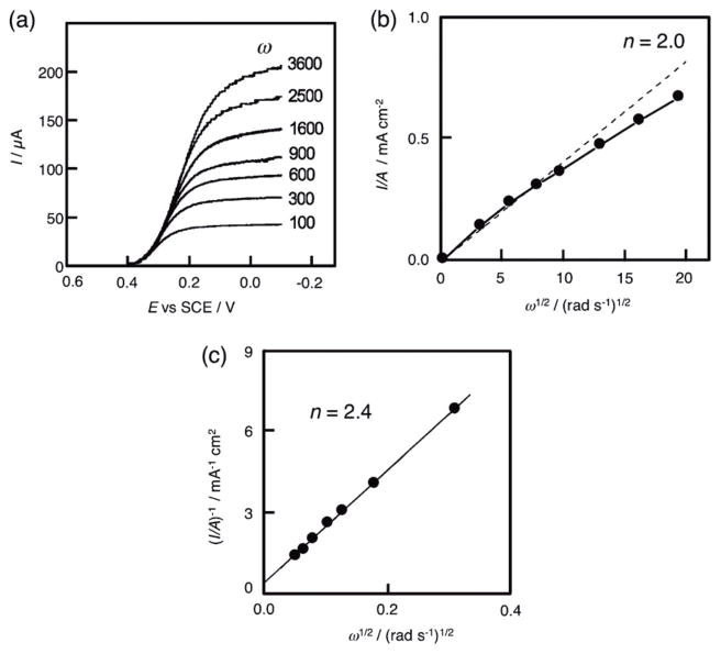
The number of electrons transferred during oxygen reduction was calculated from the magnitude of the steady-state limiting current values, which were taken at a fixed potential on the catalytic wave plateaus of the different current-voltage curves, as shown in Fig. 6a [47]. If mass transport alone controls the reduction of O2 at the 2-modified electrode, then the relationship between the limiting current and rotation rate obeys the Levich equation [Eq. (6)] [48,49]:
| (6) |
where n is the number of electrons transferred, F is the Faraday constant, A is the electrode area (cm2), v is the kinematic viscosity of the solution (cm2 s−1), D is the O2 diffusion constant (cm2 s−1), [O2] is bulk concentration of O2 (mol L−1), and ω is the rate of rotation (rad s−1). According to Eq. (6), the plot of the limiting current density I/A vs. ω1/2 gives a straight line intersecting the origin as shown in Fig. 6b. The deviation from the initial linearity suggests that the catalytic reaction is limited by kinetics, not by mass transport alone. In that case, the number of electrons transferred can be determined by using the Koutecky-Levich equation [Eq. (7)] [50,51]:
| (7) |
where k is the second-order rate constant of electron transfer (mol−1 L s−1), which limits the plateau current. The number of electrons transferred in the O2 electroreduction process involving complexes 1 – 3 ranges from 2.4 to 2.5 (Table 1 and Fig. 6c) [47]. This indicates that the electrocatalytic reduction of O2 by the biscobalt porphyrin–corrole complexes results in formation of H2O2 mainly via the two-electron reduction of O2 in the presence of HClO4. These values are different from the biscobalt porphyrin–corrole complexes 4 – 6 where n = 3.1 to 3.7 (Table 1). In the case of 6, O2 was mainly reduced to H2O via a four-electron and four-proton process [47].
Fig. 6.
Electrocatalytic reduction of O2 in 1 mol L−1 HClO4 at a rotating graphite disk electrode coated with (PMes2CO)Co2 1. (a) Values of the rotation rates of the electrode (w) are indicated on each curve. The disk potential was scanned at 5 mV s−1. (b) Levich plots of the plateau currents of (a) vs. (rotation rate)1/2. The dashed line refers to the theoretical curve expected for the diffusion-convection limited reduction of O2 by 2e−. (c) Koutecky-Levich plots of the reciprocal plateau currents vs. (rotation rates)−1/2. Supporting electrolyte: 1 mol L−1 HClO4 saturated with air.
The number of electrons transferred in the O2-electroreduction at the electrode process involving complexes 4 – 6 (Table 1 and Fig. 6) is different from that observed in the homogeneous phase in Fig. 4 except for the case of complex 6 (n = 3.7). This difference (Table 1), and similar variations observed for the biscobalt porphyrin complexes in homogeneous vs. heterogeneous solution (Fig. 1) may result from different coordination geometries of biscobalt complexes which may occur of their interactions with the surface material when they are adsorbed onto the graphite electrode. As already described, the selectivity for the four-electron reduction of O2 is quite sensitive to the Co-Co distance of biscobalt porphyrins (Fig. 3), thus an electrode surface induced small change in the nature of the proximity of each porphyrin moiety within a synthetic dyad, i.e., the biscobalt complexes, may result in significant changes in terms of the selectivity toward differing reduction processes.
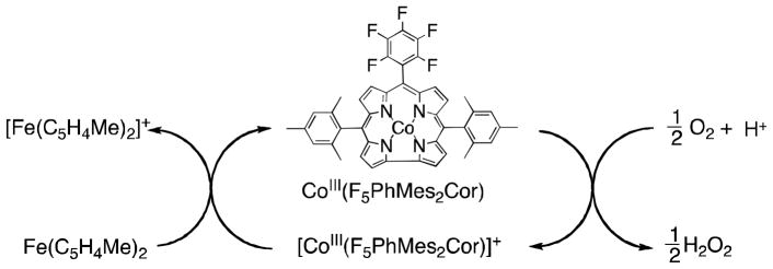
When a monomeric cobalt corrole ([10-pentafluorophenyl-5,15-dimesityl-corrole]cobalt complex, Co(F5PhMes2Cor), was employed as an electrocatalyst for the reduction of O2, the slope of the Koutecky-Levich plot shows that the catalytic electroreduction of O2 is a pure two-electron process to produce H2O2 [52]. The catalytic process employing Co(F5PhMes2Cor) was confirmed for the homogeneous phase using Fe(C5H4Me)2 as a reductant in PhCN solvent [52]. Electron transfer from Fe(C5H4Me)2 (Eox = 0.26 V vs. SCE) to [Co(F5PhMes2Cor)]+ (Ered = 0.38 V) [53] occurs efficiently to produce [Fe(C5H4Me)2]+ and Co(F5PhMes2Cor) [52]. The cobalt(III) corrole complex, Co(F5PhMes2Cor), can reduce O2 in the presence of HClO4. The site of electron transfer has been confirmed to be the corrole ligand, based on the finding by EPR spectroscopy of an observed g-value of 2.0032 for the singly oxidized cobalt corrole, that separately obtained by the chemical oxidation of Co(F5PhMes2Cor) with one equivalent of [Fe(bpy)3]3+ (bpy = 2,2′-bipyridine). This signal is characteristic of an organic radical; it is quite different from the large g-value (2.037) observed for cobalt(IV) porphyrin complexes. In contrast to the case of cobalt porphyrins (Scheme 2), the cobalt corrole complex acts as an effective catalyst in the two-electron reduction of O2 with HClO4 via the redox couple between the cobalt(III) corrole and the cobalt(III) corrole radical cation (Scheme 4).
Scheme 4.
2.3. Cytochrome c oxidase models
In the final step in the biological respiratory chain, the four-electron and four-proton reduction of O2 to H2O is efficiently catalyzed by the heme/copper (heme a3/CuB) heterodinuclear center in cytochrome c oxidases (CcO) (Fig. 7a) [54–56]. Biomimetic chemical modeling of the CcO active site has extensively been studied to provide not only the mechanistic insights into the four-electron and four-proton reduction of O2 but also as a blueprint for bioinspired fuel cells [56–62]. A number of heme a3/CuB synthetic analogues have been developed to mimic the coordination environment of the heme a3/CuB bimetallic center in CcO [56–61]. The electrocatalytic function of heme a3/CuB synthetic analogues has also been examined by using electrodes modified with the synthetic models to perform the catalytic four-electron and four-proton reduction of O2 [59–63]. However, the structure of synthetic models may be changed when they are adsorbed on an electrode surface (vide supra). In addition, the solid supported state employed for such studies has precluded any spectroscopic monitoring or intermediates detection. Thus, the catalytic reduction of O2 to water was examined using ferrocene derivatives as one-electron reductants and a heme/Cu functional model of CcO (6LFeCu, Fig. 7b) and its Cu-free version (6LFe, Fig. 7c) as catalysts in homogeneous solutions. [64]. The detailed kinetic analysis together with spectroscopic detection of reactive intermediates has provided new mechanistic insights into the O–O reductive cleavage process as described here [64].
Fig. 7.
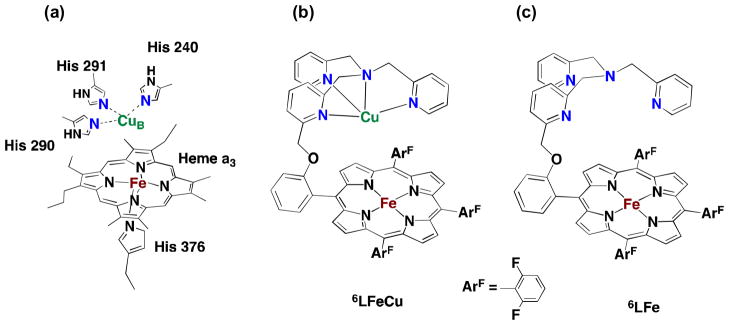
(a) X-ray structures of the fully reduced bimetallic heme a3/CuB center in CcO from bovine heart (FeII···CuI = 0.519 nm), (b) heme/Cu synthetic model for CcO (6LFeCu), (c) Cu-free version of synthetic model for CcO (6LFe).
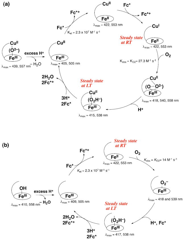
The catalytic mechanism for the four-electron and four-proton reduction of O2 by decamethylferrocene (Fc*) with 6LFeCu and 6LFe in acetone is summarized in Scheme 5a and Scheme 5b, respectively. In the presence of acid, [6LFeIII-O-CuII]+ is converted to [6LFeIIICuII]3+ by releasing water and the catalytic cycle starts via a fast reduction of the heme and then the Cu to generate the reduced complex [6LFeIICuI]+. Then O2 binds to [6LFeIICuI]+, and this is followed by rapid protonation affording the Fe-hydroperoxo complex {6LFeIII-OOH CuII}2+. Reductive O-O bond cleavage is followed by further rapid reduction to produce H2O accompanied by regeneration of [6LFeIIICuII]3+. The rate of formation of Fc* was zero-order and the zero-order rate constant increased proportionally with increasing the catalyst concentration, but the zero-order rate constant remained constant with variation of concentrations of TFA and O2 at 213 K [64]. This unusual kinetics indicates that the rate-determining step is a process which does not involve reactions with Fc*, H+, O2. Such a reaction is the O-O bond cleavage in {6LFeIII-OOH CuII}2+, followed by rapid electron transfer to complete the four-electron and four-proton reduction of O2. This is confirmed by the steady-state observation of {6LFeIII-OOH CuII}2+ (λmax = 415, 538 nm) during the catalytic reduction of O2 by Fc* with 6LFeCu at 213 K. {6LFeIII-OOH CuII}2+ was independently generated at low temperature (193 K) by the addition of an excess of TFA to the previously well characterized peroxo complex [6LFeIII-(O22−)-CuII]+ [65].
Scheme 5.
In the case of the Cu-free version 6LFe (Scheme 5b) as well, the rate of formation of Fc* was zero-order and the zero-order rate constant increased proportionally with increasing the catalyst concentration, but the zero-order rate constant remained constant with variation of concentrations of TFA and O2 at 213 K [64]. This again indicates that the rate-determining step in the catalytic cycle is the O-O bond cleavage of 6LFeIII-OOH. Surprisingly the bond cleavage rate of 6LFeIII-OOH is the same as that of {6LFeIII-OOH CuII}2+. This suggests that the Cu is not bound to the FeIII-OOH moiety in {6LFeIII-OOH CuII}2+.
This rate-determining step found to occur at 213 K is changed to be the process of O2-binding to [6LFeIICuI]+ at 298 K when the zero-order rate constant increases proportionally with increasing concentration of O2 [64]. The change in the rate-determining step at 298 K was confirmed by the change in the steady-state species identified to be {6LFeIII-OOH CuII}2+ at 213 K instead to [6LFeIICuI]+ (λmax = 422 nm) at 298 K. In contrast to the case at 213 K, however, the O2-binding rate at 298 K to [6LFeIICuI]+ is significantly faster than that to 6LFeII [64]. This result suggests that the role of the Cu in 6LFeCu, at ambient temperature, is to assist the heme and lead to faster O2-binding during the catalytic cycle.
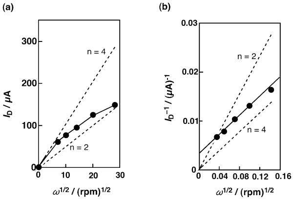
The electrocatalytic reduction of O2 was examined using an edge plane pyrolytic graphite (EPG) disk shape electrode, which was modified with 6LFeCu [66]. The modified EPG electrode was prepared by transferring an MeCN solution of [6LFeIICuI]+ on the EPG surface and allowing the solvent to evaporate in an argon atmosphere giving a dried surface [66]. Levich and Koutecky-Levich plots [Eqs. (6) and (7)] are shown in Fig. 8a and 8b, respectively [66]. The dashed lines were obtained from the calculated diffusion-convection controlled currents based on the Levich equation assuming the number of electrons for O2 reduction as two or four. The open circles were from the measured plateau currents and they were higher than those with the two-electron reduction. The deviation from linearity of the four-electron transfer plot suggests that the catalytic reaction is limited by kinetics in addition to the mass-transfer process. In the Koutecky-Levich plot in Fig. 8b obtained from the data in Fig. 8a, the measured values (open circles) were parallel to the line of four-electron reduction. This indicates that the adsorbed complex [6LFeIICuI]+ catalyzed the four-electron reduction of O2 to H2O as is the case in the homogeneous solution (vide supra). The four-electron reduction of O2 to H2O was confirmed by using rotating EPG disk-platinum ring electrodes to measure the fraction of O2, which was reduced to H2O, rather than to H2O2. With adsorbed [6LFeIICuI]+, a small anodic ring plateau curve was observed during the reduction of O2 at the EPG disk electrode and it was found that most O2 (85 %) was reduced to H2O [66].
Fig. 8.
(a) Levich plot from the plateau currents in plot of current vs. (rotation rate)1/2. (b) Koutecky-Levich plot from the plateau currents in Fig. 2 [(current)−1 vs. (rotation rate)1/2]. The dashed lines in (a) and (b) were obtained from the calculated diffusion-convection controlled currents for the reduction of O2 assuming the number of electrons as two and four.
2.4. Cu complexes
There has been considerable interest in the use of copper in O2-reduction chemistry. One reason is the existence of copper containing enzymes which efficiently effect the four-electron four-proton reduction to water as part of their function. These include so-called multi-copper oxidases (MCO’s) [67–70] wherein an array of copper ions arranged in a tricopper cluster plus a separate but electronically linked copper ion, the latter which effects one-electron oxidations (at a time) of biological substrates, e.g., ascorbate, phenols, diamines, Fe(II) and Cu(I). Such studies have lead to the use of such enzymes, supported on electrodes, to carry out electrocatalytic dioxygen reductions in fact having very high activity [71–73].
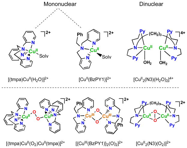
However, the existence of MCO’s and particularly inspired by the existence of dicopper enzymes which are blood oxygen carriers in mollusks and arthropods (i.e., hemocyanins) [71, 73], or biologically ubiquitous tyrosinases which ortho-hydroxylate phenols giving catechols and/or quinone products which are converted to melanin pigments [70, 72], has led synthetic bioinorganic chemists to vigorously pursue the study of dioxygen binding and reactivity with discrete copper ion complexes [74–78]. Such investigations have revealed many new fundamental aspects in the field, including the uncovering of a number of now very well defined copper(I)-O2 derived complexes, existing in different structural forms, although all possessing the Cu2-O2 core. Four structural types are known [75, 77, 78], and the generation of one or another depends primarily on the nature of the nitrogenous ligand employed, and the compounds formed can arise from differing mononuclear copper-ligand complexes or those derived from the use of binucleating ligands. Some of these are shown in Fig. 9, along with diagrams of the core peroxo-dicopper(II) or bis-μ-oxo-dicopper(III) structures.
Fig. 9.
Complexes used as catalysts for the solution four-electron four-proton reduction of O2 by ferrocene derivatives and the copper(I)-dioxygen derived complex intermediates known to form during the course of reaction. See text for discussions.
While the activity of supporting discrete ligand-metal complexes on electrode surfaces is an active area of research, including for copper (see below), homogeneous catalytic O2-reduction using the complexes shown in Fig. 9 in water and/or organic solvents comes about when employing ferrocene derivatives as one-electron outer-sphere reductants and acids as proton sources [79, 80]. Electrocatalysis certainly has advantages, including the greater likelihood for practical application, however solution investigations enable kinetic and spectroscopic (e.g., UV-vis, EPR) monitoring of key steps during catalysis. This can and does provide for insights into mechanism, via the determination of the identity of intermediates and the order of reaction of a particular step with respect to electron and/or proton concentrations. Such information can provide for elaboration or altering of the catalyst complex ligand, so as to improve future performance.
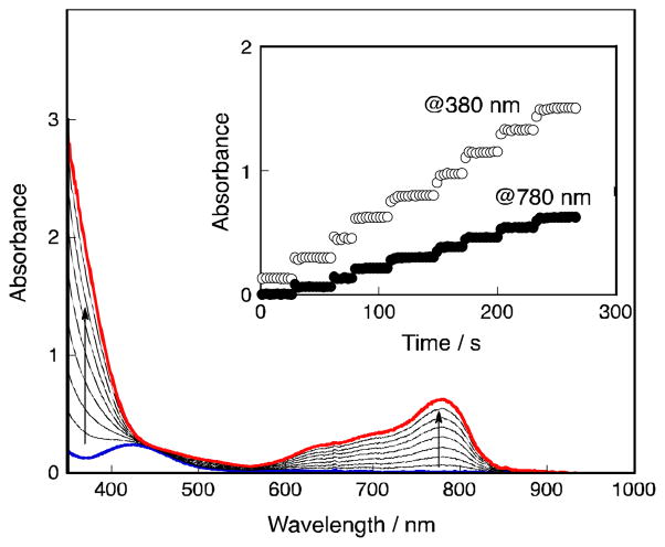
In fact, all of the Fig. 9 complexes can catalyze O2-reduction chemistry [79, 80]. First using Fc* and perchloric acid in acetone solutions, the catalytic 4e−/4H+ reduction of O2 to water with [(tmpa)CuII(H2O)]2+ was examined by following detailed spectroscopic and kinetic monitoring [79]. The mechanism derived is shown in Scheme 6 [79]. The addition of a catalytic amount of [(tmpa)CuII(H2O)]2+ to an O2-saturated acetone solution of Fc* and HClO4 resulted in the efficient oxidation of Fc* by O2 to afford ferrocenium cation (Fc*+). Fig. 10 shows the spectral changes observed for stepwise addition perchloric acid. For each time period of acid addition (see Fig. 10 Inset), the concentration of Fc*+ which was formed immediately (absorption increases at λmax = 380 and 780 nm) was the same as the mole-amount of added HClO4.
Scheme 6.

Fig. 10.
UV-vis spectral changes in four-electron reduction of O2 by Fc* (1.5 × 10⁻³ mol L−1) with [(tmpa)CuII(H2O)]2+ (9.0 × 10⁻⁵ mol L−1) in the presence of HClO4 in acetone at 298 K. The inset shows the changes in absorbance at 380 and 780 nm due to Fc*+ produced by stepwise addition of HClO4 (0.18 – 1.44 × 10⁻³ mol L−1) to an O2-saturated acetone solution ([O2] = 11 × 10−3 mol L−1) of Fc* and [(tmpa)CuII(H2O)]2+.
The production of water was confirmed by mass spectrometry when running reactions using 18O water. Two-electron O2-reduction chemistry could be ruled out since iodometric titration experiments yielded no detectable hydrogen peroxide. In the presence of limiting [O2], and excess Fc*, still only 4 equiv. Fc*+ was formed in the presence of 4 equiv. of HClO4. Thus, these experiments (and others) demonstrated the overall reaction stoichiometry, as catalyzed by [(tmpa)CuII(H2O)]2+, to be:
It has been demonstrated that the rate limiting step in the reaction cycle was reduction of [(tmpa)CuII(H2O)]2+ by Fc* [79]. Then, under conditions where Fc* and acid were depleted, stopped-flow kinetic measurements revealed the very rapid generation of the well known dioxygen adduct, peroxo complex [(tmpa)CuII(O2)CuII(tmpa)]2+ [75, 77–79] (Scheme 6). Separately, this complex could be cleanly generated at 193 K in solution and subjected to Fc* and/or acid; such experiments led to the finding that when both are present, electron transfer reductive cleavage of the peroxidic O–O bond in [(tmpa)CuII(O2)CuII(tmpa)]2+ occurs, but only if acid is present. Thus, this key peroxo-dicopper(II) complex intermediate is reduced faster than it is simply protonated (which would yield H2O2), leading to overall 4e−/4H+ O2 reduction to water [79].
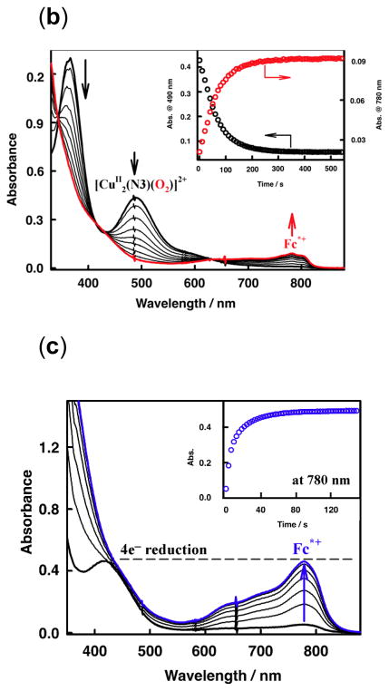
Other complexes shown in Fig. 9 also have been shown to catalyze the O2-reduction to water, even though they form very different copper-dioxygen adduct structures. [CuII2(N3)(H2O)2](ClO4)4, following reduction, reacts rapidly with molecular oxygen to form a side-on bound μ-η2:η2-peroxo dicopper(II) complex [CuII2(N3)(O2)]2+ (Fig. 9, Fig. 11a), as previously demonstrated [81–83]. When a catalytic amount of [CuII2(N3)(H2O)2]2+ is added to and O2-saturated acetone solution with Fc* and trifluoroacetic acid, O2 is reduced to water and four equiv. Fc*+ are formed, even if excess Fc* relative to O2 (i.e., limiting [O2]) and acid are present (also see the inset for Fig. 11b) [80]. Along with the finding by iodometric titration that no hydrogen peroxide is produced, it was concluded that [CuII2(N3)(H2O)2]2+ is an efficient catalyst for the four-electron reduction of O2 by Fc*. The same results were obtained using the weaker reductant, octamethylferrocene (Me8Fc), however no reaction occurred with 1,1′-dimethylferrocene [80].
Fig. 11.
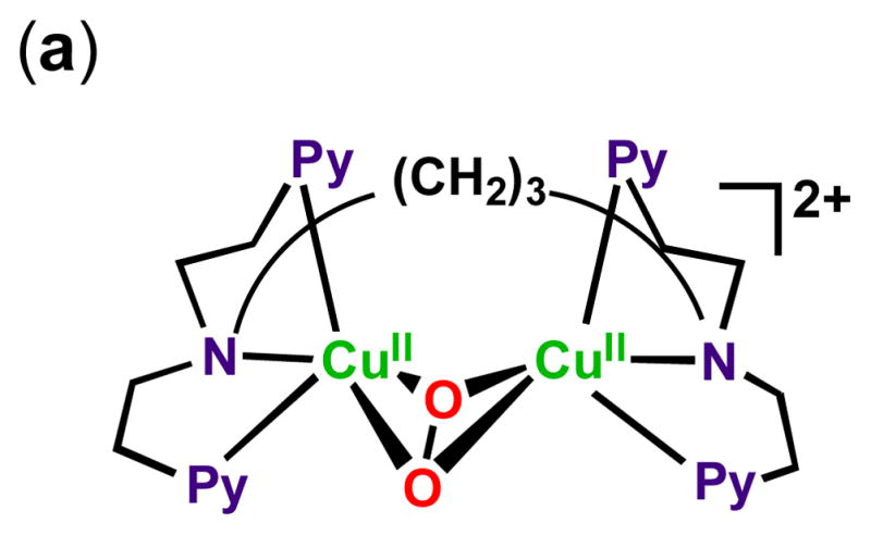
Depiction of the structure of the μ-η2:η2-peroxo dicopper(II) complex [CuII2(N3)(O2)]2+ (b) Formation of the η2:η2-peroxo complex (λmax = 490 nm) in the reaction of [CuI2(N3)]2+ (1.0 × 10⁻⁴ mol L−1) with O2 in the presence of Fc* (8.0 × 10⁻² mol L−1) in acetone at 193 K. The Inset shows the time profiles of the absorbance at 490 nm (black line) and 780 nm (red line) due to [CuII2(N3)(O2)]2+ and Fc*+, respectively. (c) UV/Vis spectral changes observed in the four-electron reduction of O2 (0.22 × 10⁻³ mol L−1) by Fc* (3.0 × 10⁻³ mol L−1) at 298 K and with TFA (1.0 × 10⁻² mol L−1) catalyzed by [CuII2(N3)(H2O)2]2+ (1.0 × 10⁻⁴ mol L−1).
To further break down the individual reaction steps, experiments were carried out on [CuII2(N3)(O2)]2+ (λmax = 365 and 490 nm, Fig. 11c) which was separately generated at 193 K [80]. Electron transfer reduction of this complex by Fc* occurs with concomitant production of two equiv. Fc*+ in acetone, see the decay of absorbances due to [CuII2(N3)(O2)]2+ which are accompanied by the rise of absorbance at 780 nm due to Fc*+ (Fig. 11c Inset). Kinetic interrogation on the rate of electron-transfer led to determination that Fc* reduction of [CuII2(N3)(O2)]2+ occurred with ket = 18 mol−1 L s−1 (193 K), a value that was not altered in the presence of one equiv. acid. Me2Fc was not able to effect this reduction. The latter finding indicates that the electron transfer is not coupled with the protonation of [CuII2(N3)(O2)]2+ [80].
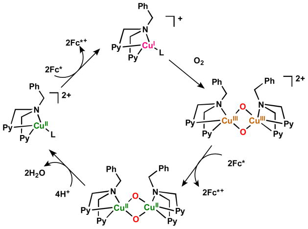
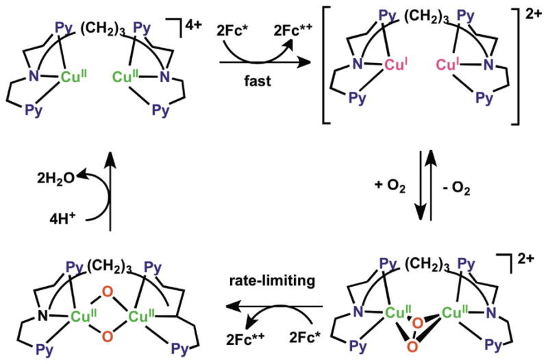
Overall, the data supported a reaction mechanism where the dicopper(II) catalyst was reduced by Fc* to a dicopper(I) complex, previously established to be [CuI2(N3)]2+, which reacts very rapidly with O2, giving [CuII2(N3)(O2)]2+. In a rate-limiting step, this is reduced likely to a transient bis-μ-oxo-dicopper(II) species which is very rapidly protonated to give back the catalyst and two mol-equiv H2O, thus completing the 4e−/4H+ reduction of dioxygen, Scheme 7 [80]. Consistent with the proposed mechanism and a piece of valuable new information derived from the studies was a very good estimate of the potential for reduction of [CuII2(N3)(O2)]2+. Based on the known one-electron oxidation potentials for ferrocene derivatives and that of N,N,N′,N′-tetramethylphenylenediamine (TMPD) (Eox = 0.12 V vs. SCE) [80], which also effected the reduction of [CuII2(N3)(O2)]2+ accompanied by the formation of TMPD•+, the one-electron reduction potential of [CuII2(N3)(O2)]2+ could be estimated to be Ered = 0.19 (± 0.07) V vs. SCE [80]. That value is significantly lower than the Ered value of (0.37 V vs. SCE) for the catalyst [CuII2(N3)(H2O)2]2+, these results being consistent with rapid reduction of the latter followed by rate limiting reduction of the μ-η2:η2-peroxo dicopper(II) complex [CuII2(N3)(O2)]2+ formed during the catalytic cycle [80]. There now exists a huge literature describing how μ-η2:η2-peroxo dicopper(II) complexes [Cu…Cu ~ 0.36 nm; O–O ~ 0.14 – 0.15 nm; νO–O < 760 cm−1, resonance Raman spectroscopy (rR)] not infrequently exist in equilibrium with a bis-μ-oxo-dicopper(III) isomer Cu···Cu ~ 0.28 nm, O···O ~ 0.23 nm, νCu–O ~ 600 cm−1 (intense) [75, 77, 83–85]. While rR measurements on [CuII2(N3)(O2)]2+ do not show any hint of the presence of a species [CuIII2(N3)(O)2)2+ [83], it still had to be considered that it might be formed here in this catalytic process, and that the bis-μ-oxo-dicopper(III) species was actually the species which was being reduced by Fc*, thus following and not prior to O–O cleavage. However, this could be ruled out, as follows. The temperature dependence of the various electron-transfer steps were evaluated, leading to the finding that electron transfer from Fc* or Me8Fc to both [CuII2(N3)(H2O)2]2+ and [CuII2(N3)(O2)] 2+ virtually the same values for ΔS≠ (~ 0, which is expected and typical for outer-sphere electron transfer chemistry) indicating a direct process, not what one would find if a conversion of [CuII2(N3)(O2)]2+ to bis-μ-oxo-dicopper(III) species [CuII2(N3)(O)2]2++ occurred [80].
Scheme 7.
With the value Ered = 0.19 (± 0.07) V vs. SCE determined for peroxo complex [CuII2(N3)(O2)]2+, ΔGet values for Fc* and Me8Fc could be determined, (−0.27 ± 0.07) and (−0.23 ± 0.07) eV, respectively. The λ value for electron transfer from Fc* and Me8Fc to [CuII2(N3)(O2)]2+ could then be estimated [80] and found to be 2.2 (± 0.1) eV, which was significantly larger than the corresponding value for electron transfer from ferrocene derivatives to the dicopper(II) catalyst [CuII2(N3)(H2O)2]2+. This finding is also consistent with direct electron transfer from ferrocene derivatives to the peroxo-dicopper(II) complex intermediate, as large structural changes would of course be a part of an O–O cleavage process, but not so for the case where a bis-μ-oxo-dicopper(III) complex with already cleaved O–O bond were undergoing simple electron-transfer reduction to give the corresponding bis-μ-oxo-dicopper(II) complex [CuII2(N3)(O)2]2+ (that in Scheme 8) [80].
Scheme 8.
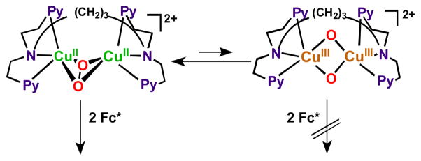
Investigations on O2-reduction catalys is with [CuII(BzPY1)]2+ (Fig. 9) were carried out in a similar manner to those discussed for [CuII2(N3)(H2O)2]2+ (vide supra) [80]. The findings can be summarized as follows (Scheme 9) [80]: [CuII(BzPY1)]2+ is reduced by Fc* giving copper(I) species [CuI(BzPY1)]2+ whose reaction with O2 is known to afford the bis-μ-oxo dicopper(III) complex [{CuIII(BzPY1)}2(O)2]2+ (λmax = 390 nm). Electron transfer reduction by Fc* occurs rapidly upon mixing in acetone even at 193 K to produce two equiv. of Fc*+ and the reaction rate was not affected by TFA. Fast protonation gives two mole-equiv. H2O and the catalyst. Reaction of [{CuII(BzPY1)}2(O)2]2+ also occurs with weaker electron donors, Me2Fc and even Fc itself. In the latter case however, no catalysis occurs because these latter reductants can’t even reduce [CuII(BzPY1)]2+ to [CuI(BzPY1)]+ as ΔGet > 0, and therefore the catalytic cycle cannot begin [80].
Scheme 9.
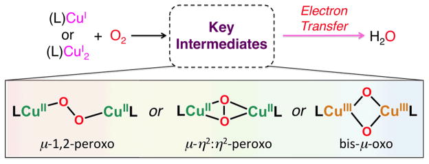
To summarize (Scheme 10), different copper(II) complexes giving rise to completely very different Cu2O2 structures following reduction and reaction with molecular oxygen, all are readily reduced by ferrocene one-electron reductants, leading to the copper ion catalyzed overall 4e−/4H+ reduction of dioxygen to water [80]. The key step leading to this reaction stoichiometry is ferrocenyl reductive O–O bond cleavage (by two-electron equiv.) at the peroxo-dicopper(II) level, at least for two of the three cases. In the other, with catalyst [CuII(BzPY1)]2+, the copper(I)/O2 chemistry already gives rise to O–O cleavage and a bis-μ-oxo-dicopper(III) intermediate which is then reduced (Scheme 10). To finish (or start) the catalytic cycle, the copper(II) complex(es) then formed are reduced to copper(I) for further O2-reaction. With the great variations in ligand design for copper complexes which are possible, and can lead to varying patterns of Cu(II)/Cu(I) or Cu(III)/Cu(I) redox cycles, the possibility of developing systems which may effect the catalytic 2e−/2H+ O2-reduction to hydrogen peroxide seems real.
Scheme 10.
The electrocatalytic four-electron reduction of O2 has also been achieved using electrodes on which Cu complexes are immobilized [86–96]. Whether a mononuclear Cu complex or a dinuclear Cu complex is responsible for the four-electron reduction of O2 was examined by determining the dependence of the rate on the Cu coverage. Anson and coworkers determined that the electrocatalytic rate of the O2-reduction was first-order in Cu coverage, suggestive of a mononuclear Cu site as the active catalyst [86,87]. On the other hand, the rate of O2 reduction with a CuI complex of 3-ethynyl-phenanthroline covalently immobilized onto an azide-modified glassy carbon surface is second-order in the Cu coverage at moderate overpotential, suggesting that two CuI species are necessary for the efficient four-electron four-proton reduction of O2 [95,96]. In this case, a dinuclear peroxo-Cu complex is proposed to be a key intermediate for the four-electron reduction of O2, in a reaction cycle which is similar to that shown in Scheme 6. In the context of the present review, it should be noted that for recent cases of electrocatalytic systems, and depending on conditions of applied potential or pH, increases in the relative amount of two-electron O2-reduction to H2O2 may be observed [96,97].
In the context of the chemical reduction of molecular oxygen and production of hydrogen peroxide which may come about with copper complexes, there is in fact a pertinent literature concerning the (di)copper complex mediated catalytic oxidation of catechols to quinones [98–100]. This research is bioinspired as enzyme catechol oxidases are known to effect this reaction at an active site comprising two adjacent (0.3 – 0.4 nm) copper ions. The stoichiometry of reaction for the enzyme is thought to be:
However, for a number of chemical model system studies aimed at exploring mechanistic details and typically employing 3,5-di-tert-butylcatechol (DTBC) as a convenient substrate; 3,5-di-tert-butyl-1,2-benzoquinone (DTBQ) along with hydrogen peroxide are produced stoichiometrically, according to
Mechanisms proposed by several groups [101–106] involve the interaction of DTBC at a one ligand-copper(II) site, whereupon valence tautomerism to give a Cu(I)-semiquinone species leads to O2-reactivity giving a copper(II)-superoxo species which in a rate limiting step abstracts a substrate hydrogen atom, eliminating DTBQ and hydrogen peroxide while regenerating the catalytic copper(II) containing complex. Another possible mechanism would proceed via acid-base chemistry where a Cu(II)-peroxo-Cu(II) intermediate reacts with a catechol, releasing H2O2 and leaving a bound catecholate dicopper(II) center; the latter would undergo internal redox to give quinone product and a dicopper(I) moiety which reacts with dioxygen to repeat the cycle [99, 104,107]. With such known chemistries, it may well be that investigation of copper complex electrocatalytic or chemically selective reduction to H2O2 should be pursued.
In general, copper complexes, as mentioned here, have seen increasing use and success in O2-reduction electrocatalytic applications [73,94–97,108]. But, also as additives or other enhancements of various types, copper in various forms has been shown to boost O2-reduction electrocatalytic behavior. Some recent examples include (i) a system in which a multicopper oxidase is linked covalently to a multiwall carbon nanotube [109], (ii) a fuel cell which utilizes a Cu-Cu2O redox cycle [110], (iii) ACu(II) grafted TiO2 catalyst, wherein reduced copper(I) formed from a photolytic process facilitates O2-reduction [111], (iv) copper nanoclusters deposited onto a glassy-carbon electrode showed very favorable O2 reductive electrocatalytic activity [112] and (v) a modified platinum electrode, where sub-monolayer quantities of copper were incorporated into Pt(111) resulted in an eight-fold enhancement in O2-reduction electrocatalytic activity [113].
3. H2O2 formation by solar cell
In order to utilize H2O2 as an energy carrier, hydrogen peroxide should be produced by a convenient method without any special equipment. One such method is electroreduction of O2 with a solar cell in an acidic aqueous solution under air [24]. The solar cell is a convenient power source usable anywhere during the sun-shiny days. H2O2 can be produced anywhere by plugging electrodes with an O2 reduction catalyst into solar cells in an acidic solution. H2O2 production by the electrocatalytic reduction of O2 under air with electrical power generated by a photovoltaic solar cell has been performed using Co-porphyrin compounds. This is depicted in Fig. 12 for catalysts in an acidic solution at room temperature [24], because cobalt porphyrins act as efficient selective two-electron reduction of O2 as described in a previous section [31,32].
Fig. 12.

Cobalt porphyrins employed for electrocatalytic reduction of O2 to H2O2 [24].
Fig. 13 shows the O2 reduction current recorded against voltage vs. saturated calomel electrode (SCE) using a glassy carbon electrode modified by the cobalt porphyrins shown in Fig. 12 in an aqueous solution containing hydrosulphuric acid (1 mol L−1) [24]. Dioxygen reduction currents were observed when using [Co(TCPP)], [Co(TPP)] and [Co(OEP)], the details depending on the particular porphyrin structure. The highest on-set potential of 0.3 V was observed with [Co(TCPP)] [24]. The thermodynamic potential for the two-electron reduction of O2 at a given pH is 0.65 V, thus, the overpotential for O2 reduction was 0.35 V for [Co(TCPP)]. The onset potential observed on [Co(TPP)] was around 0.25 V comparable to that of [Co(TCPP)]. The onset potential of [Co(OEP)] was 0.1 V, thus indicating a larger overpotential is required for O2 reduction.
Fig. 13.
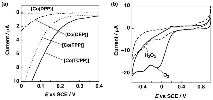
(a) Electrocatalytic current at oxygen reduction. ([Co(DPP)] – –, [Co(OEP)] – · –, [Co(TPP)] - - -, [Co(TCPP)] —). (b) CV of [Co(TCPP)] at scan rate = 20 mV s−1 (with 3 × 10⁻³ mol L−1 H2O2 – –, with oxygen bubbling: ——). The measurements were performed in 1.0 × 10⁻¹ mol L−1 hydrosulphuric acid at 298 K. To prevent contamination of the coordinating ion or ligands, ultrapure water was used in the experiments.
A cyclic voltammogram of [Co(TCPP)] in the presence of oxygen gas and H2O2 (3 × 10⁻³ mol L−1) (Fig. 13b) exhibits a reduction peak which appears around 0 V in the presence of O2, corresponding to two-electron reduction of O2 to produce H2O2 [24]. The selective production of H2O2 can be achieved with the [Co(TCPP)] catalyst when the applied potential is controlled to around 0 V. The current efficiency for H2O2 production was nearly 100% in 1.0 × 10⁻¹ mol L−1 hydrosulphuric acid [24].
H2O2 production by the reduction of O2 in an acidic aqueous solution was also performed using a conventional Si photovoltaic solar cell, which behaves as an electric power source, with an output of 0.5 V at 2.5 mA [24]. A glassy carbon electrode (~1 cm2) mounted with a Co-porphyrin and Pt wire electrode were connected to the negative and positive electrodes. After 11 hours running in a 1.0 × 10⁻¹ mol L−1 hydrosulphuric acid (~7 mL), solution, the amount of H2O2 produced reached 1.46 × 10⁻⁵ mol with [Co(TCPP)] [24]. Thus, H2O2 was conveniently produced by the electrocatalytic reduction of O2 with a conventional photovoltaic solar cell although the catalytic behavior as well as cell and electrode structures will require improvement for practical application.
4. Direct H2O2 fuel cells
Fuel cells require oxygen as the oxidant and therefore the use in air-free environments such as outer space and underwater require a compressed oxygen tank. Hydrogen peroxide (H2O2) has been utilized as an alternative liquid oxidant in place of gaseous O2. A number of fuel cells with H2O2 as the oxidant have been developed using borohydride [114–116], metals [117–119], methanol [120,121], hydrazine [122] and biofuels [123] as reductants. H2O2 can also be used as a reductant and direct H2O2 cells have recently been developed [124–127]. Direct H2O2 fuel cells have number of merits as compared with other fuel cells: (1) H2O2 is liquid and soluble in water and thereby easy to store and carry: (2) H2O2 has higher standard reduction potential than O2 (e.g., 1.776 V vs. SHE for H2O2 and 1.229 V vs. SHE for O2 in acidic medium [124]; (3) there is no need to use membranes, because H2O2 can act both oxidant and reductant. Thus, fuel cells with H2O2 used as both oxidant and reductant can have much simpler cell structure (i.e., one compartment cell without membrane), theoretically providing higher power output than those with oxygen used as an oxidant [124]. The reactions occurring at anode and cathode of the H2O2 fuel cell are given by Eqs. (8) – (10) [24,125–127].
| (8) |
| (9) |
| (10) |
Thus, H2O2 fuel cells emit only oxygen after electrical power generation. The theoretical maximum of the output potential of the H2O2 fuel cell is 1.09 V [125–127], which is comparable to those of a hydrogen fuel cells (1.23 V) and a direct methanol fuel cell (1.21 V) [127]. A one compartment H2O2 fuel cell has been constructed by using an Au plate as an anode and an Ag plate as a cathode, because these metal plates act as selective oxidation and reduction catalyst toward H2O2, respectively [126]. Such a one-compartment structure without membrane is certainly more promising for development of low-cost fuel cells as compared with two compartment fuel cells with membranes. However, the voltage achieved from the fuel cell described above was 0.12 V, which is lower than the theoretically achievable voltage of 1.09 V; this was due to a large over-potential at the Ag cathode [125].
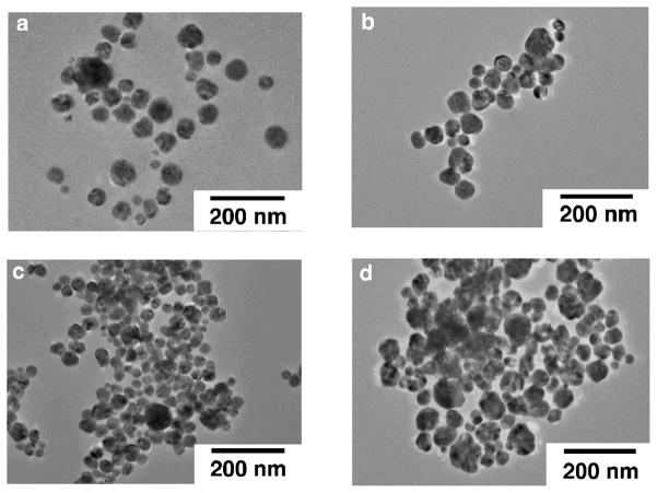
Increasing the specific surface area is one of the easiest means to achieve high catalytic activity per weight. In order to increase the surface area of Ag plate, nanoparticles of Ag with high specific surface area were examined as a cathode of the one-compartment H2O2 fuel cell [24]. Also addition of foreign elements of Pb to modify the electronic structure of Ag nanoparticles was examined [24]. Fig. 14 shows the TEM images of Ag and Ag-Pb alloy nanoparticles used for the construction of one-compartment H2O2 fuel cells. The average Ag nanoparticles diameter was 41 nm.
Fig. 14.
TEM images of Ag or Ag-Pb alloy nanoparticles. (a) Ag nanoparticles, (b) Ag-Pb alloy (Ag:Pb = 9:1), (c) Ag-Pb alloy (7:3) and (d) Ag-Pb alloy (Ag:Pb = 6:4).
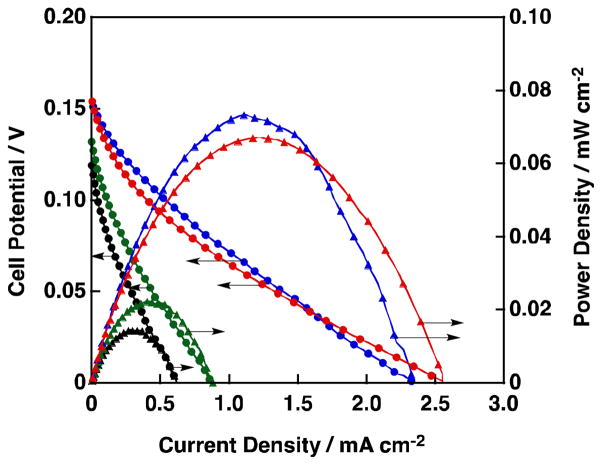
The Ag based nanoparticles were mounted on a glassy carbon electrode by a drop-casting method [24] and the one-compartment H2O2 fuel cells constructed were operated under basic conditions using an aqueous solution containing NaOH (1.0 mol L−1) and H2O2 (3.0 × 10⁻¹ mol L−1). Fig. 15 shows I-V and I-P curves for such H2O2 fuel cells where the current density was normalized by the geometric surface area of the glassy carbon electrode [24]. The results obtained with Ag nanoparticles without Pb addition are plotted in black color in Fig. 15. The performance of the H2O2 fuel cell using Ag nanoparticles was comparable to that using Ag plate. On the other hand, when Ag-Pb alloys were used as cathodes [Ag:Pb = 9:1 (blue), 7:3 (red), 6:4 (green) in Fig. 15], cell performance was improved, i.e., higher power densities, open circuit voltages and short-circuit currents were obtained compared to those using the Ag nanoparticles as the cathode. Large values were achieved on Ag-Pb alloys with the ratios of 9:1 and 7:3 although the open-circuit potential of ca. 150 mV was still far from the theoretical potential (1.09 V) [24].
Fig. 15.
I-V and I-P curves of a one-compartment H2O2 fuel cell with Ag or Ag-Pb alloy cathode. (Au anode. 1.0 mol L−1 NaOH, 3.0 × 10⁻¹ mol L−1 H2O2. black: Ag, green: Ag:Pb = 6:4, red: Ag:Pb = 7:3 and blue: Ag:Pb = 9:1).
In order to achieve a more efficient system, the medium conditions should be the same or similar for H2O2 production and power generation. Hydrogen peroxide fuel cells using an Ag-based cathode can generate power only in basic media, however, H2O2 production by O2 reduction was performed under acidic conditions [24]. H2O2 is not stable under basic conditions, thus, there is a tremendous need to develop an H2O2 fuel cell which can be operated under acidic conditions for the ideal combination with the production of H2O2 via the two-electron reduction of O2 with a solar cell.
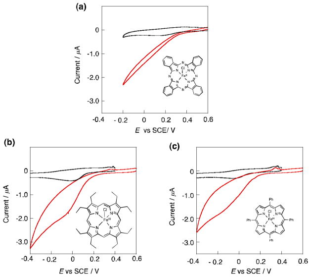
A one-compartment H2O2 fuel cell using an iron phthalocyaninato complex can be operated under acidic conditions [126]. The choice of iron porphyrin and analogous compounds for H2O2 reduction is quite reasonable because in natural systems, the reduction of hydrogen peroxide is owing to hydroperoxidases, which contain iron(III)-porphyrins in their active sites [128–130]. The activity of iron complexes depicted in Fig. 16 was examined for H2O2 reduction [126]. Fig. 17 shows the cyclic voltammograms (CV) of H2O2 with an iron complex mounted glassy carbon as a working electrode in an aqueous solution of acetate buffer (pH 4) containing 3.0 × 10⁻¹ mol L−1 H2O2 [126]. The black curves in Fig. 17 are CVs of each iron complex in an acetate buffer solution without H2O2. A catalytic current of the H2O2 reduction was observed in a cathodic sweep with all the Fe complexes, indicating they act as catalysts for the H2O2 reduction in acidic media. The onset potentials for H2O2 reduction on electrodes with [FeIII(OEP)Cl], [FeIII(TPP)Cl] and [FeIII(Pc)Cl] were ca. 0.2 V, 0.2 V and 0.5 V (vs. SCE), respectively. Thus, [FeIII(Pc)Cl] showed the smallest overpotential in this acidic solution, in comparison to the FeIII porphyrin complexes.
Fig. 16.

Chemical structures of porphyrin and phthalocyanine iron(III) complexes similar to active site structures of hydroperoxidases as candidates of cathodes for an H2O2 fuel cell. (a) [FeIII(Pc)Cl], (b) [FeIII(OEP)Cl] and (c) [FeIII(TPP)Cl].
Fig. 17.
Cyclic voltammograms of H2O2 on glassy carbon electrodes modified with FeIII complexes. (a) [FeIII(Pc)Cl], (b) [FeIII(OEP)Cl] and (c) [FeIII(TPP)Cl]. The measurements were performed in an acetate buffer solution (pH 4) containing 3.0 × 10⁻³ mol L−1.
A one-compartment H2O2 fuel cell working in an acidic media was constructed with a glassy carbon electrode mounting [FeIII(Pc)Cl] as a cathode and Ni metal as an anode [126]. The cell performance was evaluated by dipping the anode and cathode in a buffer solution containing 3.0 × 10⁻¹ mol L−1 H2O2. Fig. 18 shows the cell performances of the H2O2 fuel cells in acidic solutions containing 3.0 × 10⁻¹ mol L−1 H2O2 at 293 K [126]. Fig. 18a displays the I–P and I–V curves obtained by the operation of the fuel cell under the conditions of pH 4 (black) and pH 5 (blue). In both cases, the open circuit potentials were ca. 0.24 V, which is significantly higher than that (0.15 V) of the H2O2 fuel cell using a Ag cathode working under basic conditions [24,125]. The maximum power density was improved from 0.39 μWcm−2 at pH 5 to 0.44 μWcm−2 at pH 4 by decreasing the pH. The I–V and I–P curves obtained for the H2O2 fuel cell operated at pH 3 were much higher in both open circuit potential and power density as displayed in Fig. 18b. The power density reached to 10 μWcm−2, which is more than 20 times higher than that obtained under pH 4 and pH 5 conditions. The open-circuit potential of 0.5 V is more than three times higher than that (0.15 V) of the one-compartment H2O2 fuel cell operated under basic conditions [24,125]. A further decrease in pH resulted in the decomposition of H2O2 on the surface of the Ni anode. Thus, the conditions of pH 3 are the optimum for operating the H2O2 fuel cell using [FeIII(Pc)Cl] as the cathode.
Fig. 18.
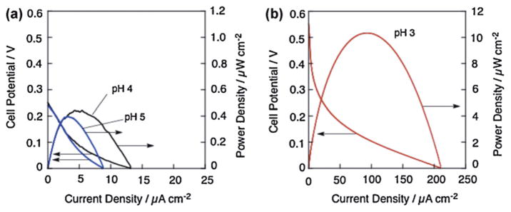
I–V and I–P curves of a one-compartment H2O2 fuel cell with Ni anode and [FeIII(Pc)Cl] cathode. Performance tests were conducted in an acetate buffer containing 3.0 × 10⁻¹ mol L−1 H2O2. The pH of the solutions was fixed to 5 (a, blue), 4 (a, black) or 3 (b, red). Currents and powers were normalized by a geometric surface area of electrode.
The chemical structure of [FeIII(Pc)Cl] under acidic condition was investigated by an acid titration of [FeIII(Pc)Cl] with trifluoroacetic acid (TFA) using UV-vis spectroscopy as shown in Fig. 19 [126]. To the benzonitrile solution of [FeIII(Pc)Cl] (4.0 × 10⁻⁵ mol L−1), a known amount of TFA (2 – 16 × 10−3 mol L−1) was added and UV-vis spectral changes monitored. By the acid addition TFA, an intense absorption band around 656 nm assigned to [FeIII(Pc)Cl] became weaker and new absorption bands appeared around 520 and 720 nm (Fig. 19a), which were assigned to the protonated iron phthalocyanate complex [131]. The slope of Hill plot by using absorption change at 520 nm shown in Fig. 19b was 1.2, indicating that one proton is associated with in the change of UV-vis absorbance. The change was owing to the protonation of one of imine group of the phthalocyanine ligand. The protonation constant K was determined from the titration in Fig. 19 to be 160 mol−1 L [126]. The protonation to the phthalocyanine ligand provided a positive shift of a redox potential of Fe(II)/Fe(III) and stabilization of the reduced state of Fe(II) then suitable for H2O2 reduction.
Fig. 19.
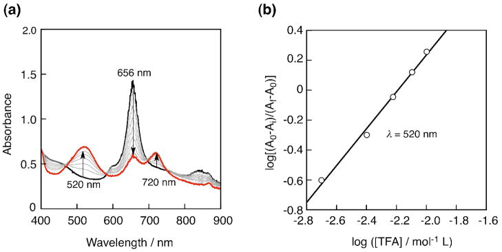
(a) UV-vis absorption change of a benzonitrile solution of [FeIII(Pc)Cl] (4.0 × 10⁻⁵ mol L−1) by adding trifluoroacetic acid (2 – 16 × 10−3 mol L−1). (b) The Hill plot obtained from monitoring of the absorption changes at 520 nm.
The protonation of [FeIII(Pc)Cl] improves the catalytic activity of [FeIII(Pc)Cl] for H2O2 reduction, however, the cationic nature of [FeIII(PcH)Cl]+ decreases the stability because its solubility in water increases [126]. As a result, a serious deterioration in the cell performance was observed during the course of repetitive tests. Fig. 20 (black) shows the resulting potential decrease of the power density of 20 μA cm−2 (not open circuit potential) by the repetitive tests [126]. A high potential of 0.28 V observed in the first test decreased to ca. 0.1 V after repetition. The robustness of [FeIII(PcH)Cl]+ was improved by coating of the complex with a protic membrane, Nafion®, which is a highly acidic polymer containing sulfonate groups at the end of side chains [126]. A glassy carbon electrode was coated with Nafion® after mounting [FeIII(Pc)Cl], and an H2O2 fuel cell was constructed with the electrode. Subsequent repetitive tests on this H2O2 fuel cell were performed at pH 3. As indicated in Fig. 20 (red), the potential of more than 0.25 V observed in the first cycle was maintained in the repetitive tests [126]. Thus, the coating with Nafion® effectively improved the stability of the cell performance.
Fig. 20.
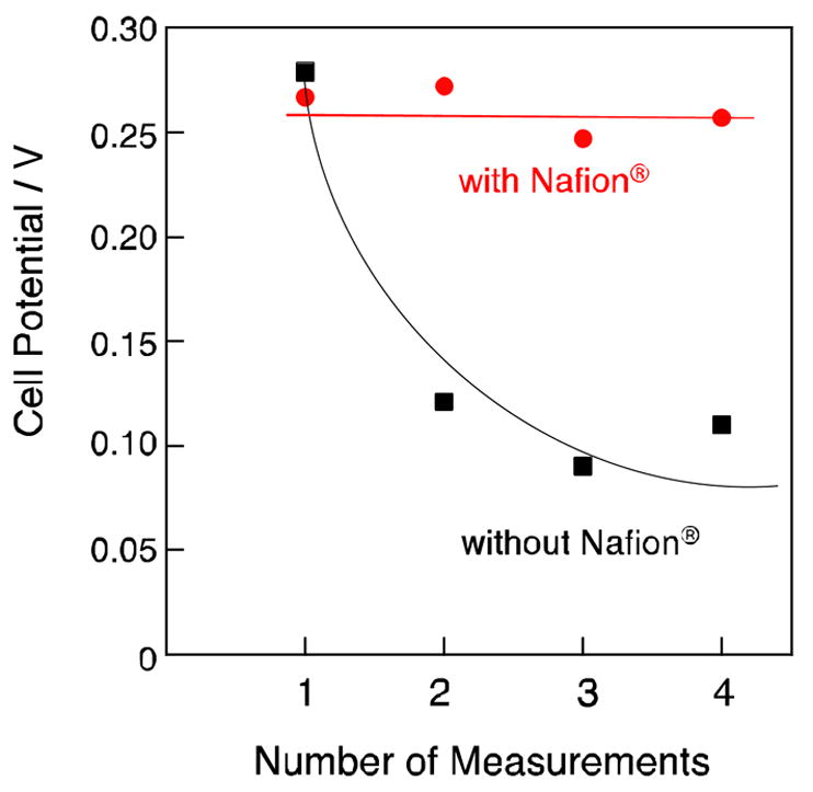
Potential changes by repetitive measurements of H2O2 fuel cells with the Nafion® coated [FeIII(Pc)Cl] cathode (red) and without Nafion® coating (black). Potentials required to achieve the power density of 20 μA cm−2 were recorded.
5. Conclusions
In this review, it has been shown that a variety of metal complexes can catalyze reduction of O2 by one-electron reductants in the presence of an acid in homogeneous solution. Electrocatalytic reduction of O2 can also be achieved using electrodes modified with metal complexes. The number of electrons transferred during O2 reduction is two or four depending of type of metals and ligands. In the case of biscobalt porphyrins and biscobalt porphyrin-corrole complexes, the Co-Co distance is crucial to attain the four-electron reduction of O2, because the formation of the dinuclear Co(III) μ2-η1:η1-peroxo complex with suitable Co-Co distance and the cleavage of the O-O bond are required for the four-electron reduction of O2. In the case of cytochrome c oxidase model compounds, however, a Fe porphyrin without a Cu unit can catalyze the four-electron reduction of O2. In this case, an Fe(III)-hydroperoxo complex can be further reduced by one-electron reductants in the presence of an acid to produce water. Electrocatalytic four-electron reduction of O2 can also be attained using electrodes modified with cytochrome c oxidase model complexes. Cu complexes alone can also catalyze the four-electron reduction of O2 by one-electron reductants in the presence of an acid in homogeneous and heterogeneous systems. Hydrogen peroxide produced by electrocatalytic reduction of O2 using electrodes modified with metal complexes acting as catalysts for selective two-electron reduction of O2 can be used as a fuel in a hydrogen peroxide fuel cell. A hydrogen peroxide fuel cell has great advantages in comparison with other fuel cells which require O2 as the oxidant, because it can be operated using a one-compartment cell without a membrane and in air-free environments such as in outer space and underwater. Future scrutiny is desired to improve the catalytic activity for the selective two-electron reduction of O2 to H2O2, the latter being promising candidates as renewable and clean energy sources.
Acknowledgments
The authors gratefully acknowledge the contributions of their collaborators and coworkers mentioned in the cited references, and support by a Grant-in-Aid (Nos. 20108010 and 237500141), a Global COE program, ‘the Global Education and Research Center for Bio-Environmental Chemistry’ from the Ministry of Education, Culture, Sports, Science and Technology, Japan and KOSEF/MEST through WCU project (R31-2008-000-10010-0), Korea. K.D.K. also thanks the USA National Institutes of Health for support.
References
- 1.Seinfeld JH. AIChE J. 2011;57:3259. [Google Scholar]
- 2.Royer DL, Berner RA, Park J. Nature. 2007;446:530. doi: 10.1038/nature05699. [DOI] [PubMed] [Google Scholar]
- 3.Lewis NS, Nocera DG. Proc Natl Acad Sci USA. 2006;103:15729. doi: 10.1073/pnas.0603395103. [DOI] [PMC free article] [PubMed] [Google Scholar]
- 4.Nocera DG. Chem Soc Rev. 2009;38:13. doi: 10.1039/b820660k. [DOI] [PubMed] [Google Scholar]
- 5.Gray HB. Nat Chem. 2009;1:7. doi: 10.1038/nchem.141. [DOI] [PubMed] [Google Scholar]
- 6.Jiao F, Frei H. Energy Environ Sci. 2010;3:1018. [Google Scholar]
- 7.Balzani V, Credi A, Venturi M. ChemSusChem. 2008;1:26. doi: 10.1002/cssc.200700087. [DOI] [PubMed] [Google Scholar]
- 8.Fukuzumi S. Eur J Inorg Chem. 2008:1351. [Google Scholar]
- 9.Dau H, Zaharieva I. Acc Chem Res. 2009;42:1861. doi: 10.1021/ar900225y. [DOI] [PubMed] [Google Scholar]
- 10.Gust D, Moore TA, Moore AL. Acc Chem Res. 2009;42:1890. doi: 10.1021/ar900209b. [DOI] [PubMed] [Google Scholar]
- 11.Fukuzumi S, Yamada Y, Suenobu T, Ohkubo K, Kotani H. Energy Environ Sci. 2011;4:2754. [Google Scholar]
- 12.Momirlan M, Veziroglub TN. Int J Hydrogen Energy. 2005;30:795. [Google Scholar]
- 13.Dunn S. Encyclopedia of Energy. Vol. 3. Elsevier Inc; 2004. p. 241. [Google Scholar]
- 14.Fukuzumi S, Kobayashi T, Suenobu T. ChemSusChem. 2008;1:827. doi: 10.1002/cssc.200800147. [DOI] [PubMed] [Google Scholar]
- 15.Baldi A, Dam B. J Mater Chem. 2011;21:4021. [Google Scholar]
- 16.Schlapbach L, Züttel A. Nature. 2001;414:353. doi: 10.1038/35104634. [DOI] [PubMed] [Google Scholar]
- 17.Rowsell JLC, Yaghi OM. Angew Chem Int Ed. 2005;44:4670. doi: 10.1002/anie.200462786. [DOI] [PubMed] [Google Scholar]
- 18.Bluhm ME, Bradley MG, Butterick R, III, Kusari U, Sneddon LG. J Am Chem Soc. 2006;128:7748. doi: 10.1021/ja062085v. [DOI] [PubMed] [Google Scholar]
- 19.Orinakova R, Orinak A. Fuel. 2011;90:3123. [Google Scholar]
- 20.Yamanaka I, Murayama T. Angew Chem Int Ed. 2008;47:1900. doi: 10.1002/anie.200704431. [DOI] [PubMed] [Google Scholar]
- 21.Disselkamp RS. Int J Hydrogen Energy. 2010;35:1049. [Google Scholar]
- 22.Disselkamp RS. Energy Fuels. 2008;22:277. [Google Scholar]
- 23.Sanli AE, Aytac A. Int J Hydrogen Energy. 2011;36:869. [Google Scholar]
- 24.Yamada Y, Fukunishi Y, Yamazaki S, Fukuzumi S. Chem Commun. 2010;46:7334. doi: 10.1039/c0cc01797c. [DOI] [PubMed] [Google Scholar]
- 25.Nishimi T, Kamachi T, Kato K, Kato T, Yoshizawa K. Eur J Org Chem. 2011:4113. [Google Scholar]
- 26.Fukuzumi S, Ishikawa K, Tanaka T. Chem Lett. 1986:1. [Google Scholar]
- 27.Fukuzumi S, Chiba M, Ishikawa M, Ishikawa K, Tanaka T. J Chem Soc, Perkin Trans. 1989;2:1417. [Google Scholar]
- 28.Sawyer DT, Calderwood TS, Yamaguchi K, Angelis CT. Inorg Chem. 1983;22:2577. [Google Scholar]
- 29.Sargeson AM, Lay PA. Aust J Chem. 2009;62:1280. [Google Scholar]
- 30.Creaser II, Geue RJ, Mac J, Harrowfield B, Herlt AJ, Sargeson AM, Snow MR, Springborg J. J Am Chem Soc. 1982;104:6016. [Google Scholar]
- 31.Fukuzumi S, Mochizuki S, Tanaka T. Inorg Chem. 1989;28:2459. [Google Scholar]
- 32.Fukuzumi S, Okamoto K, Gros CP, Guilard R. J Am Chem Soc. 2004;126:10441. doi: 10.1021/ja048403c. [DOI] [PubMed] [Google Scholar]
- 33.Marcus RA. Ann Rev Phys Chem. 1964;15:155. [Google Scholar]
- 34.Yang ES, Chan M-S, Wahl AC. J Phys Chem. 1988;84:3094. [Google Scholar]
- 35.Rohrbach DF, Deutsch E, Heineman WR, Pasternack RF. Inorg Chem. 1977;16:2650. [Google Scholar]
- 36.Pasternack RF, Spiro EG. J Am Chem Soc. 1978;100:968. [Google Scholar]
- 37.Langley R, Hambright P. Inorg Chem. 1985;24:1267. [Google Scholar]
- 38.Collman JP, Hutchison JE, Lopez MA, Tabard A, Guilard R, Seok WK, Ibers JA, L’Her M. J Am Chem Soc. 1992;114:9869. [Google Scholar]
- 39.Bolze F, Gros CP, Drouin M, Espinosa E, Harvey PD, Guilard R. J Organomet Chem. 2002;643–644:89. [Google Scholar]
- 40.Chang CJ, Deng Y, Shi C, Chang CK, Anson FC, Nocera DG. Chem Commun. 2000:1355. [Google Scholar]
- 41.Chang CJ, Baker EA, Pistorio BJ, Deng Y, Loh Z-H, Miller SE, Carpenter SD, Nocera DG. Inorg Chem. 2002;41:3102. doi: 10.1021/ic0111029. [DOI] [PubMed] [Google Scholar]
- 42.Schmidt S, Heinemann FW, Grohmann A. Eur J Inorg Chem. 2000:1657. [Google Scholar]
- 43.Dai X, Kapoor P, Warren TH. J Am Chem Soc. 2004;126:4798. doi: 10.1021/ja036308i. [DOI] [PubMed] [Google Scholar]
- 44.Hikichi S, Yoshizawa M, Sasakura Y, Komatsuzaki H, Moro-oka Y, Akita M. Chem Eur J. 2001;7:5011. doi: 10.1002/1521-3765(20011203)7:23<5011::aid-chem5011>3.0.co;2-c. [DOI] [PubMed] [Google Scholar]
- 45.Gavrilova AL, Qin CJ, Sommer RD, Rheingold AL, Bosnich B. J Am Chem Soc. 2002;124:1714. doi: 10.1021/ja012386z. [DOI] [PubMed] [Google Scholar]
- 46.Chang CJ, Loh Z-H, Shi C, Anson FC, Nocera DG. J Am Chem Soc. 2004;126:10013. doi: 10.1021/ja049115j. [DOI] [PubMed] [Google Scholar]
- 47.Kadish KM, Frémond L, Shen J, Chen P, Ohkubo K, Fukuzumi S, Ojaimi ME, Gros CP, Barbe J-M, Guilard R. Inorg Chem. 2009;48:2571. doi: 10.1021/ic802092n. [DOI] [PubMed] [Google Scholar]
- 48.Bard AJ, Faulkner LR. Electrochemical Methods: Fundamentals and Applications. 2. John Wiley & Sons, Inc; New York: 2001. [Google Scholar]
- 49.Levich VG. Physicochemical Hydrodynamics. Prentice-Hall, Inc; Englewood Cliffs, N. J: 1962. [Google Scholar]
- 50.Koutecky J, Levich VG. Zh Fiz Khim. 1958;32:1565. [Google Scholar]
- 51.Oyama N, Anson FC. Anal Chem. 1980;52:1192. [Google Scholar]
- 52.Kadish KM, Shen J, Frémond L, Chen P, Ojaimi ME, Chkounda M, Gros CP, Barbe J-M, Ohkubo K, Fukuzumi S, Guilard R. Inorg Chem. 2008;47:6726. doi: 10.1021/ic800458s. [DOI] [PubMed] [Google Scholar]
- 53.Kadish KM, Frémond L, Ou Z, Shao J, Shi C, Anson FC, Burdet F, Gros CP, Barbe J-M, Guilard R. J Am Chem Soc. 2005;127:5625. doi: 10.1021/ja0501060. [DOI] [PubMed] [Google Scholar]
- 54.Ferguson-Miller S, Babcock GT. Chem Rev. 1996;96:2889. doi: 10.1021/cr950051s. [DOI] [PubMed] [Google Scholar]
- 55.Pereira MM, Santana M, Teixeira M. Biochim Biophys Acta. 2001;1505:185. doi: 10.1016/s0005-2728(01)00169-4. [DOI] [PubMed] [Google Scholar]
- 56.Kim E, Chufán EE, Kamaraj K, Karlin KD. Chem Rev. 2004;104:1077. doi: 10.1021/cr0206162. [DOI] [PubMed] [Google Scholar]
- 57.Chufán EE, Puiu SC, Karlin KD. Acc Chem Res. 2007;40:563. doi: 10.1021/ar700031t. [DOI] [PubMed] [Google Scholar]
- 58.Chishiro T, Shimazaki Y, Tani F, Tachi Y, Naruta Y, Karasawa S, Hayami S, Maeda Y. Angew Chem Int Ed. 2003;42:2788. doi: 10.1002/anie.200351415. [DOI] [PubMed] [Google Scholar]
- 59.Collman JP, Boulatov R, Sunderlan CJ, Fu L. Chem Rev. 2004;104:561. doi: 10.1021/cr0206059. [DOI] [PubMed] [Google Scholar]
- 60.Collman JP, Boulatov R, Sunderland CJ. In: The Porphyrin Handbook. Kadish M, Smith KM, Guilard R, editors. Vol. 11. Academic Press; San Diego, CA: 2003. p. 1. [Google Scholar]
- 61.Collman JP, Ghosh S, Dey A, Decreau RA, Yang Y. J Am Chem Soc. 2009;131:5034. doi: 10.1021/ja9001579. [DOI] [PMC free article] [PubMed] [Google Scholar]
- 62.Anson FC, Shi A, Steiger B. Acc Chem Res. 1997;30:437. [Google Scholar]
- 63.Kjaergaard CH, Rossmeisl J, Nørskov JK. Inorg Chem. 2010;49:3567. doi: 10.1021/ic900798q. [DOI] [PubMed] [Google Scholar]
- 64.Halime Z, Kotani H, Fukuzumi S, Karlin KD. Proc Natl Acad Sci USA. 2011;108:13990. doi: 10.1073/pnas.1104698108. [DOI] [PMC free article] [PubMed] [Google Scholar]
- 65.Ghiladi RA, Huang HW, Moënne-Loccoz P, Stasser J, Blackburn NJ, Woods AS, Cotter RJ, Incarvito CD, Rheingold AL, Karlin KD. J Biol Inorg Chem. 2005;10:63. doi: 10.1007/s00775-004-0609-1. [DOI] [PubMed] [Google Scholar]
- 66.Shin H, Lee D-H, Kang C, Karlin KD. Electrochim Acta. 2003;48:4077. [Google Scholar]
- 67.Messerschmidt A. Adv Inorg Chem. 1993;40:121. [Google Scholar]
- 68.Djoko KY, Chong LX, Wedd AG, Xiao Z. J Am Chem Soc. 2010;132:2005. doi: 10.1021/ja9091903. [DOI] [PubMed] [Google Scholar]
- 69.Kosman D. J Biol Inorg Chem. 2010;15:15. doi: 10.1007/s00775-009-0590-9. [DOI] [PubMed] [Google Scholar]
- 70.Solomon EI, Ginsbach JW, Heppner DE, Kieber-Emmons MT, Kjaergaard CH, Smeets PJ, Tian L, Woertink JS. Faraday Discuss. 2011;148:11. doi: 10.1039/c005500j. [DOI] [PMC free article] [PubMed] [Google Scholar]
- 71.Cracknell JA, Vincent KA, Armstrong FA. Chem Rev. 2008;108:2439. doi: 10.1021/cr0680639. [DOI] [PubMed] [Google Scholar]
- 72.Solomon EI, Sundaram UM, Machonkin TE. Chem Rev. 1996;96:2563. doi: 10.1021/cr950046o. [DOI] [PubMed] [Google Scholar]
- 73.Gewirth AA, Thorum MS. Inorg Chem. 2010;49:3557. doi: 10.1021/ic9022486. [DOI] [PubMed] [Google Scholar]
- 74.Fujieda N, Yakiyama A, Itoh S. Dalton Trans. 2010;39:3083. doi: 10.1039/c000760a. [DOI] [PubMed] [Google Scholar]
- 75.Mirica LM, Ottenwaelder X, Stack TDP. Chem Rev. 2004;104:1013. doi: 10.1021/cr020632z. [DOI] [PubMed] [Google Scholar]
- 76.Lewis EA, Tolman WB. Chem Rev. 2004;104:1047. doi: 10.1021/cr020633r. [DOI] [PubMed] [Google Scholar]
- 77.Hatcher LQ, Karlin KD. J Biol Inorg Chem. 2004;9:669. doi: 10.1007/s00775-004-0578-4. [DOI] [PubMed] [Google Scholar]
- 78.Hatcher LQ, Karlin KD. Adv Inorg Chem. 2006;58:131. [Google Scholar]
- 79.Fukuzumi S, Kotani H, Lucas HR, Doi K, Suenobu T, Peterson RL, Karlin KD. J Am Chem Soc. 2010;132:6874. doi: 10.1021/ja100538x. [DOI] [PMC free article] [PubMed] [Google Scholar]
- 80.Tahsini L, Kotani H, Lee Y-M, Cho J, Nam W, Karlin KD, Fukuzumi S. Chem-Eur J. doi: 10.1002/chem.201103215. accepted for publication. [DOI] [Google Scholar]
- 81.Karlin KD, Haka MS, Cruse RW, Gultneh Y. J Am Chem Soc. 1985;107:5828. [Google Scholar]
- 82.Karlin KD, Tyeklár Z, Farooq A, Haka MS, Ghosh P, Cruse RW, Gultneh Y, Hayes JC, Toscano PJ, Zubieta J. Inorg Chem. 1992;31:1436. [Google Scholar]
- 83.Pidcock E, Obias HV, Abe M, Liang H-C, Karlin KD, Solomon EI. J Am Chem Soc. 1999;121:1299. [Google Scholar]
- 84.Henson MJ, Mukherjee P, Root DE, Stack TDP, Solomon EI. J Am Chem Soc. 1999;121:10332. [Google Scholar]
- 85.Que L, Jr, Tolman WB. Angew Chem Int Ed. 2002;41:1114. doi: 10.1002/1521-3773(20020402)41:7<1114::aid-anie1114>3.0.co;2-6. [DOI] [PubMed] [Google Scholar]
- 86.Zhang J, Anson FC. Electrochim Acta. 1993;38:2423. [Google Scholar]
- 87.Lei Y, Anson FC. Inorg Chem. 1994;33:5003. [Google Scholar]
- 88.Marques ALB, Zhang J, Lever ABP, Pietro WJ. J Electroanal Chem. 1995;392:43. [Google Scholar]
- 89.Losada J, del Peso I, Beyer L. Inorg Chim Acta. 2001;321:107. [Google Scholar]
- 90.Dias VLN, Fernandes EN, da Silva LMS, Marques EP, Zhang J, Marques ALB. J Power Sources. 2005;142:10. [Google Scholar]
- 91.Weng YC, Fan F-R, Bard AJ. J Am Chem Soc. 2005;127:17576. doi: 10.1021/ja054812c. [DOI] [PubMed] [Google Scholar]
- 92.Wang M, Xu X, Gao J, Jia N, Cheng Y. Russ J Electrochem. 2006;42:878. [Google Scholar]
- 93.Pichon C, Mialane P, Dolbecq A, Marrot J, Riviere E, Keita B, Nadjo L, Secheresse F. Inorg Chem. 2007;46:5292. doi: 10.1021/ic070313w. [DOI] [PubMed] [Google Scholar]
- 94.Thorum MS, Yadav J, Gewirth AA. Angew Chem Int Ed. 2009;48:165. doi: 10.1002/anie.200803554. [DOI] [PubMed] [Google Scholar]
- 95.McCrory CCL, Ottenwaelder X, Stack TDP, Chidsey CED. J Phys Chem A. 2007;111:12641. doi: 10.1021/jp076106z. [DOI] [PubMed] [Google Scholar]
- 96.McCrory CCL, Devadoss A, Ottenwaelder X, Lowe RD, Stack TDP, Chidsey CED. J Am Chem Soc. 2011;133:3696. doi: 10.1021/ja106338h. [DOI] [PMC free article] [PubMed] [Google Scholar]
- 97.Thorseth MA, Letko CS, Rauchfuss TB, Gewirth AA. Inorg Chem. 2011;50:6158. doi: 10.1021/ic200386d. [DOI] [PubMed] [Google Scholar]
- 98.Selmeczi K, Reglier M, Giorgi M, Speier G. Coord Chem Rev. 2003;245:191–201. [Google Scholar]
- 99.Koval IA, Gamez P, Belle C, Selmeczi K, Reedijk J. Chem Soc Rev. 2006;35:814–840. doi: 10.1039/b516250p. [DOI] [PubMed] [Google Scholar]
- 100.Koval IA, Selmeczi K, Belle C, Philouze C, Saint-Aman E, Gautier-Luneau I, Schuitema AM, van Vliet M, Gamez P, Roubeau O, Lüken M, Krebs B, Lutz M, Spek AL, Pierre J-L, Reedijk J. Chem-Eur J. 2006;12:6138–6150. doi: 10.1002/chem.200501600. [DOI] [PubMed] [Google Scholar]
- 101.Kodera M, Kawata T, Kano K, Tachi Y, Itoh S, Kojo S. Bull Chem Soc Jpn. 2003;76:1957–1964. [Google Scholar]; (e) Ackermann J, Meyer F, Kaifer E, Pritzkow H. Chem Eur J. 2002;8:247–258. doi: 10.1002/1521-3765(20020104)8:1<247::aid-chem247>3.0.co;2-p. [DOI] [PubMed] [Google Scholar]
- 102.Neves A, Rossi LM, Bortoluzzi AJ, Szpoganicz B, Wiezbicki C, Schwingel E, Haase W, Ostrovsky S. Inorg Chem. 2002;41:1788–1794. doi: 10.1021/ic010708u. [DOI] [PubMed] [Google Scholar]
- 103.Balla J, Kiss T, Jameson RF. Inorg Chem. 1992;31:58–62. [Google Scholar]
- 104.Chyn J-P, Urbach FL. Inorg Chim Acta. 1991;189:157–163. [Google Scholar]
- 105.Kaizer J, Csay T, Speier G, Giorgi M. J Mol Catal A-Chem. 2010;329:71–76. [Google Scholar]
- 106.Kupán A, Kaizer J, Speier G, Giorgi M, Réglier M, Pollreisz F. J Inorg Biochem. 2009;103:389–395. doi: 10.1016/j.jinorgbio.2008.11.015. [DOI] [PubMed] [Google Scholar]
- 107.Born K, Comba P, Daubinet A, Fuchs A, Wadepohl H. J Biol Inorg Chem. 2007;12:36–48. doi: 10.1007/s00775-006-0161-2. [DOI] [PubMed] [Google Scholar]
- 108.Brushett FR, Thorum MS, Lioutas NS, Naughton MS, Tornow C, Jhong H-R, Gewirth AA, Kenis PJA. J Am Chem Soc. 2010;132:12185. doi: 10.1021/ja104767w. [DOI] [PubMed] [Google Scholar]
- 109.Ramasamy RP, Luckarift HR, Ivnitski DM, Atanassov PB, Johnson GR. Chem Commun. 2010;46:6045. doi: 10.1039/c0cc00911c. [DOI] [PubMed] [Google Scholar]
- 110.Wang Y, Zhou H. Chem Commun. 2010;46:6305. doi: 10.1039/c0cc00074d. [DOI] [PubMed] [Google Scholar]
- 111.Yu H, Irie H, Hashimoto K. J Am Chem Soc. 2010;132:6898. doi: 10.1021/ja101714s. [DOI] [PubMed] [Google Scholar]
- 112.Wei W, Lu Y, Chen W, Chen S. J Am Chem Soc. 2011;133:2060. doi: 10.1021/ja109303z. [DOI] [PubMed] [Google Scholar]
- 113.Stephens IEL, Bondarenko AS, Perez-Alonso FJ, Calle-Vallejo F, Bech L, Johansson TP, Jepsen AK, Frydendal R, Knudsen BP, Rossmeisl J, Chorkendorff I. J Am Chem Soc. 2011;133:5485. doi: 10.1021/ja111690g. [DOI] [PubMed] [Google Scholar]
- 114.Yi L, Song Y, Liu X, Wang X, Zou G, He P, Yi W. Int J Hydrogen Energy. 2011;36:15775. [Google Scholar]
- 115.Cao D, Gao Y, Wang G, Miao R, Liu Y. Int J Hydrogen Energy. 2010;35:807. [Google Scholar]
- 116.Wu H, Wang C, Liu Z, Mao Z. Int J Hydrogen Energy. 2010;35:2648. doi: 10.1016/j.ijhydene.2010.04.183. [DOI] [PMC free article] [PubMed] [Google Scholar]
- 117.Charles JP, Russell RB, Yong KKRS. J Electrochem Soc. 2008;155:B558. [Google Scholar]
- 118.Hasvold O, Storkersen NJ, Forseth S, Lian T. J Power Sources. 2006;162:935. [Google Scholar]
- 119.Yang W, Yang S, Sun W, Sun G, Xin Q. Electrochim Acta. 2006;52:9. [Google Scholar]
- 120.Bewer T, Beckmann T, Dohle H, Mergel J, Stolten D. J Power Sources. 2004;125:1. [Google Scholar]
- 121.Prater DN, Rusek JJ. Appl Energy. 2003;74:135. [Google Scholar]
- 122.Lao SJ, Qin HY, Ye LQ, Liu BH, Li ZP. J Power Sources. 2010;195:4135. [Google Scholar]
- 123.Tartakovsky B, Guiot SR. Biotechnol Prog. 2006;22:241. doi: 10.1021/bp050225j. [DOI] [PubMed] [Google Scholar]
- 124.Jing X, Cao D, Liu Y, Wang G, Yin J, Wen Q, Gao Y. J Electroanal Chem. 2011;658:46. [Google Scholar]
- 125.Yamazaki S, Siroma Z, Senoh H, Ioroi T, Fujiwara N, Yasuda K. J Power Sources. 2008;178:20. [Google Scholar]
- 126.Yamada Y, Yoshida S, Honda T, Fukuzumi S. Energy Environ Sci. 2011;4:2822. [Google Scholar]
- 127.Sanli AE, Aytac A. Int J Hydrogen Energy. 2011;36:869. [Google Scholar]
- 128.Ruzgas T, Gorton L, Emnéus J, Marko-Varga G. J Electroanal Chem. 1995;391:41. [Google Scholar]
- 129.Obinger C. Arch Biochem Biophys. 2010;500:1. doi: 10.1016/j.abb.2010.06.022. [DOI] [PubMed] [Google Scholar]
- 130.Vidossich P, Alfonso-Prieto M, Carpena X, Fita I, Loewen PC, Rovira C. Arch Biochem Biophys. 2010;500:37. doi: 10.1016/j.abb.2010.04.021. [DOI] [PubMed] [Google Scholar]
- 131.Lin MJ, Fang X, Xu MB, Wang JD. Spectrochim ActaPart A. 2008;71:1188. doi: 10.1016/j.saa.2008.03.020. [DOI] [PubMed] [Google Scholar]


