Abstract
Three-dimensional (3D) imaging techniques can provide valuable information to clinicians and researchers. But as we move from traditional 2-dimensional (2D) cephalometric analysis to new 3D techniques, it is often necessary to compare 2D with 3D data. Cone-beam computed tomography (CBCT) provides simulation tools that can help bridge the gap between image types. CBCT acquisitions can be made to simulate panoramic, lateral, and posteroanterior cephalometric radioagraphs so that they can be compared with preexisting cephalometric databases. Applications of 3D imaging in orthodontics include initial diagnosis and superimpositions for assessing growth, treatment changes, and stability. Three-dimensional CBCT images show dental root inclination and torque, impacted and supernumerary tooth positions, thickness and morphology of bone at sites of mini-implants for anchorage, and osteotomy sites in surgical planning. Findings such as resorption, hyperplasic growth, displacement, shape anomalies of mandibular condyles, and morphological differences between the right and left sides emphasize the diagnostic value of computed tomography acquisitions. Furthermore, relationships of soft tissues and the airway can be assessed in 3 dimensions.
To routinely benefit from 3-dimensional (3D) imaging, which can provide stacks of axial, lateral, and anteroposterior slices, clinicians need userfriendly tools to construct virtual 3Dmodels. These can be used in initial diagnosis and assessing changes as a result of treatment. Although shape analysis tools have become more readily available, most current software requires some computer expertise.
As new tools are developed, we can navigate away from the limitations of conventional cephalometrics, but we still need to allow comparisons to previously acquired cephalograms. 1 It is important to be able to use superimpositions and current images to evaluate growth changes. Various techniques for the reconstruction of 3D computed tomography (CT) images have been used in diagnosis, treatment planning, and simulation.2-11 However, image superimposition for the assessment of changes with treatment poses many challenges. These challenges refer to registration and homology issues and also to the difficulty of landmark locations on anatomic surfaces.12-16 Three-dimensional landmark identification requires suitable operational definitions of the landmark location in each of the 3 planes of space. We describe superimposition methods that do not depend on landmarks or planes but, rather, compare the cranial base structures voxel by voxel of each CT acquisition. These procedures allow us to calculate the rotation and translation parameters between 2 time-point images, display the superimposed 3D virtual models, and measure the distances between the 3D model’s surfaces.
CONE-BEAM CT DEVICES
NewTom 3G (Aperio Services, Sarasota, Fla), i-CAT (Imaging Sciences International, Hatfield, Pa), and CB MercuRay (Hitachi Medical Corporation, Tokyo, Japan) are the cone-beam (CB) CT (CBCT) scanners currently available with full-face fields of view for craniomaxillofacial applications. Image acquisition with these CBCT scanners differs in patient positioning, time to complete the scan, resolution, and radiation doses. When assessing differences in effective radiation doses for different scanners, we also need to consider the radiation dose to the salivary glands.17
We have reformatted NewTom 3G images for isotropic voxels of 0.5 × 0.5 × 0.5 mm. Higher spatial resolution with smaller slice thickness increases image file size and requires greater computational power and more user interaction time.
Each scanner software allows reformatting of the original stack of axial images to simulate 2-dimensional (2D) panoramic x-rays, and lateral and anteroposterior cephalograms. Current research topics include comparisons of CBCT and conventional cephalograms. The CBCT cephalogram needs to simulate the perspective and magnification of conventional x-rays to allow comparisons to the populational norms available for our preexisting cephalometrics database (Figs 1 and 2).
Fig 1.

Dolphin 3D beta version images (Dolphin Imaging and Management, Chatsworth, Calif). A, Lateral view of 3D virtual models with transparency of soft tissue. B, 2D cephalogram generated from 3D models with 0 magnification and in orthogonal projection. C, 2D maximum intensity projection cephalogram. Dolphin 3D interface is user-friendly tool, allowing easy segmentation of anatomic structures, 3D linear measurements, and option of orthogonal or perspective projections to simulate conventional cephalograms.
Fig 2.
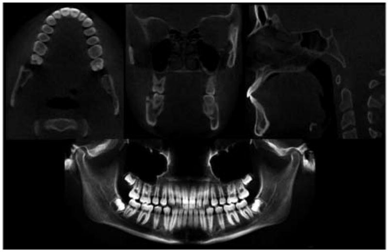
Axial, lateral (sagittal), and anteroposterior (coronal) cross-sections for each CT image acquisition. Using ITK-SNAP, we can scroll through 330 axial, 360 lateral, and 360 anteroposterior slices of volumetric data. NewTom 3G software also allows panoramic views.
FROM 2D SLICES TO 3D VIRTUAL MODELS
A key feature of CBCT images is the ability to navigate through the volumetric data set in any orthogonal slice window18 (axial, lateral, and anteroposterior views; Fig 2). Instead of just analyzing 2D cross-sectional images from a 3D patient, clinicians must think in 3D directions instead of 2D directions. From a set of more than 300 axial cross-sectional slices, it is possible to build 3D virtual models. The first step in image processing is to convert scanned images from DICOM (Digital Imaging and Communications in Medicine–standard for distributing any medical images regardless of scanner) to a format that allows the segmentation of anatomic structures. Image segmentation refers to the process of outlining the shape of structures visible in the cross-sections of a volumetric data set. After the segmentation, a 3D graphic rendering of the volumetric object allows navigation between voxels in the volumetric image and the 3D graphics with zooming, rotating, and panning (Figs 3 and 4). The National Institutes of Health has web pages to aid researchers in finding available image processing software.19 The image analysis tools we have used at the University of North Carolina Orthodontic Department for 3D superimpositions are open-source, freely available software systems.
Fig 3.
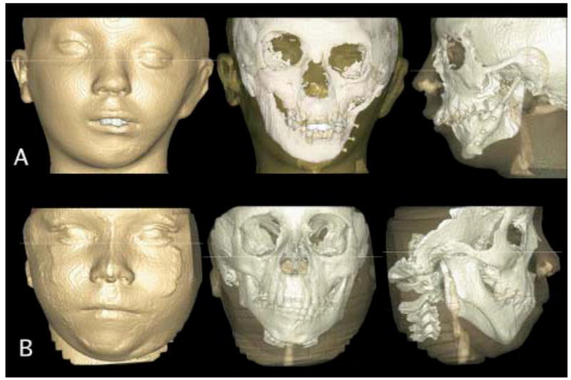
3D virtual models of 2 patients with hemifacial microsomia, showing segmentation of all slices stacked together without smoothing. A, Images acquired with 12-in field of view. Note costocondral graft establishing working condyle. B, Images acquired with 9-in field of view. Note significant asymmetry and missing articular fossa but presence of ramus and condyle on affected side. (Resolution is compromised by patient motion during acquisition; patient must remain still for 30 seconds after final alignment, and even swallowing can cause noise.)
Fig 4.
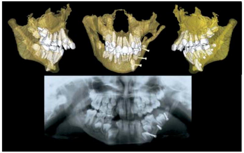
Transparency of bones allows visualization of developing permanent teeth. Panoramic x-ray suggested that surgical pins from graft might be impairing tooth eruption, but CBCT 3D models show that surgeon avoided tooth buds.
CBCT APPLICATIONS
Three-dimensional CBCT images provide additional diagnostic information on (1) size, shape, and position of mandibular condyle heads; (2) width of the tooth-bearing portion; (3) morphology, inclination, displacement, or deviation of the lateral and medial surfaces of the mandibular rami and body; (4) dental root positioning; (5) localization of impacted or supernumerary teeth; (6) palatal morphology; and (7) morphology of sites for placing implants or osteotomies. This information can help in identification of affected structures, treatment planning, and future comparisons with long-term follow-up of treatment stability (Figs 5 and 6).
Fig 5.
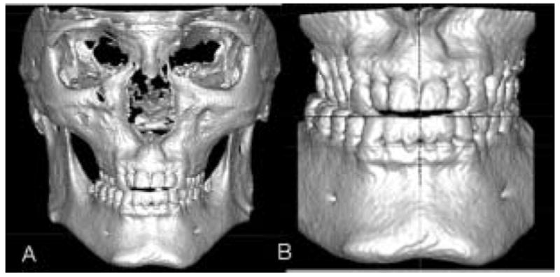
Conventional initial records suggested orthodontic treatment in conjunction with maxillary surgery for correction of cross-bite and anterior open-bite. A and B, 3D virtual models and display without posterior cortical bone show lingual tipping of maxillary premolars and molars. Patient was also offered orthodontic correction without surgery.
Fig 6.
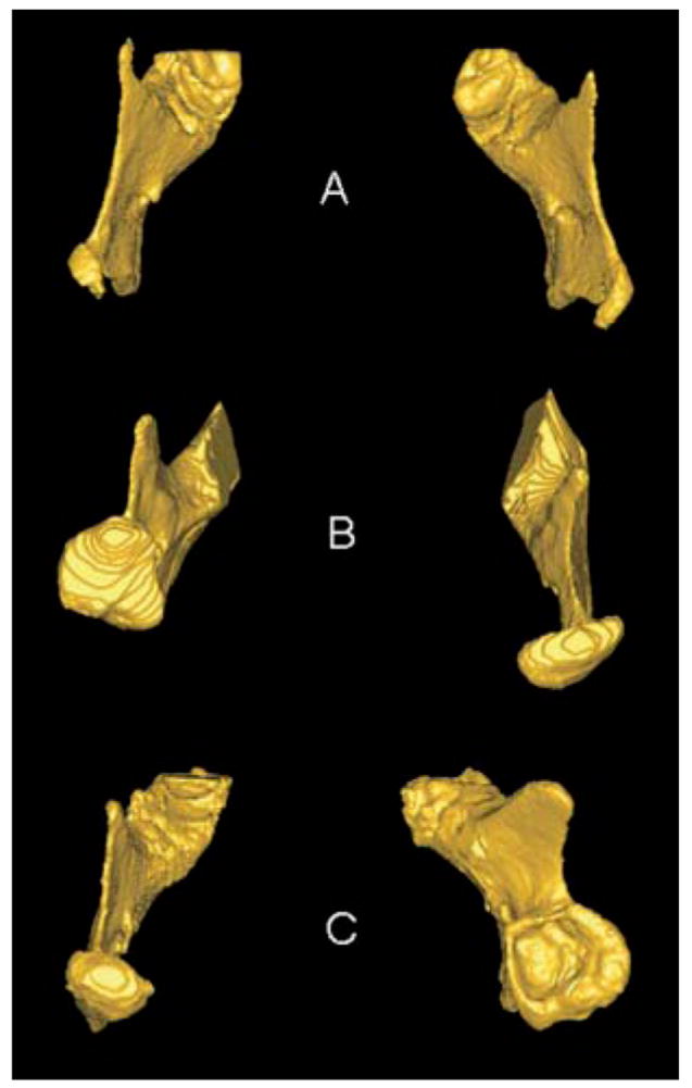
Superior views of 3D models of mandibular rami of 3 patients with condylar shape anomalies. A, Patient with idiopathic condylar resorption. B, Patient with left hemimandibular hypertrophy. C, Early right condylar fracture with abnormal growth of condyle around articular eminence.
The identification of the soft-tissue profile allows assessment of hard- and soft-tissue relationships. However, CBCT does not assess muscular morphology, and magnetic resonance imaging allows still more accurate renderings of the soft tissues.5,8,20,21 Caution is necessary in assessing the airway with NewTom 3G images versus the i-CAT, because the morphology of the airway space appears altered when the patient lies down for the NewTom acquisition (Fig 3).
An interesting capability of 3D models is to allow superimposition along the whole surface of the cranial base for adults or in the anterior cranial fossae for growing children. Although historically for 2D superimposition, we have used landmarks, planes, or 2D projections of surfaces, now software tools optimally align 3D CBCT data sets at different time points with subvoxel accuracy after identification of the cranial-base structures (Fig 7). The computed registration is then applied to the segmented structures to measure changes with time or treatment procedures.
Fig 7.
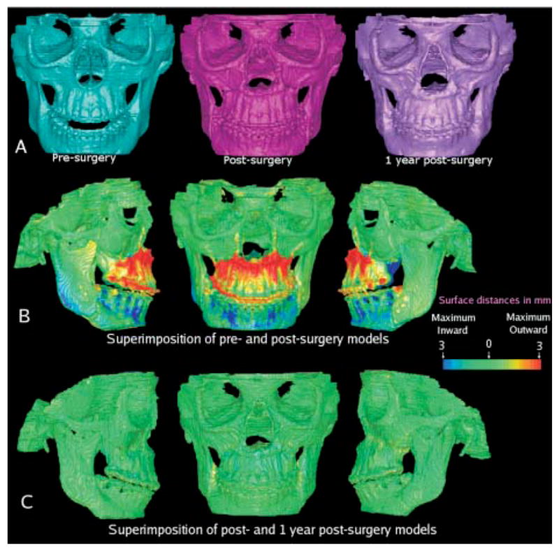
A, Presurgery, 1-week postsurgery, and 1-year postsurgery 3D models of patient treated with maxillary advancement and mandibular setback. B, Superimposition of pre- and postsurgery models showing surface distances between 2 models. Surface of cranial base was used for registration. Cranial base color map is green (0 mm surface distance), showing adequate match of before and after models for cranial base structures. Note that maxilla was brought forward as shown in red. Mandibular setback precisely maintained rami position, sliding mandibular corpus posteriorly, with slight counterclockwise rotation to correct open-bite tendency. C, Surface distances between 1-week and 1-year postsurgery models shows values close to 0 mm and stability of surgical procedures.
Image-analysis procedures include construction of 3D models,18 registration and superimposition of models at various time points,22 and calculation of the distances between the 3D surfaces.23 The automation of these methods, by using in-house computer tools, allows image analysis procedures to be largely independent of observer errors.24
The superimposition methods are fully automated, with voxel-wise rigid registration of the cranial base to avoid observer-dependent techniques based on overlap of anatomic landmarks. After the software masks the maxillary and mandibular structures, it compares the grey level intensity of each voxel in the cranial base to register the 2 CT images. These rotation and translation parameters are also applied to register 3D models. After registration, we can assess the overlay of the 3D models using Valmet.23
Valmet23 software allows visual and quantitative assessment of the location and magnitude of changes over time segmentation via graphic overlays and calculation of the distances between the surfaces of the 3D models at 2 time points (Fig 7). The resulting 3D graphic display of the structure is color-coded with the regional magnitude of the displacement between 2 segmentations. The pre- or postoperative segmentation results are overlaid on the CBCT image data for visual comparison. Semitransparency tools can be used for visualization of the 3D overlays (Fig 8).
Fig 8.

Semitransparent overlay of registered 1-week and 1-year postsurgery mandibular models of patient in Fig 7. Other anatomic structures are masked for better visualization of changes in mandible. Red, presurgery model; blue, area where pre- and postsurgery models overlap; green, postsurgery model.
Surface distance calculation can be applied to quantify displacement with growth and treatment.25 The calculation of surface distance for each boundary point is computationally expensive, because each contour point is compared with all the others. Valmet calculates all the 3D euclidean distances from the presurgery model to the overlaid postsurgery model, to measure the displacement. This measurement does not reflect properties integrated along the whole boundary and surface. For these reasons, the measurement of surface distances must be complemented by visualization of the 3D color-coded maps. The use of shape analysis and semilandmarks on the surface to incorporate information about vectors near the landmark will guide future research on 3D displacement with growth and treatment.
The visualization of 3D model superimposition and the surface distance calculations can be used to identify treatment outcomes and stability after treatment.20
Acknowledgments
Supported by NIDCR DE005215-26.
References
- 1.Halazonetis DJ. From 2-dimensional cephalograms to 3-dimensional computed tomography scans. Am J Orthod Dentofacial Orthop. 2005;127:627–37. doi: 10.1016/j.ajodo.2005.01.004. [DOI] [PubMed] [Google Scholar]
- 2.Hatcher DC, Aboudara CL. Diagnosis goes digital. Am J Orthod Dentofacial Orthop. 2004;125:512–5. doi: 10.1016/j.ajodo.2003.12.009. [DOI] [PubMed] [Google Scholar]
- 3.Mah J, Hatcher DC. Three-dimensional craniofacial imaging. Am J Orthod Dentofacial Orthop. 2004;126:308–9. doi: 10.1016/j.ajodo.2004.06.024. [DOI] [PubMed] [Google Scholar]
- 4.Hajeer MJ, Ayoub AF, Millett DT, Bock M, Siebert JP. Three-dimensional imaging in orthognathic surgery: the clinical application of a new method. Int J Adult Orthod Orthognath Surg. 2002;17:318–30. [PubMed] [Google Scholar]
- 5.Chirani RA, Jacq JJ, Meriot P, Roux C. Temporomandibular joint: a methodology of magnetic resonance imaging 3-D reconstruction. Oral Surg Oral Med Oral Pathol Radiol Endod. 2004;97:756–61. doi: 10.1016/j.tripleo.2004.02.073. [DOI] [PubMed] [Google Scholar]
- 6.Ono I, Ohura T, Narumi E, Kawashima K, Matsuno I, Nakamura S, et al. Three-dimensional analysis of craniofacial bones using three-dimensional computer tomography. J Craniomaxillofac Surg. 1992;20:49–60. doi: 10.1016/s1010-5182(05)80468-8. [DOI] [PubMed] [Google Scholar]
- 7.Nkenke EN, Zachow S, Benz M, Maier T, Veit K, Benz S, et al. Fusion of computed tomography data and optical 3D images of the dentition for streak artifact correction in the simulation of orthognathic surgery. Dentomaxillofacial Radiology. 2004;33:226–32. doi: 10.1259/dmfr/27071199. [DOI] [PubMed] [Google Scholar]
- 8.Kawamata A, Fujishita M, Kuniteru N, Kanematu N, Niwa K, Langlais R. Three-dimensional computed tomography evaluation of postsurgical condylar displacement after mandibular osteotomy. Oral Surg Oral Med Oral Pathol Oral Radiol Endod. 1998;85:371–6. doi: 10.1016/s1079-2104(98)90059-2. [DOI] [PubMed] [Google Scholar]
- 9.Harrell WE, Jr, Hatcher DC, Bolt RL. In search of anatomic truth: 3-dimensional digital modeling and the future of orthodontics. Am J Orthod Dentofacial Orthop. 2002;122:325–30. doi: 10.1067/mod.2002.126147. [DOI] [PubMed] [Google Scholar]
- 10.Miller AJ, Koutaro M, Hatcher DC. New diagnostic tools in orthodontics. Am J Orthod Dentofacial Orthop. 2004;126:395–6. doi: 10.1016/j.ajodo.2004.04.014. [DOI] [PubMed] [Google Scholar]
- 11.Xia J, Samman N, Yeung RWK, Shen SG, Wang D, Ip HHS, et al. Three-dimensional virtual reality surgical planning and simulation workbench for orthognathic surgery. Int J Adult Orthod Orthognath Surg. 2000;15:265–82. [PubMed] [Google Scholar]
- 12.Cevidanes LHS, Franco AA, Gerig G, Proffit WR, Slice DE, Enlow DH, et al. Assessment of mandibular growth and response to orthopedic treatment in 3-dimensional magnetic resonance images. Am J Orthod Dentofacial Orthop. 2005;128:16–26. doi: 10.1016/j.ajodo.2004.03.032. [DOI] [PubMed] [Google Scholar]
- 13.Cevidanes LHS, Franco AA, Gerig G, Proffit WR, Slice DE, Enlow DH, et al. Relative mandibular growth vectors using high resolution. Am J Orthod Dentofac Orthop. 2005;128:27–34. doi: 10.1016/j.ajodo.2004.03.033. [DOI] [PubMed] [Google Scholar]
- 14.Subsol G, Thirion JP, Ayache N. A scheme for automatically building three-dimensional morphometric anatomic atlases: application to skull atlas. Med Image Anal. 1998;2:37–60. doi: 10.1016/s1361-8415(01)80027-x. [DOI] [PubMed] [Google Scholar]
- 15.Andresen R, Bookstein FL, Conradsen K, Ersboll BK, Marsh JL, Kreiborg S. Surface-bounded growth modeling applied to human mandibles. IEEE Trans Med Imaging. 2000;19:1053–63. doi: 10.1109/42.896780. [DOI] [PubMed] [Google Scholar]
- 16.Mitteroecker P, Gunz P, Bookstein FL. Semilandmarks in three dimensions. In: Slice DL, editor. Modern morphometrics in physical anthropology. New York: Kluwer Academic Publishers; 2004. [Google Scholar]
- 17.Ludlow JB, Davies-Ludlow LE, Brooks SL. Dosimetry of two extraoral direct digital imaging devices: NewTom cone beam CT and Orthophos Plus DS panoramic unit. Dentomaxillofac Radiol. 2003;32:229–34. doi: 10.1259/dmfr/26310390. [DOI] [PubMed] [Google Scholar]
- 18.Yushkevich PA, Piven P, Hazlett HC, Smith RG, Ho S, et al. User-guided 3D active contour segmentation of anatomical structures: significantly improved efficiency and reliability. Neuroimage. 2006 doi: 10.1016/j.neuroimage.2006.01.015. in press. [DOI] [PubMed] [Google Scholar]
- 19. [February 9, 2006]; http://www.cc.nih.gov/cip/
- 20.Takács B, Pieper S, Cebral J, Kiss B, Benedek B, Szijártó G. SPIE Electronic Imaging. San Jose, Calif: 2004. Jan, Facial modeling for plastic surgery using magnetic resonance imagery and 3D surface data; pp. 18–22. [Google Scholar]
- 21.Heiland M, Habermann CR, Schmelze R. Indications and limitations of intraoperative navigation in maxillofacial surgery. J Oral Maxillofac Surg. 2004;62:1059–63. doi: 10.1016/j.joms.2004.02.013. [DOI] [PubMed] [Google Scholar]
- 22.Maes F, Collignon A, Vandermeulen D, Marchal G, Suetens P. Multimodality image registration by maximization of mutual information. IEEE Trans Med Imaging. 1997;16:187–98. doi: 10.1109/42.563664. [DOI] [PubMed] [Google Scholar]
- 23.Gerig G, Jomier M, Chakos M. Valmet: a new validation tool for assessing and improving 3D object segmentation. In: Niessen W, Viergever M, editors. MICCAI 2001: Proceedings of the International Society and Conference Series on Medical Image Computing and Computer-Assisted Intervention. Utrecht, Netherlands. Berlin: Springer; 2001. Oct 14-17, pp. 516–28. [Google Scholar]
- 24.Cevidanes LHS, Bailey LTJ, Tucker GR, Jr, Styner MA, Mol A, Phillips CL, et al. Superimposition of 3D cone-beam CT models of orthognathic surgery patients. Dentomaxillofac Radiol. 2005;34:369–75. doi: 10.1259/dmfr/17102411. [DOI] [PMC free article] [PubMed] [Google Scholar]
- 25.Cevidanes LHS, Bailey LTJ, Tucker SF, Styner MA, Mol A, Phillips CL, et al. Three-dimensional cone-beam CT for assessment of mandibular changes after orthognathic surgery. Am J Orthod Dentofacial Orthop. 2006 doi: 10.1016/j.ajodo.2005.03.029. in press. [DOI] [PMC free article] [PubMed] [Google Scholar]


