Abstract
Objectives
: The processes involved in the treatment of paraspinal tumours by volumetric modulated arc therapy (VMAT) are described here by means of an illustrative case.
Methods
: Az single anticlockwise arc from gantry angle 179° to 181° was constructed using SmartArc (Philips Radiation Oncology Systems, Fitchburg, WI) with control points spaced at 2°. The dose prescription was 60 Gy in 30 fractions to cover the planning target volume (PTV) as uniformly as possible while sparing the 0.3-cm planning risk volume (PRV) around the spinal cord. The plan was verified before treatment using a diode array phantom and radiochromic film. Treatment delivery was on a Synergy linear accelerator with a beam modulator head (Elekta Ltd, Crawley, UK).
Results
Homogeneous dose coverage of the PTV was achieved with a D2% of 62.0 Gy and D98% of 55.6 Gy. Maximum spinal cord dose was 49.9 Gy to 0.1 cm3 and maximum dose to the spinal cord PRV was 55.4 Gy to 0.1 cm3. At pre-treatment verification, the percentage of the high-dose region receiving a dose within 3% and 3 mm of the planned dose was 98.8% with the diode array and 93.4% with film. Delivery time was 2 min 15 s and the course of treatment was successfully completed.
Conclusions
VMAT was successfully planned, verified and delivered for this challenging tumour site. VMAT provides a very suitable method of treating complex paraspinal tumours, offering a high-quality conformal dose distribution with a short delivery time.
Introduction
Rotational radiotherapy techniques such as volumetric modulated arc therapy (VMAT) [1] are ideally suited to circularly symmetric target volumes. Paraspinal tumours fall within this class of volumes, with the spinal cord forming the axis of rotation and VMAT providing a uniform distribution of dose in the annular region around it [2]. There are reports in the literature on the use of VMAT for irradiation of spinal metastases [3-5] and re-irradiation of spinal metastases [6], but very little concerning primary paraspinal tumours. This article therefore describes the application of VMAT to primary paraspinal tumours by means of an illustrative case. Although the case relates to an unusual tumour histology and to an unusual patient position owing to significant spinal curvature, the tumour shape and the resulting VMAT planning and delivery processes are typical of paraspinal tumours. The processes of inverse treatment planning, pre-treatment verification and daily imaging are therefore described in detail as representative of a typical treatment.
Methods and materials
The patient forming the basis of this study initially presented with right shoulder pain in 2004. An MR investigation revealed a spinal tumour at the level of T2/3/4. The tumour consisted of both intradural and extradural components, both of which were excised surgically, the latter by a posterior extrapleural approach, in June 2004. The surgery was considered to be microscopically complete and the pathology was consistent with an infiltrative epithelioid schwannoma with neuroblastoma-like rosettes and a low mitotic rate (3 per 40 high-power fields) (World Health Organization Grade I). However, 5 years later the patient presented again with further pain in the right shoulder and leg weakness. Further MRI revealed an extensive recurrence with an intraspinal and intrathoracic component. The tumour was surgically debulked, with a limited intrathoracic component of the tumour being left behind. The pathology was identical to the initially removed tumour. 1 year later the tumour progressed again substantially, leading to increasing neuropathic pain. Based on the extent of the disease, the tumour was deemed unresectable by the neurosurgical, sarcoma and thoracic multidisciplinary teams. The patient was therefore referred for radical radiotherapy.
The patient was immobilised in a thermoplastic mask and CT scanned with contrast using a Brilliance scanner (Philips Medical Systems, Cleveland, OH). Three-dimensional T2 weighted MR images were also obtained with a 1.5 T Intera scanner (Philips Medical Systems) and the images were reformatted into transaxial orientation for radiotherapy planning. Image registration, contour delineation and treatment planning were then carried out on Pinnacle3 version 9.0 with SmartArc (Philips Healthcare, Fitchburg, WI) [7]. The gross tumour volume (GTV) and spinal cord were delineated on the MR images and lungs and oesophagus were delineated on the CT images. A 0.3-cm margin was added to the spinal cord to define a planning risk volume (PRV) [8]. The planning target volume (PTV) was then defined as the GTV plus 1 cm (1.5 cm superiorly and inferiorly) minus the spinal cord PRV. An annulus defined as the PTV plus a 3-cm margin, excluding the PTV itself, was also defined for inverse planning purposes.
The prescription for the treatment was to give a mean dose to the PTV of 60 Gy in 30 fractions. The treatment plan used a single anticlockwise VMAT arc from gantry angle 179° to gantry angle 181° with a collimator angle of 2° throughout. The anticlockwise rotation was chosen to provide convenient continuation after a clockwise cone-beam CT (CBCT) scan for patient set-up verification at the time of treatment. The control point spacing was 2° and the maximum delivery time was set to 80 s. By keeping the maximum delivery time fairly close to 60 s (the minimum possible time for a single complete arc), a degree of simplicity in the aperture shapes was maintained so as to ensure maximum accuracy in the dose calculation. Leaf motion was additionally constrained to a maximum rate of 0.8 cm per degree. The principal objectives used in the inverse planning are given in Table 1. Clinically, the goal was to achieve maximum PTV dose homogeneity, subject to a maximum dose of 50 Gy to 1 cm3 of the spinal cord and a maximum dose of 54 Gy to 1 cm3 of the spinal cord PRV. Dose was calculated using Pinnacle3's Adaptive Convolve option, which consisted of collapsed cone convolution with speed improvement by interpolating dose between every fourth grid point in regions of homogeneous dose. The resolution of the dose grid was 0.25×0.25×0.25 cm.
Table 1. Optimisation objectives.
| Structure | Objective | Importance weight |
| Planning target volume | Minimum dose 57 Gy | 1 |
| Maximum dose 61.5 Gy | 1 | |
| Uniform dose 60 Gy | 10 | |
| Spinal cord | Maximum dose 48 Gy | 10 |
| Spinal cord PRV | Maximum dose 51 Gy | 5 |
| Annulus | Maximum dose 56 Gy | 30 |
PRV, planning risk volume.
Prior to treatment, the dose distribution was verified using a Delta4 phantom (ScandiDos, Uppsala, Sweden). This consisted of a cylindrical polymethylmethacrylate phantom containing a total of 1069 diodes arranged in 2 orthogonal planes [9]. The dose was recalculated on an artificial CT scan representing the phantom, with a dose grid resolution of 0.2×0.2×0.2 cm and the plan was then delivered to the phantom. Planned and delivered doses were compared and the quality of the planned dose distribution was assessed using the proportion of measurements within 3% and 3 mm of the planned dose. For this comparison, 100% was considered to be a representative point in the high-dose region and all measurements above 20% were included. Owing to the proximity of the PTV to the spinal cord, additional film verification was carried out so as to verify the dose at all points along the involved length of the spinal cord. The plan was therefore recalculated on a volume representing a stack of Solid Water (Radiation Measurements Inc., Madison, WI) and then delivered to the same stack containing a sagittal EBT film (International Specialty Products, Wayne, NJ). The film was scanned using an Expression 1680 Pro flatbed film scanner (Epson Corporation, Suwa, Japan) and the density was converted into dose using in-house software written in Interactive Data Language (Research Systems, Inc, Boulder, CO) [10]. Planned and measured doses were compared using OmniPro I'mRT (Wellhöfer-Scanditronix, Schwarzenbrück, Germany). The measured dose was normalised to a point in the high-dose region and comparison of planned and measured dose was carried out for the area of the film receiving >50% of the normalisation dose.
The patient was treated on a Synergy digital linear accelerator (Elekta Ltd, Crawley, UK) with beam modulator head. The beam modulator consisted of 40 pairs of multileaf collimator leaves, each with a width of 0.4 cm at isocentre. Interdigitation of the leaves was possible and was taken advantage of by the optimiser during the inverse planning process. Daily CBCT imaging with online correction was carried out for the first 2 weeks of treatment and weekly imaging with offline correction was carried out thereafter.
Results
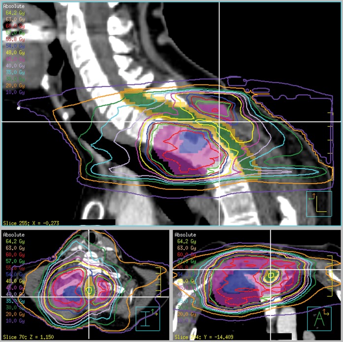
Figure 1 shows the dose distribution around the tumour, illustrating uniform coverage of the PTV with sparing of the spinal cord PRV. The intensity modulation enables close conformity of the isodoses to the PTV, particularly in the lung region, where the isodoses would in a simpler treatment spread out owing to the low lung density. The dose–volume histograms for the volumes of interest are shown in Figure 2. The maximum dose to 1 cm3 of the spinal cord was 48.4 Gy, meeting the clinical objective. The maximum dose to 0.1 cm3 of the spinal cord was 49.9 Gy, which corresponds to 1.66 Gy per fraction. If this was delivered in 2-Gy fractions and if the alpha/beta ratio for the spinal cord was 2-Gy, the equivalent dose according to the linear-quadratic model was 45.7 Gy. For the spinal cord PRV, the maximum dose to 1 cm3 was 53.4 Gy, again meeting the clinical objective. The maximum dose to 0.1 cm3 was 55.4 Gy, which corresponds to 53.3 Gy in 2 Gy fractions. Some compromise to the PTV dose was inevitably necessary in order to meet the spinal cord constraints, but only small regions of the PTV and GTV received 50–57 Gy. Specifically, D98% was 55.6 Gy, D95% was 57.6 Gy (i.e. 96% of the prescribed dose) and D2% was 62.0 Gy for the PTV. The irradiated volumes of lung and oesophagus are not likely to cause significant morbidity.
Figure 1.
Sagittal, transaxial and coronal views of the dose distribution. Blue, gross tumour volume; purple, planning target volume; green, spinal cord; orange, spinal cord planning risk volume. The white cross-hairs show the positions of the three orthogonal views. Note the considerable curvature of the patient's neck.
Figure 2.
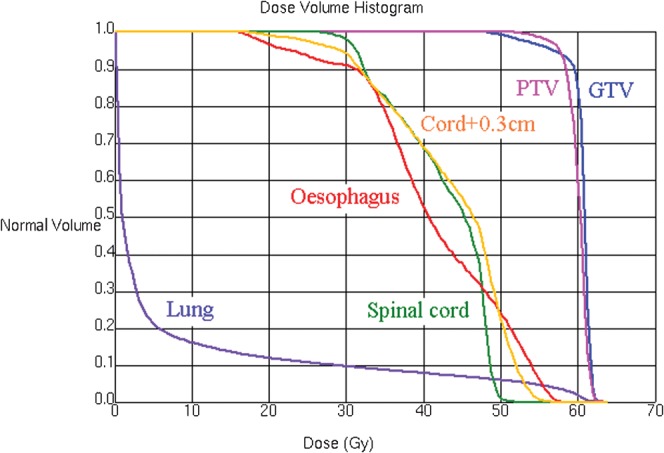
Dose–volume histograms for the volumes of interest. GTV, gross tumour volume; PTV, planning risk volume.
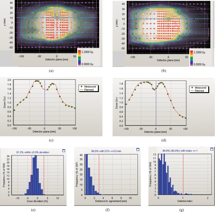
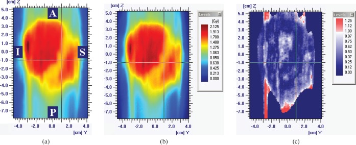
Figure 3 shows the result of the Delta4 verification. The dose agreement is good over the verified area and particularly in the vicinity of the spinal cord, as illustrated by the dose profiles. The gamma histogram [11] shown in Figure 3g indicates that 98.8% of the measured point doses agree with the planned dose to within 3% and 3 mm. The corresponding results for the film verification are shown in Figure 4. The gamma map shows agreement between measurements and calculations to within 3% and 3 mm over 93.4% of the region within the 50% isodose and in particular across the spinal cord region. The slightly lower gamma agreement obtained with film is considered to be a reflection of the slightly lower accuracy of film compared with calibrated diodes. Nevertheless, the Delta4 and film results are comparable.
Figure 3.
Delta4 verification results. (a,b) Planned dose distribution recalculated on the verification phantom (greyscale and isodoses), together with the delivered dose distribution (coloured circles) over the two planes of diodes. The colour legends apply to both the planned isodoses and the measured doses. (c,d) Dose profiles through the spinal cord region [see horizontal lines on (a) and (b)], with planned dose shown as a red line and measured dose shown as discrete green points. (e) Histogram of measured dose in relation to planned dose, (f) histogram of distance to agreement and (g) histogram of gamma for 3% and 3 mm, showing that 98.8% of measurements, i.e. greater than the required 90%, have a gamma of less than unity.
Figure 4.
Sagittal film verification results. (a) Planned dose distribution. (b) Delivered dose distribution. (c) Gamma for 3% and 3 mm, with gamma values of less than unity shown in blue and gamma values of greater than unity shown in red. 93.4% of measurements, i.e. greater than the required 90%, have a gamma of less than unity. A, anterior; I, inferior; P, posterior; S, superior.
The delivery time is 2 min 15 s for the single arc, which is valuable given the difficulty that the patient has in lying comfortably. This is a longer treatment time than predicted by the treatment planning system but is within ±1 min of the estimate, which is as accurately as can be predicted in practice. This delivery time compares with a time of around 7–10 min for a seven-field step-and-shoot intensity-modulated radiation therapy (IMRT) treatment which, in the absence of VMAT, would be needed to provide an equivalent dose distribution to that shown. VMAT therefore provides a comparable dose distribution to seven-field IMRT, but with a very much reduced treatment time.
The set-up errors pre- and post-correction are shown in Figure 5. The standard deviation of errors on all treatments post correction are <0.1 cm in any of the three axes, which shows that the patient is positioned reproducibly throughout the course of treatment.
Figure 5.
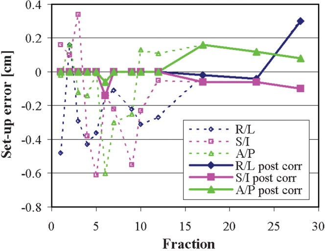
Daily set-up errors in the three orthogonal directions, as recorded by cone-beam imaging, pre-correction (dotted lines) and post-correction (solid lines). A/P, anterior/posterior; R/L, right/left; S/I, superior/inferior.
Conclusion
VMAT has been successfully applied to this challenging tumour site, providing a high-quality dose distribution with excellent sparing of the spinal cord. The verification measurements show that the treatment plan is dosimetrically accurate while the dynamic technique offers a fast treatment time, which in this case is important because of the difficulty that the patient has in lying flat and still. VMAT therefore appears to be indicated for paraspinal cases such as this. However, the proximity to the spinal cord necessitates careful attention to dosimetry and confidence that the immobilisation and image guidance are maintaining the PTV and spinal cord in the correct relative position.
Acknowledgments
Acknowledgments
The authors would like to thank Maria Schmidt for assistance with MR scanning; Clifford Knowles and Beverley Brigden for CT scanning; Young Lee, Corrinne Brooks and Michael Thomas for their assistance with the verification; Karen Aitken, Sally Eagle and Sarah Helyer for supervision of treatment; Paul Mayhew for assistance with engineering; and Jim Warrington for physics supervision. We are grateful to Elekta Ltd for their collaboration on VMAT and to Philips Medical Systems for their collaboration on adaptive radiotherapy.
Conflict of Interest
The authors collaborate with Elekta Ltd and Philips Medical Systems and receive research funding from Elekta Ltd.
Footnotes
We acknowledge NIHR funding to the NHS Biomedical Research Centre.
References
- 1.Yu CX, Tang G. Intensity-modulated arc therapy: principles, technologies and clinical implementation. Phys Med Biol 2011;56:R31–54 [DOI] [PubMed] [Google Scholar]
- 2.Zhang P, Happersett L, Yang Y, Yamada Y, Mageras G, Hunt M. Optimization of collimator trajectory in volumetric modulated arc therapy: development and evaluation for paraspinal SBRT. Int J Radiat Oncol Biol Phys 2010;77:591–9 [DOI] [PubMed] [Google Scholar]
- 3.Kuijper IT, Dahele M, Senan S, Verbakel WF. Volumetric modulated arc therapy versus conventional intensity modulated radiation therapy for stereotactic spine radiotherapy: a planning study and early clinical data. Radiother Oncol 2010;94:224–8 [DOI] [PubMed] [Google Scholar]
- 4.Mancosu P, Cozzi L, Fogliata A, Lattuada P, Reggiori G, Cantone MC, et al. Collimator angle influence on dose distribution optimization for vertebral metastases using volumetric modulated arc therapy. Med Phys 2010;37:4133–7 [DOI] [PubMed] [Google Scholar]
- 5.Wu QJ, Yoo S, Kirkpatrick JP, Thongphiew D, Yin F-F. Volumetric arc intensity-modulated therapy for spine body radiotherapy: comparison with static intensity-modulated treatment. Int J Radiat Oncol Biol Phys 2009;75:1596–604 [DOI] [PubMed] [Google Scholar]
- 6.Mancosu P, Navarria P, Bignardi M, Cozzi L, Fogliata A, Lattuada P, et al. Re-irradiation of metastatic spinal cord compression: a feasibility study by volumetric-modulated arc radiotherapy for in-field recurrence creating a dosimetric hole on the central canal. Radiother Oncol 2010;94:67–70 [DOI] [PubMed] [Google Scholar]
- 7.Bzdusek K, Friberger H, Eriksson K, Hårdemark B, Robinson D, Kaus M. Development and evaluation of an efficient approach to volumetric arc therapy planning. Med Phys 2009;36:2328–39 [DOI] [PubMed] [Google Scholar]
- 8.International Commission on Radiation Units and Measurements ICRU report 83: prescribing, recording, and reporting photon-beam intensity-modulated radiation therapy (IMRT). J ICRU 2010;10 [Google Scholar]
- 9.Bedford JL, Lee YK, Wai P, South CP, Warrington AP. Evaluation of the Delta4 diode array phantom for verification of IMRT and VMAT. Phys Med Biol 2009;54:N167–76 [DOI] [PubMed] [Google Scholar]
- 10.Thomas MDR, Warrington AP. GafChromic® RTQA film for routine quality assurance of high-energy photon beams. Phys Med Biol 2006;51:1439–47 [DOI] [PubMed] [Google Scholar]
- 11.Low DA, Harms WB, Mutic S, Purdy JA. A technique for the quantitative evaluation of dose distributions. Med Phys 1998;25:656–61 [DOI] [PubMed] [Google Scholar]


