Abstract
New energy industry including electric vehicles and large-scale energy storage in smart grids requires energy storage systems of good safety, high reliability, high energy density and low cost. Here a coated Li metal is used as anode for an aqueous rechargeable lithium battery (ARLB) combining LiMn2O4 as cathode and 0.5 mol l−1 Li2SO4 aqueous solution as electrolyte. Due to the “cross-over” effect of Li+ ions in the coating, this ARLB delivers an output voltage of about 4.0 V, a big breakthrough of the theoretic stable window of water, 1.229 V. Its cycling is very excellent with Coulomb efficiency of 100% except in the first cycle. Its energy density can be 446 Wh kg−1, about 80% higher than that for traditional lithium ion battery. Its power efficiency can be above 95%. Furthermore, its cost is low and safety is much reliable. It provides another chemistry for post lithium ion batteries.
The demand for electrical energy has significantly increased with the rapid growth of the global economy and population. Most of them are from fossil fuels, which produce large amount of greenhouse gases leading to environmental problems. There is a strong need for renewable energy such as solar, wind and tide energy, as well as safe and reliable energy storage systems (EES)1,2,3,4,5. In addition, for the further development of electric vehicles, battery systems with high safety and high energy density are urgently needed. It is well-known that the safety and the reliability for lithium ion batteries (LIBs) still prevent them from demonstrating for large-scale energy storage though they have quite some dominant advantages over traditional rechargeable batteries and the global has paid a lot to try to solve these still pending safety problems6,7. For the recent battery chemistries such as lithium/air, Li/S, Li/M+ and Na/S batteries, there are quite some challenges in terms of safety, reliability and cost7,8,9,10,11,12,13.
Aqueous rechargeable lithium batteries (ARLBs), which use aqueous electrolytes and lithium intercalation compounds as electrode(s) based on redox reactions, were invented in 199414 and have attracted wide attentions since 2007 as a promising system because of their low capital investment, high reliability and good safety15. Recent breakthroughs show clearly that they can present very good cycling performance and super-fast charge performance, which can be comparable with filling gasoline for engine cars16,17,18. Although several attempts have been made on the anode materials19,20,21, the main disadvantages is that their energy density is still much lower than that of conventional lithium ion batteries due to the narrow electrochemical window of water. If anode materials of lower redox potentials can be stable in aqueous electrolytes, high energy density systems will be feasible.
Here we introduce a coating layer on lithium metal. The coated lithium metal is stable in aqueous electrolytes. Combining with the coated lithium metal as anode, LiMn2O4 as cathode and 0.5 mol l−1 Li2SO4 aqueous solution as electrolyte, an ARLB is built up. Its average discharge voltage is about 4.0 V, much higher than the theoretic stable window of water, 1.229 V. It presents an energy density of 446 Wh kg−1 together with excellent cycling performance.
Results
The coated lithium metal is schematically shown in Figure 1. The coating consists of a home-made gel polymer electrolyte (GPE) and a LISICON film. LISICON film is a solid electrolyte which can also act as a separator. Its ionic conductivity of Li+ ions is about 0.1 mS cm−1 at room temperature. Due to its solid structure, protons, water, hydrated and solvated ions cannot pass through11,12,22. The GPE consists of a sandwiched structured PVDF/PMMA/PVDF absorbing with an organic electrolyte (1 mol l−1 LiClO4 solution in ethylene carbonate, diethyl carbonate and dimethyl carbonate, volume ratio is 1:1:1) and is stable with Li metal. Its ionic conductivity of Li+ ions can be the same level of separators saturating with the liquid electrolyte, about 0.2 mS cm−1 at room temperature. If LISICON film contacts with Li metal, some metal oxides such as GeO2 in the LISICON film will be reduced by Li metal leading to poor ionic conductivity. As a result, the GPE ensures the good electrochemical stability of the LISICON film, and only Li+ ions can transfer between Li metal and the outside via the LISICON film and the GPE11,23. The coated lithium metal is very stable in aqueous electrolytes. When it was dipped in 0.5 mol l−1 Li2SO4 aqueous solution over one week, hydrogen gas could not be detected.
Figure 1. The schematic illustration of the coated lithium metal: GPE represents a gel polymer electrolyte consisting of a sandwiched polymer membrane, PVDF/PMMA/PVDF, saturating with 1 mol l−1 LiClO4 solution in ethylene carbonate, diethyl carbonate and dimethyl carbonate (volumetric ratio is 1:1:1), and LISICON film refers to a solid film consisting of Li2O-Al2O3-SiO2-P2O5-TiO2-GeO2.
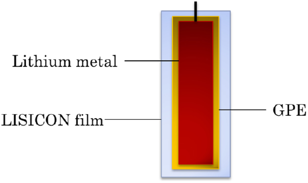
The shape of Li metal is square with 2 mm (width) × 5 mm (length) × 0.5 mm (thickness).
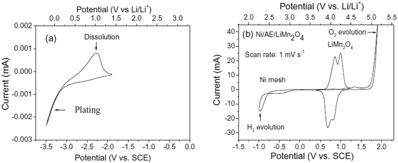
The CV curve of the coated lithium metal, Ni mesh and LiMn2O4 obtained in 0.5 mol l−1 Li2SO4 aqueous solution using Ni mesh as the counter electrode and saturated calomel electrode (SCE) as the reference electrode is shown in Figure 2. It presents clearly that Li atom can lose one electron to produce Li+ ion, which passes through the GPE and the LISICON film, then into the aqueous electrolyte. Reversibly Li+ ion in the aqueous electrolyte can pass through the LISICON film and the GPE and get one electron to produce Li atom at the surface of the lithium metal.
Figure 2. CV curves in the first scan of (a) the coated lithium metal at the scan rate of 0.1 mV s−1, and (b) LiMn2O4 and Ni mesh at the scan rate of 1 mV s−1 in 0.5 mol l−1 Li2SO4 aqueous electrolyte (AE) using SCE as the reference electrode.
All the scans started from the lower potential and shifted to the positive potential and then back to the lower potential.
In the case of LiMn2O4, as shown in Figure 2b there are two redox couples at the scan rate of 1 mV s−1, which are situated at 0.86/0.68 V and 1.00/0.83 V (vs. SCE), respectively. These redox peaks correspond to the de-intercalation and intercalation of Li+ ions from/into the spinel host structure in the aqueous electrolyte16,17. Their potentials are much lower than the oxygen evolution potential at the Ni mesh surface, 1.7 V (vs. SCE). This also means that overpotentials can extend the electrochemical stable window of water and LiMn2O4 is very stable for the reversible de-intercalation/intercalation reaction in the aqueous electrolyte. These results show clearly that both the coated lithium metal and LiMn2O4 are stable in the aqueous electrolyte for reversible redox reactions and the difference of their redox potentials is very large, their combination will build up a rechargeable battery system.
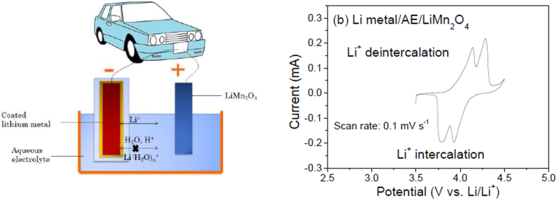
The schematic structure of the assembled aqueous rechargeable lithium battery (ARLB) using the coated lithium metal as the anode and LiMn2O4 as the cathode and its CV curve at the scan rate of 0.1 mV s−1 are shown in Fig. 3. There are two couples of redox peaks situated at 4.14/3.80 and 4.28/3.93 V, respectively. From the above illustration, the redox reactions are as follows:
During charging, there is only one reaction at the anode. Li+ ions from the aqueous electrolyte solution transport through the coating layer, are reduced at the surface of lithium metal and deposited as Li metal. At the cathode two reactions proceed: Li+ cations de-intercalate from the tetrahedral 8a- and octahedral 16c-sites, subsequently, causing two redox couples (Figure 2b), similar to the behavior in organic electrolytes7. During the discharge process, the reverse processes take place. Consequently, in the CV curve of our ARLB there are two redox couples. This indicates that our above battery chemistry of coated lithium metal/0.5 mol l−1 Li2SO4/LiMn2O4 can work as a rechargeable battery in the aqueous electrolyte at an average output voltage above 3.8 V, much higher than the theoretical decomposition voltage of water, i.e. 1.229 V.
Figure 3. (a) Schematic illustration of our designed aqueous rechargeable lithium battery (ARLB) using the coated lithium metal as anode, LiMn2O4 as cathode and 0.5 mol l−1 Li2SO4 aqueous solution as electrolyte, and (b) CV of the ARLB at the scan rate of 0.1 mV s−1.
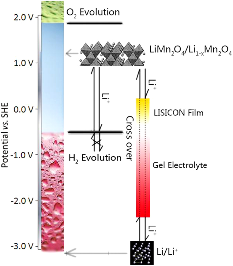
The potential change of Li+ ions in our designed ARLB is shown in Figure 4. Lithium metal has the lowest redox potential, −3.05 V (vs. standard hydrogen electrode, SHE), and rapidly reacts with water and produce hydrogen and LiOH. In addition, the potential of lithium metal is much lower than that for hydrogen evolution, hydrogen will easily produce. However, in our case, the coated lithium metal is very stable in the aqueous electrolyte and there is no hydrogen evolution. The main reason is that Li+ ions can cross over the hydrogen evolution potential range through the coating and arrive at the lithium metal directly. This cross-over is similar to the potential change between both sides of a cell membrane24. In the coating the potential of Li+ ions decreases very sharply from the positive to the negative. The Li+ ions at the outside of the coating have higher potential and are very stable. The Li+ ions at the inside of the coating do not contact with water, the atomic Li could not give electron to water leading to production of hydrogen. By the way, water and protons could not enter into the inside of the coating, they could not arrive at enough low potential to produce hydrogen. As to the LiMn2O4 cathode, it is stable in water since its potential is below that for the oxygen evolution and much higher than that for hydrogen evolution.
Figure 4. Schematic illustration of the potential of Li+ ions during the movement between LiMn2O4 in the aqueous electrolyte and the coated lithium metal.
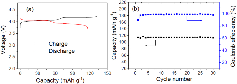
The electrochemical performance of the ARLB between 3.7 and 4.25 V is shown in Figure 5. In the galvanostatic charge curve of the ARLB at a current density of 100 mA g−1 based on the mass of LiMn2O4 there are two distinct voltage plateaus at 4.04 and 4.18 V. During the discharge process, the two voltage plateaus appear at 4.07 and 3.94 V, respectively. This is in good agreement with the two couples of redox peaks observed in the above CV curve and consistent with the de-intercalation and intercalation of Li+ ions from and into the spinel LiMn2O4. The average discharge voltages are about 4.0 V, 0.2 V higher than those of lithium ion batteries based on LiMn2O4 cathodes and graphitic carbon anodes. The energy efficiency based on the discharge and charge voltages will be above 95%, higher than those for lithium ion batteries (about 90%) and other battery systems12,22,25. The initial charge and discharge capacities of this battery based on the mass of LiMn2O4 are 130 and 115 mAh g−1, respectively, and the initial Coulomb efficiency is 88.5%. These values are similar to those in the organic electrolyte7. The capacity is much higher than that for the new liquid cathode based on  -solution12. Of course, in lithium ion batteries using organic electrolytes, LiMn2O4 should be doped or coated to ensure its good cycling performance26, and its reversible capacity is below 110 mAh g−1. Here LiMn2O4 does not need doping or coating16,17, and the specific capacity of LiMn2O4 in the ARLB is practically higher than that in the organic electrolytes.
Figure 5. Electrochemical performance of our designed ARLB at the current density of 100 mA g−1 based on the mass of LiMn2O4 between 3.7 and 4.25 V: (a) Galvanostatic charge-discharge curves in the first cycle and (b) cycling behavior.
Based on the discharge voltages and the capacities of the Li metal anode and LiMn2O4 cathode, the discharge energy density of the ARLB based on the total mass of the electrode materials is 446 Wh kg−1, much higher than those for the formerly reported ARLBs (30–45 Wh kg−1)14,15,16,17,18,19,20,21. Of course, it is higher than that for Li/aqueous M+ and the other redox flow batteries3,4,5,9,12. Based on the manufacturing technologies of lithium ion batteries, half of the energy density can be made practically available7,14, which means that the practical energy density will be above 220 Wh kg−1, about 80% higher than that for the corresponding Li-ion batteries for electric vehicles (120 Wh kg−1 for C/organic electrolyte/LiMn2O4)6,7. This high energy density indicates that a pure electric vehicle can run 200–400 km for one charge.
During the cycling at the current density of 100 mA g−1 based on the mass of LiMn2O4 the Coulomb efficiency of the ARLB is nearly 100% except for the first cycle, which is similar to that for lithium ion batteries. This high Coulomb efficiency also indicates that water is very stable and there is no evident side reaction for protons or water. After 30 full cycles, the discharge capacity still stays very stable at the around of 115 mAh g−1, which means no obvious capacity fading occurred in the first 30 cycles. This suggests that the cycling behavior of this battery chemistry is very excellent, which is similar to that of LiMn2O4 in the traditional ARLBs (see Figure S4a in the Supporting information: no evident capacity fading after 200 cycles for this LiMn2O4 cathode). In the latter case, LiMn2O4 can retain 93% capacity after 10000 full cycles, which is superior to other kinds of rechargeable batteries16,17. As to the Li metal, the polymer electrolyte can buffer the volume change during dissolution and plating, which ensures its good contact with the coating. This is also important to achieve excellent cycling performance.
Discussion
In the conventional lithium metal secondary batteries, the use of Li metal as anode material is restricted by the safety problems because lithium dendrites will form during repeated charge-discharge process leading to short circuiting6,7. In our design as shown in Figure 1, lithium metal is coated by the GPE and LISICON film. The formation of lithium dendrites will be inhibited in the GPE27 due to its higher viscosity than those of the organic liquid electrolytes. Even when lithium dendrites are formed, they cannot grow through the LISICON film11,12,22. As a result, the safety and the cycling behavior of the Li metal anode are ensured.
In this ARLB system, the aqueous electrolyte has high thermal capacitance and can absorb large amounts of heat. During the same charge and discharge process, the temperature of this system will be much lower than that for conventional lithium ion batteries. In addition, water or aqueous electrolyte is in direct contact with both of the Li metal anode and the LiMn2O4 cathode, and the cooling effects will be very efficient. The cooling system, which is usually needed for large capacity battery modules, is not needed for the application in electric vehicles. The safety and reliability is greatly improved when compared with conventional lithium ion batteries.
Under some abuse conditions, if the coating of GPE and LISICON film is broken, water will contact with Li metal. In the aqueous electrolyte, there is enough lithium salt. The reaction will produce insoluble LiOH layer on the surface of lithium metal and prevent the further reaction. By the way, the produced hydrogen will pass through the aqueous electrolyte and be cooled down. It is difficult for it to get on fire. In addition, the produced hydrogen is very light and will be very easy to dissipate into the atmosphere. The content of hydrogen will be very small to cause fire or explosion. This is different from the behavior of the organic electrolyte, which are heavier than air. The produced organic gases at extreme conditions could not escape from the around of the lithium ion batteries very quickly, and fire and/or explosion easily happen.
The effect of this ARLB chemistry to the environment is very friendly since it avoids the use of LiPF6, which produces caustic and dangerous HF upon contact with water. So far there is rare report about the attempts to recycle this salt from used lithium ion batteries. It does not need other unfriendly materials, either.
It is well known that to avoid the water decomposition at a voltage up to 4.25 V is very rarely reported. In the case of lead acid rechargeable batteries, the voltage can be only up to 2.2 V due to the overpotentials from the lead, which retard the evolution of hydrogen and oxygen gases. In our ARLB system, the main reason, as mentioned above, is due to the “cross-over” effects of Li+ ions in the coating. This is different from the traditional methods to utilize overpotentials. It is similar to the cell membrane, which presents quite different potential at the outside and inside of the cells due to the membrane effects24. The stability of this high voltage battery system is evident after storage at the fully charged state for 60 days. No hydrogen and extra oxygen can be observed or detected.
In terms of the anode and cathode materials, this system is similar to the well-known rechargeable Li/LiMn2O4 battery using organic electrolytes, which has a serious safety problem from Li dendrites and poor cycling performance from LiMn2O4 (see Figure S4b in the Supporting information) due to the Jahn-Teller effect and Mn dissolution7,26. As discussed above, our ARLB system protects against the birth of conceivable Li dendrites. LiMn2O4 also presents very excellent cycling performance in the aqueous electrolyte even the Jahn-Teller effect still exists. The main reason is that there is no acid like HF in the neutral Li2SO4 aqueous solution, which will lead to the dissolution of Mn element16,17. The content of proton in the neutral aqueous electrolyte is about 10−7 mol l−1 (10−4 ppm), much less than that in the organic electrolyte, at least 10 ppm.
Compared with most recently developed Li/air batteries, this ARLB presents at least the following evident advantages11,12,27,28: (1) Much better cycling performance. In the case of Li/air, the reported data are only several full cycles with serious capacity fading; (2) Higher practical energy density. No matter whether LiOH or Li2O2, their solubility in the aqueous or organic electrolytes is quite small. The practical energy density calculated on the basis of their dissolution will be less than 200 Wh kg−1; (3) Higher energy efficiency. According to the latest report, the lowest overpotential between average charge and discharge voltages for Li/air is still above 0.8 V, and its energy efficiency will not be above 80%27,28.
Of course, the manufacturing technologies for all materials for this ARLB including LiMn2O4, LISION film, GPEs and Li metal are well-known. The production cost will be cheaper than that for convention lithium ion batteries. Furthermore, the cycling performance of the ARLB is much better than that of lithium ion batteries even compared with the chemistry of graphite/organic electrolyte/LiFePO4.
For further work, LiCoO2 and Li[NixCoyMn1−x−y]O2 can replace LiMn2O4 to get higher energy density. For example, the reversible capacity of LiCoO2 in the aqueous electrolyte can be 143 mAh g−1 and its average discharge voltage is 0.90 V (vs. SCE) corresponding to 4.19 V (vs. Li/Li+)18. Based on this ARLB design, the energy density on the basis of the electrode materials can be above 570 Wh kg−1, and the estimated practical energy density will be above 285 Wh kg−1. When Li[NixCoyMn1−x−y]O2, which presents a reversible capacity of 160 mAh g−1 in aqueous electrolytes29, is used as the cathode for this ARLB, the estimated practical energy density will be above 300 Wh kg−1. Based on these data, it means that this new ARLB chemistry can ensure electric vehicles to run above 300 km for one charge, which presents great promise.
In summary, an aqueous rechargeable lithium battery (ARLB) using a coated lithium metal as anode and LiMn2O4 as cathode is established. Due to the “cross-over” effect, lithium ions at the higher potential side in the aqueous electrolyte can pass through the coating and arrive at the lower potential side of lithium metal. As a result, the coated lithium metal is very stable in the aqueous electrolyte and the average output voltage of this ARLB is 4.0 V. Its energy density is 80% higher than that of conventional lithium ion batteries and much higher than practical values of Li/air. Its energy efficiency is above 95%. Its cycling behavior is also very excellent. Furthermore, its cost is low and safety including environmental safety is much high and reliable. This ARLB system opens another chemistry for the new energy industry such as electric vehicles and large-scale energy storage in smart grids.
Methods
Anode
Li metal (square: 2 mm × 5 mm × 0.5 mm of width, length and thickness) was at first simply coated (like casing) by a home-made gel polymer electrolyte (GPE), whose ionic conductivity is about 0.2 mS cm−1 at room temperature. The GPE was made by saturating a sandwiched polymer membrane, PVDF (poly(vinyl difluoride))/PMMA (poly(methyl methacrylate))/PVDF, of 50 μm with the 1 mol l−1 LiClO4 solution in ethylene carbonate, diethyl carbonate and dimethyl carbonate (volumetric ratio is 1:1:1)23. Then, a LISICON film consisting of Li2O-Al2O3-SiO2-P2O5-TiO2-GeO2, which was bought from Ohara Inc., Japan, was further simply put on the GPE. Thickness and ionic conductivity of the LISICON film are 150 μm and 0.1 mS cm−1 at room temperature, respectively.
Cathode
The LiMn2O4 was prepared by a starch-assisted sol–gel method as our previously reported, which exists in the nanochain morphology16. Further details are described in the Supporting information. The cathode electrode was prepared by pressing a mushy mixture of the as-prepared LiMn2O4, acetylene black and poly(tetrafluoroethylene) (PTFE) (in a weight ratio of 7.5:1.5:1) dispersed in ethanol onto a Ni-grid. After drying, the mixture was pressed into a film, and then the film was cut into disks of about 1.5 mg and 0.4 cm2. These disks were pressed onto a Ni-grid at a pressure of 10 MPa and then dried at 80°C overnight to act as cathodes.
Electrochemical test
Aqueous Li2SO4 solution (0.5 mol l−1) was used as the electrolyte. Cyclic voltammetry (CV) was performed at a scan rate of 0.1 mV s−1 using an electrochemical work station (CHI660C, Shanghai). For the cathode, the test was performed using a three-electrode cell, where activated carbon and saturated calomel electrode (SCE, 0.242 V vs. SHE: standard hydrogen electrode) were used as the counter and reference electrodes, respectively. For the anode, the test was performed using Ni mesh and SCE as the counter and reference electrodes, respectively. The voltage during galvanostatic charge-discharge tests for the total battery was between 3.7 and 4.25 V using a Land cycler (Wuhan, China).
Assembling of the ARLB
The coated Li metal anode and the LiMn2O4 cathode were dipped into 0.5 mol l−1 aqueous Li2SO4 solution, and their distance is about 1 cm.
Author Contributions
Y.W. proposed the conceptual idea, participated in the analysis of results, discussing and writing the manuscript, and provided financial support through grant application. X.W. prepared the ARLB and tested its performance. H.Y. prepared the cathode, Y.Z. prepared the sandwiched membrane. R.H. participated in discussing the results and in writing the manuscript. All authors read and approved the final manuscript.
Supplementary Material
An Aqueous Rechargeable Lithium Battery Using Coated Li Metal as Anode
Acknowledgments
Financial support from MOST (2010DFA61770), STCSM (12JC1401200), NSFC (21073046) and Humboldt Foundation (Partnership Program) is greatly appreciated.
References
- Dunn B., Kamath H. & Tarascon J. M. Electrical energy storage for the grid: a battery of choices. Science 334, 928–935 (2011). [DOI] [PubMed] [Google Scholar]
- Yang Z. & Zhang G. et al. Electrochemical energy storage for green grid. Chem. Rev. 111, 3577–3613 (2011). [DOI] [PubMed] [Google Scholar]
- Ponce de León C., Frías-Ferrer A., González-García J., Szánto D. A. & Walsh F. C. Redox flow cells for energy conversion. J. Power Sources 160, 716–732 (2006). [Google Scholar]
- Jia C. K., Liu J. G. & Yan C. W. A multilayered membrane for vanadium redox flow battery. J. Power Sources 203, 190–194 (2012). [Google Scholar]
- Xi J. Y. et al. Self-assembled polyelectrolyte multilayer modified Nafion membrane with suppressed vanadium ion crossover for vanadium redox flow batteries. J. Mater. Chem. 18, 1232–1238 (2008). [Google Scholar]
- Tarascon J. M. & Armand M. Issues and challenges facing rechargeable lithium batteries. Nature, 414, 359–367 (2001). [DOI] [PubMed] [Google Scholar]
- Wu Y. P., Yuan X. Y., Dong C. & Duan J. Y. Lithium ion batteries: Applications and Practice (2nd Edition). Chemical Industry Press, Beijing, 2012. [Google Scholar]
- Ji X. L., Evers S., Black R. & Nazar L. F. Stabilizing lithium-sulphur cathodes using polysulphide reservoirs. Nat. Commun. 2, 325 (2011). [DOI] [PubMed] [Google Scholar]
- Wessells C. D., Huggins R. A. & Cui Y. Copper hexacyanoferrate battery electrodes with long cycle life and high power. Nat. Commun. 2, 550 (2011). [DOI] [PubMed] [Google Scholar]
- Hayashi A., Noi K., Sakuda A. & Tatsumisago M. Superionic glass-ceramic electrolytes for room-temperature rechargeable sodium batteries. Nat. Commun. 3, 856 (2012). [DOI] [PubMed] [Google Scholar]
- Zhang T. et al. A novel high energy density rechargeable lithium/air battery. Chem. Commun. 46, 1661–1663 (2010). [DOI] [PubMed] [Google Scholar]
- Lu Y. H., Goodenough J. B. & Kim Y. Aqueous cathode for next-generation alkali-ion batteries. J. Am. Chem. Soc. 133, 5756–5759 (2011). [DOI] [PubMed] [Google Scholar]
- Wang W. et al. Anthraquinone with tailored structure for a nonaqueous metal-organic redox flow battery. Chem. Commun. 48, 6669–71 (2012). [DOI] [PubMed] [Google Scholar]
- Wu L., Dahn J. R. & Wainwright D. S. Rechargeable lithium batteries with aqueous electrolytes. Science 264, 1115–1117 (1994). [DOI] [PubMed] [Google Scholar]
- Wang G. J. et al. An aqueous rechargeable lithium battery with good cycling performance. Angew. Chem. Int. Ed 46, 295–297 (2007). [DOI] [PubMed] [Google Scholar]
- Tang W. et al. Nanochain LiMn2O4 as ultra-fast cathode material for aqueous rechargeable lithium batteries. Electrochem. Commun. 13, 205–208 (2011). [Google Scholar]
- Qu Q. T. et al. High-rate and long-life LiMn2O4 cathode for aqueous rechargeable lithium batteries. Energ. Environ. Sci. 4, 3985–3990 (2011). [Google Scholar]
- Tang W. et al. Nano-LiCoO2 as cathode material of large capacity and high rate capability for aqueous rechargeable lithium batteries. Electrochem. Commun. 12, 1524–1526 (2010). [Google Scholar]
- Tang W. et al. An aqueous rechargeable lithium battery of excellent rate capability based on nanocomposite of MoO3 coated with PPy and LiMn2O4. Energy Environ. Sci. 5, 6909–6913 (2012). [Google Scholar]
- Tang W. et al. Coated hybrid of V2O5 nanowires with MWCNTs by polypyrrole as anode material for aqueous rechargeable lithium battery with excellent cycling performance. J. Mater. Chem. 22, 20143–20145 (2012). [Google Scholar]
- Luo J. Y., Cui W. J., He P. & Xia Y. Y. Raising the cycling stability of aqueous lithium–ion batteries by eliminating oxygen in the electrolyte. Nat. Chem. 2, 760–765 (2010). [DOI] [PubMed] [Google Scholar]
- Li H. Q., Wang Y. G., Na H. T., Liu H. M. & Zhou H. S. Rechargeable Ni-Li battery integrated aqueous/nonaqueous system. J. Am. Chem. Soc. 131, 15098–15099 (2009). [DOI] [PubMed] [Google Scholar]
- Zhang H. P. et al. A novel sandwiched membrane as polymer electrolyte for lithium ion battery. Electrochem. Commun. 9, 1700–1703 (2007). [Google Scholar]
- Colacicco G. Reversal of potential across a liquid nonaqueous membrane with regard to membrane excitability. Nature 207, 1045–1047(1965). [DOI] [PubMed] [Google Scholar]
- Abouimrane A. et al. A new class of lithium and sodium rechargeable batteries based on selenium and selenium-sulfur as a positive electrode. J. Am. Chem. Soc. 134, 4505–4508 (2012). [DOI] [PubMed] [Google Scholar]
- Fu L. J. et al. Electrode materials for lithium secondary batteries prepared by sol-gel methods. Prog. Mater. Sci. 50, 881–928 (2005). [Google Scholar]
- Chen Y. H. et al. Li-O2 battery with a dimethylformamide electrolyte. J. Am. Chem. Soc. 134, 7952–7957 (2012). [DOI] [PubMed] [Google Scholar]
- Peng Z., Freunberger S. A., Chen Y. H. & Bruce P. G. A reversible and higher-rate Li-O2 battery. Science 337, 563–5663 (2012). [DOI] [PubMed] [Google Scholar]
- Zheng J. et al. Electrochemical performance of the LiNi1/3Co1/3Mn1/3O2 in aqueous electrolyte. J. Electrochem. Soc. 157, A702–A706 (2010). [Google Scholar]
Associated Data
This section collects any data citations, data availability statements, or supplementary materials included in this article.
Supplementary Materials
An Aqueous Rechargeable Lithium Battery Using Coated Li Metal as Anode


