Abstract
Enhanced Depth Imaging (EDI) optical coherence tomography (OCT) provides high-definition cross-sectional images of the choroid in vivo, and hence is used in many clinical studies. However, the quantification of the choroid depends on the manual labelings of two boundaries, Bruch’s membrane and the choroidal-scleral interface. This labeling process is tedious and subjective of inter-observer differences, hence, automatic segmentation of the choroid layer is highly desirable. In this paper, we present a fast and accurate algorithm that could segment the choroid automatically. Bruch’s membrane is detected by searching the pixel with the biggest gradient value above the retinal pigment epithelium (RPE) and the choroidal-scleral interface is delineated by finding the shortest path of the graph formed by valley pixels using Dijkstra’s algorithm. The experiments comparing automatic segmentation results with the manual labelings are conducted on 45 EDI-OCT images and the average of Dice’s Coefficient is 90.5%, which shows good consistency of the algorithm with the manual labelings. The processing time for each image is about 1.25 seconds.
OCIS codes: (100.0100) Image processing, (110.4500) Optical coherence tomography, (100.2960) Image analysis, (170.4470) Ophthalmology
1. Introduction
The choroid (lying between the retina and the sclera as shown in Fig. 1), also known as choroidea and or choroid coat, is the vascular layer of the eye. It provides the metabolic support to the retinal pigment epithelium (RPE), supplies blood to the optic nerve and absorbs the excess light penetrating the retina [1]. The quantitative and qualitative evaluation of the choroid is important in order to reveal its relationship with the retinal diseases and glaucoma. Quigley et. al proposed that a mere 50 micrometer choroid expansion in angle closure glaucoma patients can increase the intraocular pressure to harmful levels [2]. There has also been an increasing interest in investigating its correlation with the age, gender, axial length and intra-ocular pressure in healthy human eyes [3–5].
Fig. 1.
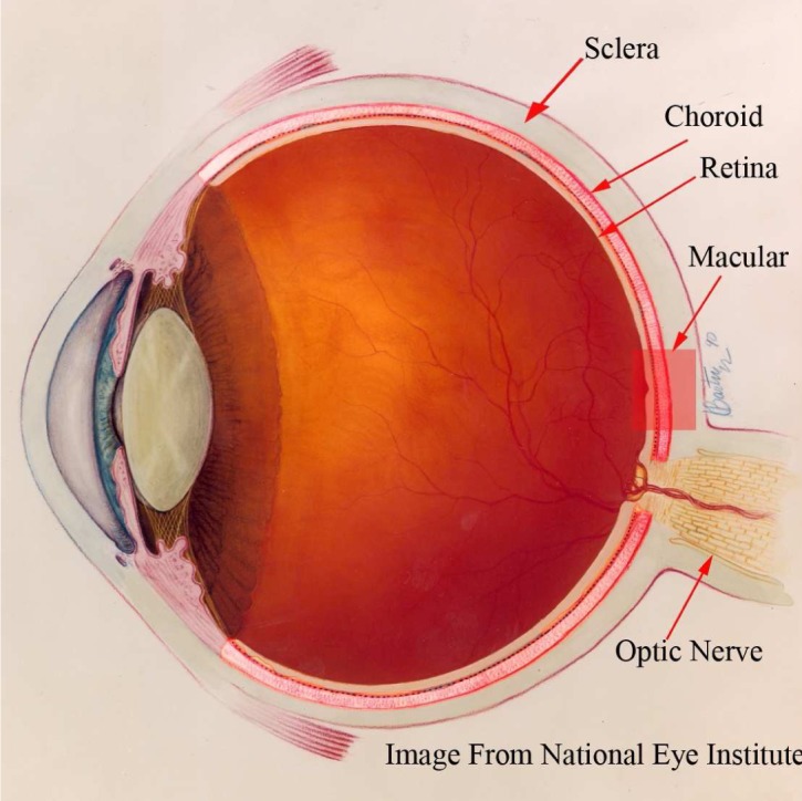
Anatomy of the human eye: the choroid is the vascular layer between the sclera and the retina. Image courtesy of the National Eye Institute, National Institute of Health.
Therefore, the research on measuring the choroidal thickness in vivo has attracted the attention of many clinicians and scientists. Traditionally, histological evaluation is used but the measurement is not accurate as the structures of the choroid are destroyed when taking the tissue samples. High frequency ultrasonography has also been used to measure the choroidal thickness in the eyes of chicken but the high energy dispersion makes it unsuitable for imaging the human eyes [6]. Optical coherence tomography (OCT), an emerging non-contact, non-invasive and high resolution imaging modality, could provide the in vivo cross-sectional image of the human retina [7]. However, the absorption by the RPE and the scattering by dense vascular structure limit the ability of the conventional OCT to image the choroid clearly [8]. In 2008, Spaide et al. proposed the Enhanced Depth Imaging OCT (EDI-OCT) system, to improve the visualization of the choroid [9] and hence the choroidal thickness can be measured [1]. Essentially, EDI-OCT system places the objective lens of the Spectral-Domain OCT closer to the eye, so the light backscattered from the choroid is closer to the zero delay line and the sensitivity is enhanced.
In several recent studies, EDI-OCT is used to study the relationship of the choroidal thickness and the retinal diseases [10–13], as well as, to monitor patients after treatment [14, 15]. Experiments have been also conducted in healthy eyes of Japanese and Chinese population [3,4]. However, the choroidal thickness measurements are based on the manual labelings of the boundaries which is tedious and time-consuming, especially when the population of study is large. Furthermore, the measurements lack objectivity and are prone to inter-observer errors. In order for EDI-OCT to become a clinically practical tool for determining choroidal thickness, an automatic and accurate segmentation algorithm must be developed.
Although there has been extensive research in segmenting the retinal layer in OCT images, these methods have shown to have certain limitations when applying them to the choroid segmentation task. For instance, a semi-automatic algorithm based on the active contour to segment of retinal layer in OCT images is presented in [16]. However, the algorithm is based on the assumption of uniform layer brightness, which is not true in the case of the choroid layer in OCT images. Graph cuts method, which constructs a 3-D graph with the weights representing both edge and regional information, has also been applied to the segmentation of retinal layer in [17]. But its potential in choroid segmentation problem is limited as the separation between the adjacent B-scans is large. Markov boundary model and dynamic programming have been used to track the columnwise edge points in [18–20], however, the interface between the choroid and sclera is very weak and even invisible in some locations and hence the delineated boundary can easily drift off from the real one.
In order to robustly segment the choroid layer in EDI-OCT images, the algorithm has to overcome the following difficulties:
The contrast between the choroid and sclera in OCT images is low, i.e. the histograms of the choroid and sclera region are not separable, which makes the intensity based thresholding and classification useless;
Due to the presence of the vascular structure, the intensity of the choroid is inhomogeneous and the texture of the choroid is inconsistent;
The interface between the sclera and choroid is often very weak as compared to retinal layers and even invisible in some locations.
There are several recent studies on automatic choroid segmentation in OCT images. Zhang et al. proposed an automatic segmentation algorithm for the choroid vessels on clinical SD-OCT, but the objective of their work is to quantify the vasculature thickness rather than the choroidal thickness [21]. Kajic et al. [22] devised a two stage statistical model to automatically detect the choroid boundaries in the 1060-nm OCT images of both healthy and pathological eyes. However, the model requires extensive training, and it takes about 30 seconds to process each image and has a mean error of 13%. Torzicky et al. [23] and Duan et. al [24] developed the automatic algorithms to detect the boundary between the choroid and sclera based on the phase information from polarization sensitive optical coherence tomography (PS-OCT). However, the imaging modalities used are not commercially available to the clinicians.
In this paper, we present an automatic algorithm that could segment the choroid accurately in EDI-OCT images from the commercially available modality SPECTRALIS® (Heidelberg Engineering, Heidelberg, Germany) and significantly reduce the processing time without prior training. The rest of the paper is organized as follows: Details of the algorithm are described in Section 2 and experiments and results are presented in Section 3. The conclusion and future work are discussed in Section 4.
2. Method
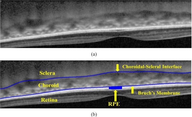
The high-contrast cross-sectional image of the choroid in vivo provided by SPECTRALIS® is shown in Fig. 2 (a). There are two ways to acquire the EDI-OCT using SPECTRALIS ®: One way is manually pushing the focal plane closer to the choroid and the inverted image of choroid and retina is captured; the other way is capturing the image using the built-in algorithm and the image is non-inverted. The latter type of EDI-OCT is flipped upside down as shown in Fig. 2 for the consistency in our analysis. As shown in Fig. 2 (b), the choroid is bounded by two structural interfaces, the choroidal-scleral interface (denoted as CCSI) and Bruch’s Membrane (denoted as CBM), which are manually labeled and the region in between is the choroid.
Fig. 2.
(a) EDI-OCT image in the macular region of the human eye. (b) The Bruch’s Membrane and the choroidal-scleral interface are manually labeled by the ophthalmologists.
An automatic algorithm that could detect the CCSI and CBM from EDI-OCT images is described in Section 2.1 to Section 2.3 and its schematic overview is shown in Fig. 3.
Fig. 3.

The overview of the automatic segmentation of the choroid in EDI-OCT images.
2.1. Preprocessing
To suppress additive thermal noise and electronic noise, the original EDI-OCT image denoted as I(x, y) for (x, y) ∈ [1, Nc] × [1, Nr] is first convolved with a 5 × 5 Wiener filter, which is adaptive to the estimated noise level. Then each point in the A-scan is replaced by an N-point moving average to reduce the spurious peaks caused by the speckle noise. The larger value of N will reduce the number of spurious peaks with the risk of wrong delineation of CSI. The image after denoising is denoted as Î(x, y).
2.2. BM detection and straightening
It is observed that the RPE is the brightest layer within the EDI-OCT image, so the pixels with the highest intensities in the A-scans is assigned as the ridge of RPE, which is denoted by CRPE and defined by
| (1) |
where fx(u) = Î(x,u) and it corresponds to the intensities of the denoised image Î in the column x. Bruch’s membrane, BM, defined by Eq. (2), is the upper boundary of the RPE and can be located by searching for the pixels with the largest gradient value above the CRPE
| (2) |
where g = [1 1 1 0 −1 −1 −1] is the gradient operator and Δ is the search range. Basically, the gradient operator g computes the difference between the sum of the neighboring pixels below and above the pixel (x,u) and the value is maximized at Bruch’s membrane location if we assume the intensities of pixels in the RPE layer is greater than the ones in the choroid. In order to form the smooth boundary, a 4th order polynomial fBM (x) = p̃4x4 + p̃3x3 + p̃2x2 + p̃1x + p̃0 is used to fit the points in BM and the smoothed Bruch’s membrane is denoted as CBM = {(x, fBM (x))}, where the coefficients are given by
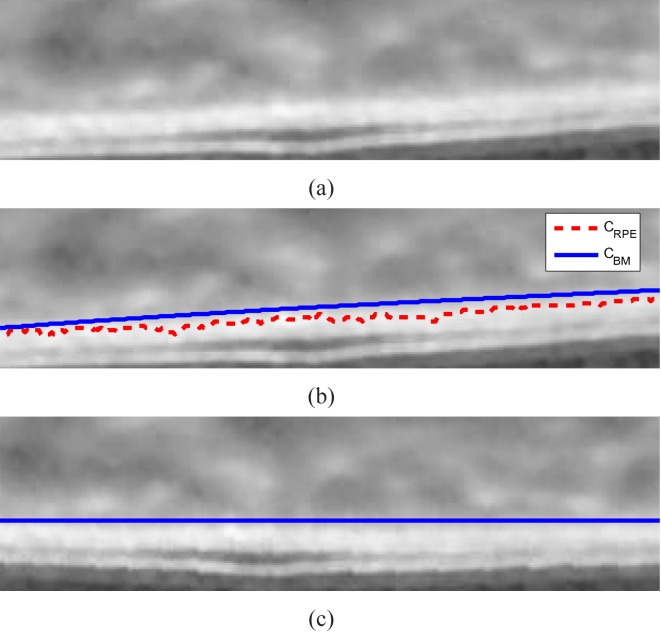
The result of the Bruch’s membrane detection is illustrated in Fig. 4 (b).
Fig. 4.
BM detection algorithm. (a) Part of the EDI-OCT image, (b) The detected RPE (CRPE in red dotted line) and Bruch’s membrane (CBM in blue solid line). (c) The new image Îs has the flat Bruch’s membrane.
Each A-scan of the OCT image is shifted up or down so that the Bruch’s membrane is straight in the new image Îs(x, y). The purpose of straightening step is to avoid inaccurate shortcuts across the choroid due to the natural retinal curvature in the EDI-OCT image when detecting the choroidal-scleral interface using graph search. The results of the straightened image is shown in Fig. 4 (c).
2.3. CSI detection
Choroidal-scleral interface (CCSI) is the boundary between the choroid and the sclera, which are two tissues with the different structures. The sclera contains collagen and elastic fibers and has rather uniform structure in the OCT images, while the choroid consists of collagen fibers, bibroblasts, melanocytes and other vasculatures and does not have homogeneous textures [25]. The changes between tissue structures create distinct valleys in the OCT A-scans and hence we can delineate CCSI as the smooth curve formed by “valley pixels”. In this paper, valley pixels are defined as the local minima of A-scans and are used as the feature to detect the choroidal-scleral interface. However, the valley pixels are also caused by the speckle noise and the blood vessels in the choroid as shown in Fig. 5. So how can we distinguish the valley pixels caused by CCSI from the ones caused by speckle noise and blood vessels?
Fig. 5.

The valleys (local minimums) of the A-scans are used as the feature to detect the choroidal-scleral interface. However, there are also valleys caused by the speckle noise and the blood vessels in the choroid region.
If we assume that the choroidal-scleral interface is a continuous and smooth curve, the valley pixels caused by it are close to one another and can be connected to form a smooth path between valley pixels on both ends of the image. On the other hand, the valley pixels caused by the speckle noise appears randomly located and the ones caused by blood vessels in the choroid region form short layer segments, which means that the smooth path can not be formed by these valley pixels as illustrated in Fig. 5.
Therefore, we devise a shortest path search to delineate the CCSI. First, valley pixels are detected as described in Section 2.3.1. Then every valley pixel is represented as a vertex of a directed graph G and each vertex is connected to the vertices in the next Nnh columns. The CCSI corresponds to the shortest path between the vertices on both ends. The construction of the graph and the end point initialization are presented in Section 2.3.2. Lastly, the proposed algorithm is compared with the generalized layer segmentation algorithm using graph search in [18] in Section 2.3.3 to highlight its advantage in the choroid segmentation.
2.3.1. Valley Pixels Detection
In this algorithm, the valley pixels of every 3 A-scans are detected as defined in Eq. (3)
| (3) |
where
The algorithm ValleyDet is to detect local minimums in 1-D as defined in Algorithm 1, is the average intensities of the pixels in column x −1, x and x + 1 of Îs, and δ is the variation threshold (the variations less than δ is ignored). The algorithm ValleyDet searches for the alternating valleys and peaks and is briefly explained as follows: The value of Lmax is either 1 or 0, which indicates whether to search for local maxima or minima in the current location u. We initialized the algorithm by setting Lmax = 0, umax = 1 and umin = 1, where umax denotes the location of previous peak and umin denotes the local minima in [umax, u]. If the current location u is δpixel higher than umin, the curve is increasing from a valley to a peak and hence, the current umin is included as a local valley pixel and then the local maxima is searched in the next step. The same process is repeated until all the valley pixels are found. Taking the average of three adjacent A-scans could reduce the noise effectively without much loss of information because the adjacent columns are very similar. By doing so, the number of vertices in the graph is greatly reduced and the processing speed is improved.
The detected valley pixels below the Bruch’s membrane are discarded and the results are illustrated in Fig. 5.
2.3.2. Graph construction
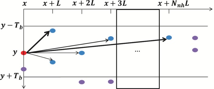
To construct a graph G = (V, E), each valley pixel is assigned as a vertex of G, VI ⊂ V. Every vertex is connected to the vertices in the next Nnh columns within the vertical range [−Tb, Tb] as illustrated in Fig. 6.
Fig. 6.
Construction of graph G, each valley pixel is a vertex of the graph and is connected to the vertices in the next Nnh columns.
Algorithm 1.
V = ValleyDet(g, δ)
| V = ∅ |
| Lmax = 0; umax = 1; umin = 1 |
| for u = 2 : Nr |
| if g(u) > g(umax), then umax = u end |
| if g(u) < g(umin), then umin = u end |
| if Lmax |
| if g(u) < g(umax) −δ, then umin = u, Lmax = 0 end |
| else |
| if g(u) > g(umin) +δ, V ← umin ∪ V, umax = u, Lmax = 1 end |
| end |
| end |
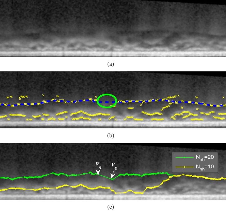
The threshold Tb is used to eliminate the abrupt transitions of the delineated boundary. The reason for connecting the vertex to the valley pixels in Nnh columns is to overcome the missing boundary problem as illustrated in Fig. 7. The choroidal-scleral interface is invisible in some locations (referred as gaps) as indicated in Fig. 7 (b). By letting the value of 3Nnh be greater than the largest horizontal size of the gaps, the valley pixels on both ends (vs and ve) can be directly connected and the graph search algorithm could find the correct boundary as shown in Fig. 7 (c). However, the algorithm would fail to delineate the right boundary if 3Nnh is less than the horizontal size of the gaps. The greater value of Nnh would improve the robustness of the algorithm but the processing time is also increased.
Fig. 7.
(a) A straighted EDI-OCT image. (b) The choroidal-scleral interface is sometimes invisible and the missing boundary is refereed as gaps (circles), where the valley pixels (cross) do not appear near the manual labeled choroidal-scleral interface (dashed lines). (c) The delineation result of the proposed algorithm by setting Nnh = 10 and Nnh = 20. When Nnh = 20, the value 3Nnh (60 pixels) is greater than the horizontal distance of the largest gap (57 pixels). Therefore, vs and ve is connected and the result agrees well with the manual labeling in (b);
Assigning the weight of each edge is a crucial component in the graph construction. In this algorithm, the weight of the edge between vertices a and b is assigned according to Eq. (4)
| (4) |
where Δx and Δy are the horizontal and vertical distance between a and b, respectively; H(·) is the heaviside function; the penalizing factor wM is a large constant; the value Tp is the threshold to define the closeness of the two vertices and edges having Δy ≥ Tp will be assigned additional large penalty weights; the value α controls the increase rate of penalty weight wp. The rational of the proposed weight assignment is illustrated in Fig. 8 and discussed as follows:
-
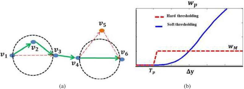
Figure 8 (a) gives an example illustrating the behavior of the shortest path search when the vertical distance between any two vertices are all less than Tp for the vertices {v1, v2, v3, v4, v5, v6}. According to Eq. (4), w(vi, vj) = ||vi − vj||2 for any i, j ∈ [1, 6]. As the angle between (v2 − v1) and (v3 − v2) is less than 90 degrees,
Therefore,
The shortest path of the graph should pass the intermediate vertex v2 if it is located within the circle that has v1 and v3 as the diameters.On the other hand, the shortest path of the graph prefer the direct path and ignore the intermediate vertex v5 as it is located outside the circle that has v4 and v6 as the diameters. These behaviors enable the shortest path search algorithm to include as many closely located vertices as possible and ignore the outliers.
- The weight wp, which is a large penalization term when Δy > Tp to ensure the smoothness of the delineated boundary, is plotted in Fig. 8 (b). The simplest way of designing wp is hard thresholding method as defined in Eq. (5),
However, the delineated results are sensitive to the value Tp and such weight assignment scheme depends on the proper selection of the threshold. To overcome this, a soft thresholding method as defined in Eq. (4) is proposed, where the a sigmoid function ( ) is used to smooth the transition near the boundary of Tp and the parameter α controls the smoothness of the transition. The value of the threshold Tp is less important and can be set to a fixed value without the need of adjustment.(5)
Fig. 8.
(a) Construction of graph G, each valley pixel is a vertex of the graph and is connected to the vertex in the next Nnh columns; (b) Hard and soft thresholding methods for assigning penalty weights.
After the construction of graph G, the choroidal-scleral interface in the straightened image can be found by searching for the shortest path of G between the vertices on both ends using Dijkstra’s algorithm [26]. However, when there are more than one vertices in the first and last columns, finding the shortest path requires the selection of starting and ending points. Here we propose an automatic end point initialization method to avoid the manual selection process.
Two virtual vertices are added to the graph and assigned as the first and last nodes. The first node is connected to the vertices in the first Nnh columns with the minimum edge weight of 1. Similarly, the last node is connected with the vertices in the last Nnh with the minimum edge weight of 1.
The vertices on the shortest path between the first and last nodes are transformed from the straightened image to the original image and then used as the key points to generate the final boundary CCSI using linear interpolation. The segmented choroid is the area between CBM and CCSI as defined in Eq. (6)
| (6) |
where (x, yCSI) ∈ CCSI, (x, yBM) ∈ CBM. The thickness of the choroid can be calculated as given in Eq. (7)
| (7) |
where σa is the axial resolution and |·| denotes the cardinality of a set.
2.3.3. Comparison with the generalized layer segmentation algorithm using dynamic programming
The CSI detection algorithm presented in Section. 2.3.2 has some similarities with the generalized layer segmentation algorithm using dynamic programming proposed in [18], i.e. graph search is used to track the layer boundaries and the same end point initialization method. The fundamental differences are highlighted next to explain the reason why our algorithm is more suitable for the choroidal-scleral interface delineation task:
Vertex assignment: We consider the valley pixels in every three A-scans as the vertices of the graph while in [18], every pixels in the image is considered. Our vertex assignment method reduces the number of vertices greatly based on the assumption that the layer boundaries is a smoothed curve formed by valley pixels, which is supported by OCT fundamental principles.
Graph connectivity: In our proposed algorithm, every vertex is connected to the vertices in the next Nnh columns to overcome the problem of invisible boundary (gaps). However, in [18], every vertex is only connected with its direct neighbor (4-neighborhood or 8-neighborhood).
Weight assignment: The weight of each edge is related to the spatial locations of the vertices as shown in Eq. (4). The edges with closely related vertices are assigned with small weights and the edges connecting vertices far apart are assigned large weights. On the other hand, the weight assignment in [18] mainly considered the gradients values, which is not suitable in the CCSI delineation, because the gradient of the choroidal-scleral interface is sometimes weaker than the valley pixels caused by blood vessels.
3. Experiments and results
To evaluate the performance of the proposed segmentation algorithm, experiments are conducted on 45 EDI-OCT images from 45 subjects captured by SPECTRALIS® system with software version 5.3 at the Singapore Eye Research Institute. To simplify the process of manual labelings, only one image that passes through the center of the fovea is selected to conduct the experiments. Twenty-five of these images are acquired by manual pushing and the other 20 images are from the built-in software with EDI-OCT function.
The images are labeled as In, n = 1, 2 ...45 and the pixel resolutions are 3.9μm/pixel in axial direction and 14μm/pixel in transversal direction. The scan depth and field of view are 1.9 mm and 30°, respectively. In order to reduce the speckle noise and have better contrast, all the images are captured with Automatic Real Time (ART) Mean mode, which generates each B-scan from the time averaged NART frames at the specific scan position.
The algorithm is implemented in Matlab R2011a using an Intel® Core™ i5-2400 @3.1GHz and 3.1GHz 64 bits computer and the parameter settings are summarized in Table 1. A Matlab graphic user interface is designed to assist the experiments of manual labelings, which were used as the ground truth to evaluate the accuracy of the proposed algorithm. In the manual labeling experiments, the positions of the Bruch’s membrane at discrete locations (5 to 10 locations) are indicated by the ophthalmologist and the labeled points are interpolated using cubic spline to approximate the layer corresponding to the Bruch’s membrane . Our manual labeling experiments are similar to the labeling process in the built-in software of SPECTRALIS ®. The same process is repeated to get . The manual labeled choroid region CHT0 is the area between and and the ground truth of choroidal thickness is denoted as fCHT0 (x).
Table 1.
The parameter settings in the experiments
| Parameters Value | Brief Description of the Parameters |
|---|---|
| N=5 | The number of points used to smooth each A-scan |
| Nc=1536 | The number of columns in EDI-OCT images |
| Nr=487 | The number of rows in EDI-OCT images |
| Δ=20 | The search range in Bruch’s membrane detection |
| δ =3 | The variation threshold in the valley pixel detection |
| Tb=30 | The vertical range of vertex connectivity |
| Nnh=25 | The number of columns a vertex would connect to |
| Tp=5 | The threshold of closeness |
| α=2 | The constant controlling the increase rate of wp |
| wM =20, 000 | The constant used to penalize large vertical displacement |
| NART =25 | The number of frames used in ART |
Two performance metrics are defined to measure the accuracy of the proposed choroid segmentation algorithm:
- Dice’s coefficient is used to evaluate the similarity between segmentation results of the algorithm and the ground truth and it as defined in
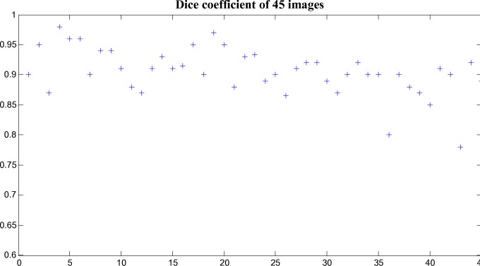
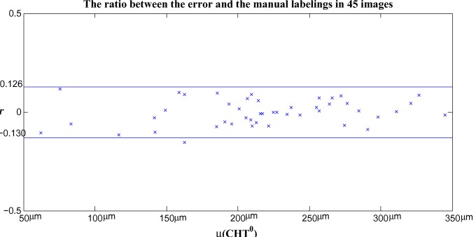
The values of Dice’s coefficient in 45 images are plotted in Fig. 9. - The ratio r is defined to quantify the accuracy of the algorithm in measuring the choroidal thickness and it is given as follows
The ratio r versus the average choroidal thickness in 45 images are plotted in Fig. 10.
Fig. 9.
The Dice’s coefficient of the choroid segmentation between the output of the proposed algorithm and the manual labelings.
Fig. 10.
The ratio between the error and the manual labelings in estimating the choroidal thickness of 45 EDI-OCT images.
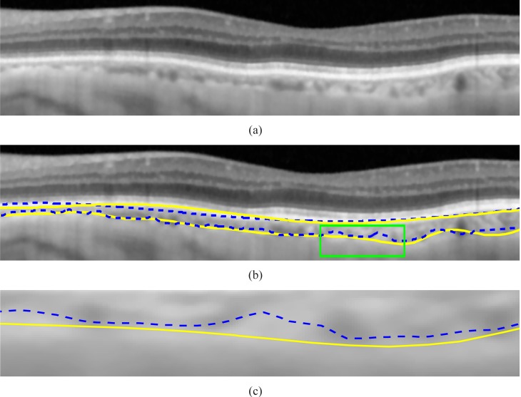
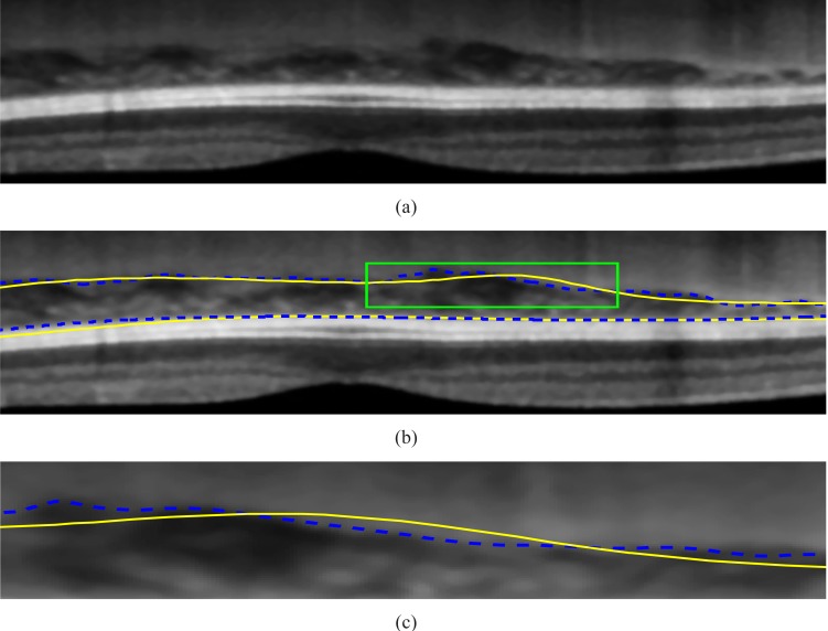
It is found that the average of the Dice’s coefficients over 45 tested images is 90.5% with the standard deviation of 3%, which shows the good consistency between the manual labelings and our algorithm. The delineation results in the non-inverted image I43 and inverted image I6 are shown in Fig. 11 and Fig. 12, respectively.
Fig. 11.
(a) A part of non-inverted image I43. (b) The comparison between the results of the proposed algorithm(indicated by the dash lines) and the ground truth labeled by the ophthalmologists (drawn in solid lines). (c) The enlarged major discrepancy region.
Fig. 12.
(a) A part of the inverted image I6. (b) The comparison between the results of the proposed algorithm(indicated by the dash lines) and the ground truth labeled by the ophthalmologists (drawn in solid lines). (c)The enlarged major discrepancy region.
It can be observed that the delineation results are generally consistent with the manual labellings. The discrepancy is because the algorithm follows the valley pixels more closely while the manual labelings are smoother due to the limited number of input data points. The larger errors in the outliers, I43 and I36, are due to the thinner CHT regions, i.e. the mean choroidal thickness of image I43 and I36 are 29 and 31 pixels, respectively, while the mean choroidal thickness is 70 pixels in image I6. Because when the choroid is thinner, the ratio between the error and CHT0 is larger for the same amount of discrepancy. For instance, an image with the CHT errors of 5 pixels and average choroidal thickness of 100 pixels has Dice’s coefficient of 95%. However, the Dice’s coefficient will drop to 88% for the same amount of error (5 pixels) when the average choroidal thickness is 60 pixels. Hence, the Dice’s coefficient is smaller for the thinner choroid. It is noteworthy that the manually marked choroidal-scleral interface is smoother as compared to automated solution. Because the small curvature changes on the choroidal-scleral interface requires the ophthalmologists to mark additional points and it is often not visible unless every part of the image is zoomed into a large window during the labeling process. Automated segmentation takes into account small bumps and crevices in the interface and smoothening of the interface line is done in a more controlled manner. The differences between manual and an automatic solution is in a few pixels and generally they correlate well.
The average and standard deviation of r for 45 images are −0.2% and 6.5%, respectively. If we assume r having a Gaussian distribution, 95% confidence interval is [−0.13, 0.126].
The processing speed of the proposed algorithm is very fast and real time segmentation is possible. The average processing time is 1.25 seconds/image.
4. Conclusion and Future Work
In this paper, a fast and accurate algorithm that could segment the choroid in EDI-OCT images is presented. The comparative studies between output of the proposed algorithm and the manual labelings are conducted on 45 images and a good consistency of 90.5% is observed. The processing time is about 1 second, which is suitable for conducting the clinical studies.
The choroidal-scleral interface is delineated by finding the shortest path of the graph constructed from valley pixels based on the assumption that the choroidal-scleral interface is a smooth curve formed by valley pixels, which is supported by the OCT principles. Hence, the proposed algorithm should be robust in segmentation of the choroid regardless the imaging modality, i.e. the polarization sensitive optical coherence tomography (PS-OCT) and high penetration optical coherence tomography (HP-OCT). As a future work, more experiments need to be conducted to prove the robustness of the algorithm on OCT images from different imaging modalities. Furthermore, 3D choroidal thickness map could also be studied with the use of the proposed algorithm. The ultimate goal is developing a standalone software for measuring the choroid thickness so as to assist the clinicians in conducting research and make diagnosis. In addition, a more generalized layer detection algorithm could be developed to target other OCT image segmentation problems, i.e. anterior segment OCT [27].
Acknowledgment
The images used in this study are obtained as a part of the clinical research project supported by the National Medical Research Council, Singapore.
References and links
- 1.Margolis R., Spaide R. F., “A pilot study of enhanced depth imaging optical coherence tomography of the choroid in normal eyes,” Am. J. Ophthalmol. 147, 811–815 (2009). 10.1016/j.ajo.2008.12.008 [DOI] [PubMed] [Google Scholar]
- 2.Quigley H. A., “What’s the choroid got to do with angle closure?” Arch. Ophthalmol. 127(5), 693–4 (2009). 10.1001/archophthalmol.2009.80 [DOI] [PubMed] [Google Scholar]
- 3.Ikuno Y., Kawaguchi K., Nouchi T., Yasuno Y., “Choroidal thickness in healthy Japanese subjects,” Invest. Ophthalmol. Vis. Sci. 51, 2173–2176 (2010). 10.1167/iovs.09-4383 [DOI] [PubMed] [Google Scholar]
- 4.Ding X., Li J., Zeng J., Ma W., Liu R., Li T., Yu S., Tang S., “Choroidal thickness in healthy Chinese subjects,” Invest. Ophthalmol. Vis. Sci. 52, 9555–9560 (2011). 10.1167/iovs.11-8076 [DOI] [PubMed] [Google Scholar]
- 5.Manjunath V., Taha M., Fujimoto J. G., Duker J. S., “Choroidal thickness in normal eyes measured using Cirrus HD optical coherence tomography,” Am. J. Ophthalmol. 150, 325–329 (2010). 10.1016/j.ajo.2010.04.018 [DOI] [PMC free article] [PubMed] [Google Scholar]
- 6.Nickla D. L., Wildsoet C., Wallman J., “The circadian rhythm in intraocular pressure and its relation to diurnal ocular growth changes in chicks,” Exp. Eye. Res. 66, 183–193 (1998). 10.1006/exer.1997.0425 [DOI] [PubMed] [Google Scholar]
- 7.Huang D., Swanson E. A., Lin C. P., Schuman J. S., Stinson W. G., Chang W., Hee M. R., Flotte T., Gregory K., Puliafito C. A., “Optical coherence tomography,” Science 254, 1178–1181 (1991). 10.1126/science.1957169 [DOI] [PMC free article] [PubMed] [Google Scholar]
- 8.Wang R. K., “Signal degradation by multiple scattering in optical coherence tomography of dense tissue: a monte carlo study towards optical clearing of biotissues,” Phys. Med. Biol. 47, 2281–2299 (2002). 10.1088/0031-9155/47/13/307 [DOI] [PubMed] [Google Scholar]
- 9.Spaide R. F., Koizumi H., Pozzoni M. C., Pozonni M. C., “Enhanced depth imaging spectral-domain optical coherence tomography,” Am. J. Ophthalmol. 146, 496–500 (2008). 10.1016/j.ajo.2008.05.032 [DOI] [PubMed] [Google Scholar]
- 10.Chung S. E., Kang S. W., Lee J. H., Kim Y. T., “Choroidal thickness in polypoidal choroidal vasculopathy and exudative age-related macular degeneration,” Ophthalmology 118, 840–845 (2011). 10.1016/j.ophtha.2010.09.012 [DOI] [PubMed] [Google Scholar]
- 11.Fong A. H. C., Li K. K. W., Wong D., “Choroidal evaluation using enhanced depth imaging spectral-domain optical coherence tomography in Vogt-Koyanagi-Harada disease,” Retina 31, 502–509 (2011). 10.1097/IAE.0b013e3182083beb [DOI] [PubMed] [Google Scholar]
- 12.Maruko I., Iida T., Sugano Y., Ojima A., Sekiryu T., “Subfoveal choroidal thickness in fellow eyes of patients with central serous chorioretinopathy,” Retina 31, 1603–1608 (2011). 10.1097/IAE.0b013e31820f4b39 [DOI] [PubMed] [Google Scholar]
- 13.Mwanza J.-C., Hochberg J. T., Banitt M. R., Feuer W. J., Budenz D. L., “Lack of association between glaucoma and macular choroidal thickness measured with enhanced depth-imaging optical coherence tomography,” Invest. Ophthalmol. Vis Sci. 52, 3430–3435 (2011). 10.1167/iovs.10-6600 [DOI] [PMC free article] [PubMed] [Google Scholar]
- 14.Maruko I., Iida T., Sugano Y., Ojima A., Ogasawara M., Spaide R. F., “Subfoveal choroidal thickness after treatment of central serous chorioretinopathy,” Ophthalmology 117, 1792–1799 (2010). 10.1016/j.ophtha.2010.01.023 [DOI] [PubMed] [Google Scholar]
- 15.Maruko I., Iida T., Sugano Y., Oyamada H., Sekiryu T., Fujiwara T., Spaide R. F., “Subfoveal choroidal thickness after treatment of Vogt-Koyanagi-Harada disease,” Retina 31, 510–517 (2011). 10.1097/IAE.0b013e3181eef053 [DOI] [PubMed] [Google Scholar]
- 16.Yazdanpanah A., Hamar G., “Segmentation of intra-retinal layers from optical coherence tomgraphy images using an active contour approach,” IEEE Trans. Med. Imaging 30, 484–496 (2011). 10.1109/TMI.2010.2087390 [DOI] [PubMed] [Google Scholar]
- 17.Garvin M. K., Abramoff M. D., Kardon R., Russell S. R., Wu X., Sonka M., “Intraretinal layer segmentation of macular optical coherence tomography images using optimal 3-D graph search,” IEEE Trans. Med. Imaging 27, 1495–1505 (2008). 10.1109/TMI.2008.923966 [DOI] [PMC free article] [PubMed] [Google Scholar]
- 18.Chiu S. J., Li X. T., Nicholas P., Toth C. A., Izatt J. A., Farsiu S., “Automatic segmentation of seven retinal layers in SD-OCT images congruent with expert manual segmentation,” Opt. Express 18, 19413–19428 (2010). 10.1364/OE.18.019413 [DOI] [PMC free article] [PubMed] [Google Scholar]
- 19.Yang Q., Reisman C. A., Wang Z., Fukuma Y., Hangai M., Yoshimura N., Tomidokoro A., Araie M., Raza A. S., Hood D. C., Chan K., “Automated layer segmentation of macular OCT images using dual-scale gradient information.” Opt. Express 18, 21293–21307 (2010). 10.1364/OE.18.021293 [DOI] [PMC free article] [PubMed] [Google Scholar]
- 20.Koozekanani D., Boyer K., Roberts C., “Retinal thickness measurements from optical coherence tomgraphy using a Markov boundary model,” IEEE Trans. Med. Imaging 20, 906–916 (2001). 10.1109/42.952728 [DOI] [PubMed] [Google Scholar]
- 21.Zhang L., Lee K., Niemeijer M., Mullins R. F., Sonka M., Abramoff M. D., “Automated segmentation of the choroid from clinical SD-OCT,” Invest. Ophthalmol. Vis. Sci. 53, 7510–7519 (2012). 10.1167/iovs.12-10311 [DOI] [PMC free article] [PubMed] [Google Scholar]
- 22.Kajic V., Esmaeelpour M., Povazay B., Marshall D., Rosin P. L., Drexler W., “Automated choroidal segmentation of 1060 nm OCT in healthy and pathologic eyes using a statistical mode,” Biomed. Opt. Express 3, 86–103 (2012). 10.1364/BOE.3.000086 [DOI] [PMC free article] [PubMed] [Google Scholar]
- 23.Torzicky T., Pircher M., Zotter S., Bonesi M., Gotzinger E., Hitzenberger C. K., “Automated measurement of choroidal thickness in the human eye by polarization sensitive optical coherence tomography,” Opt. Express 20, 7564–7574 (2012). 10.1364/OE.20.007564 [DOI] [PMC free article] [PubMed] [Google Scholar]
- 24.Duan L., Yamanari M., Yasuno Y., “Automated phase retardation oriented segmentation of chorio-scleral interface by polarization sensitive optical coherence tomography,” Opt. Express 20, 3353–3366 (2012). 10.1364/OE.20.003353 [DOI] [PubMed] [Google Scholar]
- 25.Nickla D., Wallman J., “The multifunctional choroid,” Prog. Retinal Res. 29, 144–168 (2010). 10.1016/j.preteyeres.2009.12.002 [DOI] [PMC free article] [PubMed] [Google Scholar]
- 26.Dijkstra E. W., “A note on two problems in connexion with graphs,” Numerische Math. 1, 269–271 (1959). 10.1007/BF01386390 [DOI] [Google Scholar]
- 27.Tian J., Marziliano P., “Location-based graph search algorithm for boundary detection in oct images,” to be submitted to IEEE Trans. Med. Imaging.


