Abstract
Ice-binding proteins (IBPs), including antifreeze proteins, ice structuring proteins, thermal hysteresis proteins, and ice recrystallization inhibition proteins, are found in cold-adapted organisms and protect them from freeze injuries by interacting with ice crystals. IBPs are found in a variety of organism, including fish1, plants2, 3, arthropods4, 5, fungi6, and bacteria7. IBPs adsorb to the surfaces of ice crystals and prevent water molecules from joining the ice lattice at the IBP adsorption location. Ice that grows on the crystal surface between the adsorbed IBPs develops a high curvature that lowers the temperature at which the ice crystals grow, a phenomenon referred to as the Gibbs-Thomson effect. This depression creates a gap (thermal hysteresis, TH) between the melting point and the nonequilibrium freezing point, within which ice growth is arrested8-10, see Figure 1. One of the main tools used in IBP research is the nanoliter osmometer, which facilitates measurements of the TH activities of IBP solutions. Nanoliter osmometers, such as the Clifton instrument (Clifton Technical Physics, Hartford, NY,) and Otago instrument (Otago Osmometers, Dunedin, New Zealand), were designed to measure the osmolarity of a solution by measuring the melting point depression of droplets with nanoliter volumes. These devices were used to measure the osmolarities of biological samples, such as tears11, and were found to be useful in IBP research. Manual control over these nanoliter osmometers limited the experimental possibilities. Temperature rate changes could not be controlled reliably, the temperature range of the Clifton instrument was limited to 4,000 mOsmol (about -7.5 °C), and temperature recordings as a function of time were not an available option for these instruments.
We designed a custom-made computer-controlled nanoliter osmometer system using a LabVIEW platform (National Instruments). The cold stage, described previously9, 10, contains a metal block through which water circulates, thereby functioning as a heat sink, see Figure 2. Attached to this block are thermoelectric coolers that may be driven using a commercial temperature controller that can be controlled via LabVIEW modules, see Figure 3. Further details are provided below. The major advantage of this system is its sensitive temperature control, see Figure 4. Automated temperature control permits the coordination of a fixed temperature ramp with a video microscopy output containing additional experimental details.
To study the time dependence of the TH activity, we tested a 58 kDa hyperactive IBP from the Antarctic bacterium Marinomonas primoryensis (MpIBP)12. This protein was tagged with enhanced green fluorescence proteins (eGFP) in a construct developed by Peter Davies' group (Queens University)10. We showed that the temperature change profile affected the TH activity. Excellent control over the temperature profile in these experiments significantly improved the TH measurements. The nanoliter osmometer additionally allowed us to test the recrystallization inhibition of IBPs5, 13. In general, recrystallization is a phenomenon in which large crystals grow larger at the expense of small crystals. IBPs efficiently inhibit recrystallization, even at low concentrations14, 15. We used our LabVIEW-controlled osmometer to quantitatively follow the recrystallization of ice and to enforce a constant ice fraction using simultaneous real-time video analysis of the images and temperature feedback from the sample chamber13. The real-time calculations offer additional control options during an experimental procedure. A stage for an inverted microscope was developed to accommodate temperature-controlled microfluidic devices, which will be described elsewhere16.
The Cold Stage System
The cold stage assembly (Figure 2) consists of a set of thermoelectric coolers that cool a copper plate. Heat is removed from the stage by flowing cold water through a closed compartment under the thermoelectric coolers. A 4 mm diameter hole in the middle of the copper plate serves as a viewing window. A 1 mm diameter in-plane hole was drilled to fit the thermistor. A custom-made copper disc (7 mm in diameter) with several holes (500 μm in diameter) was placed on the copper plate and aligned with the viewing window. Air was pumped at a flow rate of 35 ml/sec and dried using Drierite (W.A. Hammond). The dry air was used to ensure a dry environment at the cooling stage. The stage was connected via a 9 pin connection outlet to a temperature controller (Model 3040 or 3150, Newport Corporation, Irvine, California, US). The temperature controller was connected via a cable to a computer GPIB-PCI card (National instruments, Austin, Texas, USA).
Keywords: Biochemistry, Issue 72, Chemistry, Physics, Biophysics, Bioengineering, Microbiology, Proteins, Ice binding proteins, IBP, antifreeze proteins, thermal hysteresis proteins, TH, ice structuring proteins, recrystallization inhibition proteins, nanoliter osmometer, LabVIEW, temperature control, microscopy stage, nano, Gibbs-Thomson effect, microfluidics, microscale chemistry
Protocol
0. Preliminary Procedures
Glass capillary for solution injection. Using a capillary puller (Narishige, Tokyo, Japan), prepare a sharp pipette with a fine opening from a glass capillary micro tube (Brand GMBH, Wertheim, Germany). The size of the opening should be verified by passing air through the capillary to obtain fine bubbling in clean water. If the capillary is closed, then one may open it by breaking its edge. This may be accomplished by pressing or scratching it gently against the water containing tube walls. Prepare the capillary such that the opening is nearly blocked but is sufficiently open to allow the formation of sub-millimeter bubbles.
Copper disc cleaning. Sonicate the copper discs for 10 min in 0.1% Micro-90 soap (Cole-Parmer, Vernon Hills, Illinois, USA), then wash with double distilled water. Introduce the discs into an isopropanol (technical) solution and sonicate again for 10 min. Finally, dry the discs using filtered air. This cleaning stage is critical to avoid IBP contamination between experiments.
Double-layer coverglass assembly. A coverglass assembly was prepared to allow for sample observation without condensing moisture on the cover glass surface. This was achieved by placing a Drierite (W.A. Hammond Drierite, Xenia, Ohio, USA) particle (2 mm in diameter) between two coverslips that were then glued with a hot glue gun. This configuration prevented condensation that could block the view when the sample was cooled to low temperatures and removed the need to blow dry air onto the observation window.
1. Cooling Stage Set-up
Connect the water flow inlet and outlet of the cooling stage to 4 mm inner diameter Tygon tubes (Saint-Gobain, Paris, France), and connect the water flow inlet tube to a water pump.
Connect a 4 mm inner diameter Tygon tube to the inlet of the cooling stage to deliver dry air. The air was dried using an in-line Drierite column.
Operate the air and water pumps. Note that the cooling elements should not be run without a heat sink.
Turn on the temperature controller, camera, and LabVIEW routine.
2. Sample Preparation
Place a 3-4 μl droplet of immersion oil B (Cargille laboratories, Cedar Grove, New Jersey, USA) on the back side of a 7 mm diameter copper disc having 500 μm holes drilled through the disc.
Position the copper disc on the cooling stage with the immersion oil side facing down.
Connect the capillary tube (the blunt edge) to a 0.7 mm inner diameter Tygon tube connected at the other end to a 2 ml glass syringe (Poulten-Graf, Wertheim, Germany).
Prior to using the capillary tube, check the small opening of the capillary to ensure that the opening is an appropriate size (see the Preliminary procedures).
Slowly insert the glass capillary into the prepared IBP protein sample tube (2.4 μM MpIBP-GFP in 20 mM CaCl2 and 25 mM Tris-HCl at pH 8, see reference10 for the preparation details) and pull the glass syringe until the glass capillary contains 0.1 μl of the protein solution.
Begin video recording via the LabVIEW software.
Insert the sharp edge of the glass capillary (containing the protein solution) into one of the holes in the copper disc on the cooling stage.
While observing through the microscope (Olympus, Tokyo, Japan, 10x objective), carefully penetrate the immersion oil layer with the glass capillary tip, and press the glass syringe (very delicately) to deliver a small amount (~10 nl) of the protein solution to create a 200 μm droplet.
Cover the hole in the cooling stage with the double layer coverglass assembly (see the Preliminary Procedures).
3. TH Activity Measurement
Press the cooling button and set the temperature to -40 °C.
Initially, the solution droplet will be clear. At low temperatures, typically in the range -30 °C to -35 °C, the droplet changes color, indicating that the solution has been frozen. Immediately after the sample has frozen, increase the temperature slowly until the bulk ice begins to melt. A gradual increase of the temperature is necessary to avoid overshooting of the temperature that could result in the complete melting of the sample.
Switch to a 50x objective and begin to melt the ice by adjusting the temperature. This adjustment is interactive, and the final steps are typically performed using small temperature steps of 0.002 °C. Continue to melt until a single crystal remains. The final size of the crystal should be around 10 μm. The highest temperature at which melting has ceased is determined to be the melting point and is determined accurately in the later video analysis stage.
Set the temperature to a few hundredths of a Celsius degree below the melting point of the crystal and begin a temperature ramp with a 10 min delay. Adjust the ramping rate as desired. During this time, the crystal will be exposed to the IBPs.
Upon completion of the 10 min exposure time, the temperature will decrease automatically under the control of the LabVIEW routine.
Observe the crystal shape as the temperature decreases. At some point, the sudden burst of the ice crystal may be observed. The temperature at which this occurs is noted as the crystal burst temperature.
Use video analysis to determine the accurate melting point and the burst temperature. First, by using video analysis, find the accurate melting point. Recall that the highest temperature at which melting has ceased is determined to be the melting point. Document this melting point in a spreadsheet program. Then, determine the accurate crystal burst temperature, and document this value as well. The difference between the melting point and the freezing point, or crystal burst temperature, is the thermal hysteresis activity of the IBP solution.
4. Measurement of the Time-dependent TH Activity
Follow the protocol described in Sections 3.1-3.3 to prepare a single crystal of ice.
After formation of the crystal, set the delay time of the ramp as desired, and turn on the ramp.
The temperature will decrease at a fixed rate (according to the operators' requirements) automatically once the ramp delay time has passed.
Document the temperature at which the crystal burst occurs. Calculate the exposure time (the time between crystal formation and the crystal burst).
Repeat the experiment for various delay times and plot the TH activity as a function of the exposure time to evaluate the time-dependence of the TH activity.
Representative Results
Measurement of the TH time dependence
The LabVIEW-operated nanoliter osmometer facilitates the performance of accurate TH activity measurements. The constant temperature reduction rate permitted the measurement of the TH time dependence. The precise temperature control enabled by the nanoliter osmometer was crucial for these experiments. The exposure time of an ice crystal to the IBPs in solution is defined as the time period from the formation of the crystal (the end of the melting process) until the sudden growth of ice around the crystal (crystal burst). We found that the exposure time of the ice crystals to the IBPs crucially affected the TH activity. Short periods of IBP exposure (a few seconds) produced a low TH activity in the MpIBP-GFP solution (2.4 μM) (Figure 5). The TH activity increased with IBP exposure time until it reached a plateau at 4 min IBP exposure. At higher IBP concentrations, the plateau was reached at shorter times.
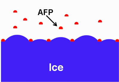 Figure 1. Schematic diagram illustrating IBPs adsorbed to ice. Adopted with permission from 10.
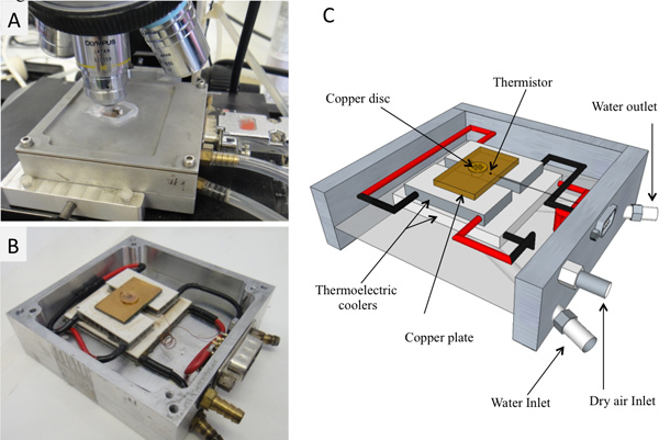 Figure 2. The cooling stage. A) Connected to tubes on the microscope. B) Without the upper lead. C) Schematic diagram. http://www.jove.com/files/ftp_upload/4189/4189fig2large.jpg
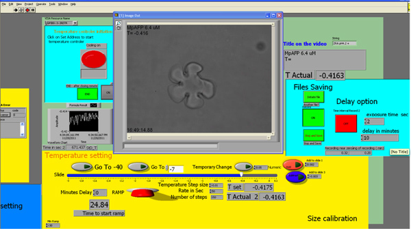 Figure 3. Screenshot of the LabVIEW interface. Click here to view larger figure.
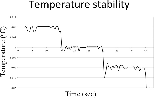 Figure 4. Temperature stability graph. The temperature controller was set to lower the temperature 0.01 °C every 15 sec.
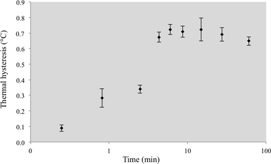 Figure 5.MpIBP TH activity as a function of ice crystal exposure time to the IBPs. Each time point is the average of 3-6 experiments.
Discussion
This work demonstrates the operation of a computer-controlled nanoliter osmometer that enables accurate measurements of TH activity with extraordinary temperature control. In any temperature-sensitive system, unwanted temperature gradients must be avoided. To avoid temperature gradients in the apparatus presented here, the test solution droplet must be positioned in the center of a hole in the copper disc cooling stage (step 2.7). Additionally, the single crystal should be in the center of the droplet rather than near the edges (in most cases, this will happen spontaneously). The time dependence described indicates that the cooling rate may influence the TH readings. Thus, we suggest including a report of the time during which the crystal was exposed to the solution prior to cooling, as well as the cooling rate. We typically waited 10 min prior to ramping down the temperature at 0.01 °C steps each 4 sec.
The LabVIEW-controlled cooling stage was adapted for use with an inverted microscope on which microfluidic devices could be thermally manipulated. This system facilitates the performance of solution exchange experiments involving ice crystals and IBPs tagged with eGFP9, 10, 16. The LabVIEW-controlled system may be adapted to a Clifton stage by connecting the 3,040 temperature controller via a designated adapting electric circuit. Such a system is operated in the Davies lab17. The LabVIEW software and the designated adapting electric circuit design for the Clifton stage are available upon request.
In conclusion, we describe a nanoliter osmometer that facilitates the sensitive control and manipulation of temperature and the rate of temperature increase and decrease (with 0.002 °C sensitivity), coordinated with a video interface through a LabVIEW routine for real-time analysis. This system can perform reproducible rate-controlled experiments that are important for investigating the kinetics of IBP interactions with ice. Such experiments can address several long-debated issues surrounding the mechanism of action of IBPs.
Disclosures
No conflicts of interest declared.
Acknowledgments
This research was supported by the ISF, NSF, and ERC. We would like to acknowledge technical help with the temperature stage from Randy Milford, Michael Koren, Doug Shafer, and Jeremy Dennison. Assistance with software development was provided by Or Chen, Di Xu, Rajesh Sannareddy, and Sumit Bhattachary. We would like to thank our collaborators Prof. Peter L. Davies and Dr. Laurie A. Graham for the MpIBP protein and helpful discussions. We also thank lab members Dr. Maya Bar-Dolev, Yangzhong Qin, Dr. Yeliz Celik, Dr. Natalya Pertaya, Ortal Mizrahy, and Shlomit Guy for their user feedback.
References
- DeVries AL. Glycoproteins as biological antifreeze agents in antarctic fishes. Science. 1971;172:1152–1155. doi: 10.1126/science.172.3988.1152. [DOI] [PubMed] [Google Scholar]
- Worrall D, Elias L, Ashford D, Smallwood M, Sidebottom C, Lillford P, Telford J, Holt C, Bowles D. A carrot leucine-rich-repeat protein that inhibits ice recrystallization. Science. 1998;282:115–117. doi: 10.1126/science.282.5386.115. [DOI] [PubMed] [Google Scholar]
- Raymond JA, Knight CA. Ice binding, recrystallization inhibition, and cryoprotective properties of ice-active substances associated with Antarctic sea ice diatoms. Cryobiology. 2003;46:174–181. doi: 10.1016/s0011-2240(03)00023-3. [DOI] [PubMed] [Google Scholar]
- Tomchaney AP, Morris JP, Kang SH, Duman JG. Purification, composition, and physical properties of a thermal hysteresis "antifreeze" protein from larvae of the beetle, Tenebrio molitor. Biochemistry. 1982;21:716–721. doi: 10.1021/bi00533a020. [DOI] [PubMed] [Google Scholar]
- Kiko R. Acquisition of freeze protection in a sea-ice crustacean through horizontal gene transfer. Polar Biology. 2010;33:543–556. [Google Scholar]
- Robinson CH. Cold adaptation in Arctic and Antarctic fungi. New Phytol. 2001;151:341–353. [Google Scholar]
- Gilbert JA, Hill PJ, Dodd CE, Laybourn-Parry J. Demonstration of antifreeze protein activity in Antarctic lake bacteria. Microbiology. 2004;150:171–180. doi: 10.1099/mic.0.26610-0. [DOI] [PubMed] [Google Scholar]
- Raymond JA, DeVries AL. Adsorption inhibition as a mechanism of freezing resistance in polar fishes. Proc. Natl. Acad. Sci. U.S.A. 1977;74:2589–2593. doi: 10.1073/pnas.74.6.2589. [DOI] [PMC free article] [PubMed] [Google Scholar]
- Pertaya N, Marshall CB, DiPrinzio CL, Wilen L, Thomson ES, Wettlaufer JS, Davies PL, Braslavsky I. Fluorescence microscopy evidence for quasi-permanent attachment of antifreeze proteins to ice surfaces. Biophys. J. 2007;92:3663–3673. doi: 10.1529/biophysj.106.096297. [DOI] [PMC free article] [PubMed] [Google Scholar]
- Celik Y, Graham LA, Mok YF, Bar M, Davies PL, Braslavsky I. Superheating of ice crystals in antifreeze protein solutions. Proc. Natl. Acad. Sci. U.S.A. 2010;107:5423–5428. doi: 10.1073/pnas.0909456107. [DOI] [PMC free article] [PubMed] [Google Scholar]
- Gilbard JP, Farris RL, Santamaria J. Osmolarity of tear microvolumes in keratoconjunctivitis sicca. Arch. Ophthalmol. 1978;96:677–681. doi: 10.1001/archopht.1978.03910050373015. [DOI] [PubMed] [Google Scholar]
- Gilbert JA, Davies PL, Laybourn-Parry J. A hyperactive, Ca2+-dependent antifreeze protein in an Antarctic bacterium. FEMS Microbiol. Lett. 2005;245:67–72. doi: 10.1016/j.femsle.2005.02.022. [DOI] [PubMed] [Google Scholar]
- Soriano J, Braslavsky I, Xu D, Krichevsky O, Stavans J. Universality of persistence exponents in two-dimensional ostwald ripening. Phys. Rev. Lett. 2009;103 doi: 10.1103/PhysRevLett.103.226101. [DOI] [PubMed] [Google Scholar]
- Tomczak MM, Marshall CB, Gilbert JA, Davies PL. A facile method for determining ice recrystallization inhibition by antifreeze proteins. Biochem. Bioph. Res. Co. 2003;311:1041–1046. doi: 10.1016/j.bbrc.2003.10.106. [DOI] [PubMed] [Google Scholar]
- Knight CA, Hallett J, Devries AL. Solute Effects on Ice Recrystallization - an Assessment Technique. Cryobiology. 1988;25:55–60. doi: 10.1016/0011-2240(88)90020-x. [DOI] [PubMed] [Google Scholar]
- Celik Y, Drori R, Pertaya-Braun N, Altan A, Barton T, Bar-Dolev M, Groisman A, Davies PL, Braslavsky I. Microfluidic experiments reveal that antifreeze proteins bound to ice crystals suffice to prevent their growth. Proc. Natl. Acad. Sci. U.S.A. 2013;110:1309–1314. doi: 10.1073/pnas.1213603110. [DOI] [PMC free article] [PubMed] [Google Scholar]
- Middleton AJ, Marshall CB, Faucher F, Bar-Dolev M, Braslavsky I, Campbell RL, Walker VK, Davies PL. Antifreeze protein from freeze-tolerant grass has a beta-roll fold with an irregularly structured ice-binding site. J. Mol. Biol. 2012;416:713–724. doi: 10.1016/j.jmb.2012.01.032. [DOI] [PubMed] [Google Scholar]


