

Abstract
Purpose: The prepatient attenuator (or “bowtie filter”) in CT is used to modulate the flux as a function of fan angle of the x-ray beam incident on the patient. Traditional, static bowtie filters are tailored only for very generic scans and for the average patient. The authors propose a design for a dynamic bowtie that can produce a time-dependent piecewise-linear attenuation profile. This dynamic bowtie may reduce dynamic range, dose or scatter, but in this work they focus on its ability to reduce dynamic range, which may be particularly important for systems employing photon-counting detectors.
Methods: The dynamic bowtie is composed of a set of triangular wedges. Each wedge is independently moved in order to produce a time-dependent piecewise-linear attenuation profile. Simulations of the bowtie are conducted to estimate the dynamic range reduction in six clinical datasets. The control of the dynamic bowtie is determined by solving a convex optimization problem, and the dose is estimated using Monte Carlo techniques. Beam hardening artifacts are also simulated.
Results: The dynamic range is reduced by factors ranging from 2.4 to 27 depending on the part of the body studied. With a dynamic range minimization objective, the dose to the patient can be reduced from 6% to 33% while maintaining peak image noise. Further reduction in dose may be possible with a specific dose reduction objective. Beam hardening artifacts are suppressed with a two-pass algorithm.
Conclusions: A dynamic bowtie producing a time-dependent, piecewise-linear attenuation profile is possible and can be used to modulate the flux of the scanner to the imaging task. Initial simulations show a large reduction in dynamic range. Several other applications are possible.
Keywords: dynamic bowtie, fluence field modulation, dynamic range reduction, photon counting detector
INTRODUCTION
The line integral paths measured in CT do not have the same attenuation, are not all equally important and therefore should not be measured with a constant number of incident photons. Rays that pass through regions of greater clinical interest or through highly attenuating tissue should ideally be measured with more photons, while rays which deposit energy into sensitive tissue such as the breast should be measured with fewer photons. The clearest reason for doing so is to reduce radiation dose, which is a growing concern in CT.1 Even aside from concerns over radiation dose, extra photons delivered to the wrong location could degrade image quality if they contribute to excess scatter. In systems using photon-counting x-ray detectors, extra photons may cause substantial and direct harm to image quality through nonidealities such as pulse pileup.
A variety of technologies have been proposed to reduce radiation dose by controlling flux. Ideally, it would be possible to choose, on a ray-by-ray basis, the number of photons used to measure each line integral. Current systems provide some control but leave substantial room for improvement.
The traditional attenuator (called the “bowtie filter” because its physical shape resembles a bowtie) is a prepatient attenuator which selectively attenuates photons as a function of fan angle.2 The bowtie filter generally reduces the dynamic range on the detector by introducing greater attenuation to rays further from isocenter, which typically travel through less tissue. In addition to dynamic range reduction, the bowtie also reduces the scatter by reducing the flux in paths with low attenuation. The dose is similarly reduced, because the bowtie filter selectively removes photons in regions where the noise statistics are already very good and for which additional photons would produce very little incremental benefit. One limitation of the bowtie filter is that the attenuation profile it produces is fixed and cannot change as the gantry rotates. Most CT scanners have a small number of bowtie filters available for different applications (for example, one for imaging the head and another for imaging the body) but the filters cannot be personalized and are fixed for an entire scan.
Tube current modulation modulates flux as a function of view angle, but not of fan angle, and is therefore complementary to the bowtie filter.3, 4 In contrast to the bowtie filter, tube current modulation can be customized on a per-patient basis. Tube current modulation does not change the scatter to primary ratio or the dynamic range on a per-view basis, but over the course of the scan can significantly improve dose efficiency. Together, the bowtie filter and tube current modulation give some control of flux in both view angle and fan angle, but cannot provide the level of sophistication desired for some applications, including dynamic range reduction to facilitate the adoption of photon-counting detectors.
Photon-counting detectors are attractive because they have the potential for high detective quantum efficiency,5 intrinsic energy discrimination,6 and high spatial resolution. However, these detectors currently suffer from low characteristic count rates. When the flux on the detector is much lower than the characteristic count rate, these detectors provide excellent performance, but as the flux increases, several nonidealities result. When multiple photons arrive in close temporal proximity, the detector may not be able to resolve them as separate events and may produce a single count with the combined energy of multiple photons. This count rate loss reduces detective quantum efficiency, and the resulting spectral distortion (also called pulse pileup) degrades the energy discrimination capabilities.7, 8 The problem of excess and uncontrolled flux is a significant obstacle to the adoption of photon-counting detectors. If it were possible to prescribe the flux used to measure the sinogram on a per-ray basis, photon-counting detectors could become much more practical.
In this work, we introduce a design for a dynamic bowtie filter that provides much finer control over the flux in both fan angle and view angle. Our design is able to provide an attenuation profile that is piecewise linear in fan angle, and is able to dynamically morph as the gantry rotates. Other dynamic bowtie designs have been reported in the patent literature, but they typically consist of only two or three moving parts and are often optimized for elliptical water cylinders.9, 10, 11 Such designs do not afford the flexibility of a piecewise-linear attenuation profile. Also, a piecewise constant dynamic bowtie has been described, in spirit quite similar to our own proposed design.12, 25, 26 One advantage of the piecewise-linear design is that it avoids discontinuities in the attenuation profile that can cause imaging artifacts.
Patient-specific filters have been investigated for radiographic applications. A highly attenuating material such as cerium can be digitally printed and used as a completely customized filter for the patient, but this concept cannot easily be translated to CT.13 An alternative design uses a highly attenuating fluid controlled using pistons, which conceivably could be extended into CT.14
In the context of photon-counting detectors, the reduction in the dynamic range provided by a dynamic bowtie could be used to attenuate rays where count rate loss and pulse pileup would otherwise be most significant, making photon-counting detectors with relatively modest count rates feasible. Even with traditional, energy-integrating detectors, a dynamic bowtie filter may provide superior scatter reduction, may be useful for reducing the dose of a scan without sacrificing diagnostic quality,15, 16 and could additionally enable region-of-interest or targeted scans.
After presenting the physical design of the dynamic bowtie, we will demonstrate the reduction of dynamic range on the detector by simulating its effects using clinical data. We further analyze the beam hardening artifacts resulting from the dynamic bowtie, show that they are somewhat different from those with a standard bowtie, and demonstrate that a two-pass beam hardening correction algorithm can suppress them.
DESIGN
The goal of our proposed dynamic bowtie is to produce an attenuation profile that is piecewise linear in fan angle. In this work, with respect to the bowtie, we will use the term “attenuation” to mean the line integral of the attenuation coefficient of the bowtie, which for a filter made of uniform material is proportional to the path length through the bowtie. We also limit ourselves to CT systems where the slab thickness is much smaller than the in-plane field of view. As will be apparent, our design does not have control of the attenuation profile as a function of position in the slice direction. Generalization to cone-beam systems is beyond the scope of this paper.
Mathematically, the piecewise-linear function can be described in terms of a basis set of triangle functions with constant base, shifted by integer multiples of half of their base. To be concrete, let us define Λ(x) to be a triangle function, so that Λ(x) = max(0, 1 − |x|). The piecewise-linear function f(x) is then defined as
Here, is a vector of length 2N + 1 that specifies the number of control points available in the piecewise-linear function. An entire family of piecewise-linear functions can be built up by varying , and the proposed dynamic bowtie is designed to produce an attenuation profile corresponding to any possible choice of .
In a single axial slice, for the kth triangle function and for a fixed value of ck, we can implement a triangle function of attenuation by literally placing a triangle of attenuating material into the beam. Building up the entire piecewise-linear function f(x) requires several, overlapping triangular elements. The triangles obviously cannot overlap in physical space, but the same effect can be achieved by grouping the triangles into two layers of abutting elements, one offset laterally from the other by half of the triangle base. An x-ray beam would pass through both layers, and the net effect would be attenuation by the piecewise-linear function of our design. Figure 1 compares the traditional bowtie to a piecewise-linear bowtie composed of triangle attenuator elements.
Figure 1.
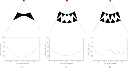
Two-dimensional schematics of the traditional bowtie filter and the proposed dynamic bowtie filter, with the square representing the x-ray source, emitting a fan beam of radiation. (a) One possible traditional bowtie filter shape and its corresponding attenuation profile. (b) The proposed bowtie, composed of triangular wedges. In this configuration, the produced attenuation profile is similar to the traditional bowtie. (c) By moving the attenuating wedges into and out of the plane, the heights of the triangles are changed such that a different attenuation profile can be produced.
To achieve dynamic control, 2N + 1 actuators are used, with the kth actuator controlling the kth triangular wedge element. Our wedge elements are shaped such that when they are scrolled into or out of the plane of the x-ray beam, triangles of different heights are present in the axial slice. Therefore, translating the wedge elements in the axial direction (or longitudinal direction, often referred to as the z-direction) directly controls ck. Figure 2 shows a three-dimensional rendering of the dynamic bowtie in two different positions, with several ck labeled. An enlarged view of a single wedge is shown in Fig. 3 which shows the triangular cross-sections.
Figure 2.
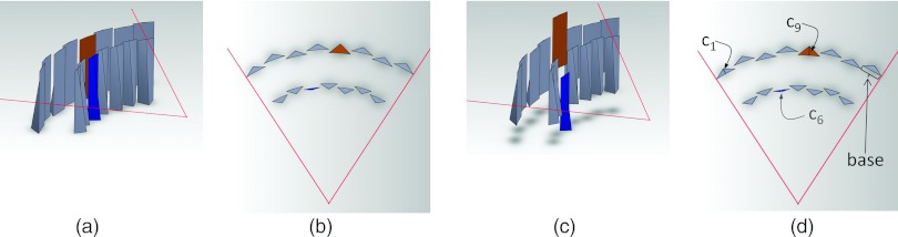
Three-dimensional rendering of the attenuator wedges. Two layers of wedges, all at the same axial location, are shown in (a) a perspective view and (b) an axial cross-section. The individual wedges may be translated in the longitudinal direction, causing them to shift in (c) the perspective view, and changing the thickness of the triangles are (d) the axial cross-section. In this case, the translation of the sixth wedge from the left downwards in (c) reduces c6, and the translation of the ninth wedge upwards increases c9. When all the wedges are independently translated, a family of piecewise-linear attenuation functions is possible.
Figure 3.

Closeup of a single wedge. Each axial cross-section through the wedge is a triangle. (a) The full wedge shape from the front. (b) Full wedge with top third removed. The exposed cross-section is a thin triangle. (c) Full wedge with two thirds removed. The exposed cross-section is a triangle with a greater height.
The dynamic bowtie would be placed a short distance away from the x-ray tube. For the purposes of this work, we use the system and bowtie parameters found in Table 1. For the dynamic range, noise and dose simulations, we assumed a monoenergetic 60 keV spectrum. For the beam hardening study, a 120 kVp polyenergetic spectrum was used. The spectrum is discretized into 10 keV intervals, starting at 30 keV. Figure 4 shows the spectrum in the original and discretized forms.
Table 1.
System and bowtie parameters.
| Field of view | 50 cm |
| Number of views | 600 |
| X-ray spectrum | Monoenergetic 60 keV, or 120 kVp |
| Source-isocenter distance | 50 cm |
| Detector-isocenter distance | 50 cm |
| Source-bowtie distance | 8 cm |
| Number of triangular wedges | 15 |
| Base (or width) of each triangle | 11.4 mm |
| Material | Iron |
| Maximum intensity reduction | 99.7% |
| Maximum thickness of wedge | 6.1 mm |
| Length of wedge in longitudinal (z) direction | 40 mm |
| Slab thickness (Δz) of scan | 4 cm |
| Minimum intensity reduction, with compensator | 60% |
| Actuator speed | 25 cm/s |
| Scan time | 300 ms |
Figure 4.

Spectrum used for the beam hardening study.
Most multislice scanners capture several centimeters of data in the longitudinal direction in a single scan. The bowtie, as presented, will produce an attenuation profile that is linear in the longitudinal direction. This can be at least partly compensated by ensuring that the thickness increase is in the anode-to-cathode direction, so the intensity modulation is opposed by the heel effect.17 Also, a compensator which varies in the longitudinal direction but has a constant thickness in fan angle can be used. Together, the dynamic bowtie filter and the compensator produce an overall attenuation that is flat in the longitudinal direction. One disadvantage of the compensation is that it imposes a minimum attenuation. If the compensator is fixed and if a wedge were completely withdrawn from the beam, then the attenuation from the slanted compensator would still remain. Thus, there would be a limit to how far the wedge can be pulled away from the beam. On the other hand, the minimum remaining material can take the place of the added x-ray beam filtration. In terms of the linear attenuation coefficient of the wedge material μwedge, the maximum thickness and longitudinal length of the wedge, twedge and lwedge, the source-to-bowtie distance SBD, the source-to-isocenter distance SID, and the z-field of view at isocenter Δz, the minimum attenuation can be calculated as
With the specifications in Table 1, 60% of the intensity of the source beam is attenuated by the dynamic bowtie. If a flat attenuation is not required, or if the compensator is allowed to move, then this minimum attenuation drawback could be eliminated. It is possible to envision a design with a portion of the compensator and some of the wedges completely withdrawn from the beam in order to maximize flux.
Other variations are possible. With larger cone angles, more creative systems could be designed to provide control over the attenuation in the longitudinal direction. It would also be possible to extend our concept to other basis functions besides triangles and thereby build up more general splines. The piecewise-linear function f(x) has discontinuities in the derivative, but a small modification to the triangular wedges would allow the provided attenuation function to be continuously differentiable, which may be desirable.
The parameters in Table 1 were chosen so that our dynamic bowtie filter could be readily constructed. Clearly, the entire bowtie could be scaled to be larger or smaller, and the choice of the material could be changed to provide more or less attenuation. The speed of the motors, which are used to scroll the wedges, are an important design consideration, and they should be chosen in conjunction with the angle of the wedge (or equivalently, the ratio between the maximum thickness of the wedge and its longitudinal length). The total rate of attenuation change possible with the system using an actuator of speed vactuator is given by
Increasing permits a more agile piecewise-linear attenuation profile, but also introduces more variation in the longitudinal direction, which in turn imposes a larger minimum attenuation if a flat attenuation profile in the longitudinal direction is needed. Conversely, the minimum attenuation could be halved if the speed of the actuators and lwedge could be doubled while twedge and μwedge are held constant. A dynamic bowtie employing more actuators and faster motors would obviously provide superior flexibility.
Calibration of the dynamic bowtie will be technically challenging but should nonetheless be possible. While it is not important to have precise control over the position of each wedge in the bowtie, it is critical that the location of each wedge is well known so that its attenuation can be compensated.
METHODS
Although the dynamic bowtie could be used to achieve any one of several objectives, in this initial study, we chose to minimize the dynamic range. We also tabulated noise and dose performance and examined beam hardening artifacts, but the control of the wedges was selected to minimize dynamic range rather than these other metrics.
The dynamic bowtie was tested on six different representative clinical datasets, including pediatric and adult patients, with anatomy including the abdomen, the shoulder, the thorax, and the head. Although certainly not exhaustive, we felt that these datasets would provide a reasonable representation of the performance of the dynamic bowtie in typical conditions. Images were drawn from a variety of sources, including anonymized scans from a local pediatric hospital and from online image archives.18, 19 The raw data were not available. Instead, it was estimated by forward projection of 512 × 512 DICOM images.
To simplify the experiments, all simulations were conducted in two dimensions and we ignore volumetric effects. The photons were assumed to be monoenergetic at 60 keV. Although the relaxation of the monoenergetic assumption is possible, the use of a monoenergetic beam simplifies our calculations and allows for the direct application of the convex optimization techniques we used to control the dynamic bowtie. We did not model imperfections in the implementation of the dynamic bowtie and assumed that we had perfect knowledge of the piecewise-linear attenuation profile. Possible imperfections include stochastic noise in the actuators and wedge shapes that do not have perfect triangular cross-sections. The achievable profiles were limited only by the parameters of the wedges listed in Table 1. Relaxing these assumptions will be important for future work, but we did not believe that they would fundamentally change the main results of this study.
The dynamic bowtie was compared to a reference bowtie similar to that found in commercial scanners. A different bowtie was used in the case of the head scan. The reference bowties are plotted in Fig. 5.
Figure 5.

Attenuation of the head and body bowties used as the static, reference bowties in this work.
Dynamic range optimization
We define dynamic range as the ratio of the intensity detected in the least and most attenuated entries in the sinogram. For example, if the dynamic range is 10, then maximum signal received by any detector channel in any view across all views is ten times greater than the minimum signal received by any channel in any view.
The dynamic range achieved depends greatly on the algorithm used to control the individual wedge elements. Suboptimal control will lead to suboptimal dynamic range performance. The question of how to control the bowtie is certainly a significant one. In this work, we assumed that prior knowledge of the patient is available and we sought to quantify the best performance possible under these conditions. Specifically, we assumed that a low-dose prescan CT of the patient was already available, and we solved an optimization problem whose objective was to minimize the dynamic range. We did not include noise in the CT prescan because we do not expect noise in the prescan to materially change our results.
The task of dynamic range minimization was cast as a convex optimization problem. Convex optimization problems have the advantage of being tractable and relatively straightforward to solve, and solutions can be generated with guaranteed optimality. We used the CVX convex optimization package.20, 21 The attenuation for any given ray in the sinogram can be decomposed into two parts: the intrinsic object (or patient) attenuation, and the added attenuation from the bowtie. The object attenuation is provided by the prescan. The added bowtie attenuation is modeled as that from component wedges in each view. With M bowtie wedges and N views, the added bowtie attenuation could be calculated as a linear combination of MN different images. To be precise, let θ be the continuous fan angle and v be the discrete view number. Let w be the half-width of the bowtie element triangle in radians. Then we can define
Now we can cast our optimization problem into the convex formulation
While dynamic range as previously defined is , we have chosen to minimize its logarithm in order to simplify the objective function. Note that tube current modulation is not used here because the system can achieve a similar effect by increasing or decreasing the thickness of all the wedges simultaneously. However, in a physical implementation, tube current modulation would be used in order to reduce the thermal load on the anode. The is a regularization term with ɛ being a very small positive constant. The purpose of this regularization term is to enforce a preference for greater flux. Without this regularization term, the optimization algorithm could add a positive constant to every cij without affecting the objective function. The regularization term is small enough so that its effect on the objective function is unnoticeable.
smax is a constant, which determines the rate of change of the triangle functions as a function of view angle. It can be calculated as , where is the maximum rate of attenuation change permissible for a given wedge using the motor, and Δt is the time between views. For simplicity, we do not model acceleration limits on the motors but only velocity, although a limit on acceleration could be included in the convex optimization framework. cmax is a constant that sets the maximum attenuation that can be imposed by the dynamic bowtie and is derived from the maximum intensity reduction (Table 1).
In order to decrease the computational complexity, the optimization problem was solved on a low-resolution sinogram with only one-third of the views. The wedge trajectories were extracted from this downsampled problem and were then upsampled to determine the high-resolution padded.
A perfect dynamic bowtie would be able to completely flatten the dynamic range. In practice, we find that the finite number of wedges limits the dynamic range reduction possible. With current system specifications and for the datasets we studied, the bottleneck to further dynamic range reduction was in the number of wedges, but we have found empirically that the speed of the actuators must also increase to realize further dynamic range reduction as the number of wedges increases.
As a reference, we compared the dynamic bowtie to the reference, static bowtie with tube current modulation. Note that in this study the dynamic bowtie modulates the incident intensity in both fan and view angles. As mentioned above, no mA modulation was employed with the dynamic bowtie. Inclusion of mA modulation to reduce x-ray tube heating is straightforward. The dynamic range of the reference bowtie depends in part on the tube current modulation scheme used, but the dynamic range of the entire scan will never be lower than the dynamic range of any given view, and the dynamic range of any given view is unaffected by tube current modulation. Therefore, the maximum dynamic range of any view serves as the best possible performance of the reference system, regardless of the tube current modulation algorithm used. The actual dynamic range in practice will depend on the agility of the mA control.
Dose and noise
With the tube current modulation profile and the trajectories of the dynamic bowtie calculated previously, we determined both the radiation dose delivered and the quantum noise of the resulting scan. The variance at each pixel in the reconstruction was produced by weighted, unfiltered backprojection of the variance of each individual ray, scaled by a constant that depends on the deapodization kernel used.22 The variance of each ray, in turn, was found by assuming Poisson statistics on the detected flux (i.e., assuming zero electronic noise). In calculating the noise statistics, we used a direct fan-beam reconstruction algorithm.
The radiation dose was found using Monte Carlo simulations with the GEANT4 software package.23 To simplify the calculations, the original DICOM image was downsampled to 128 × 128 pixels. The two-dimensional picture was extruded by 20 cm in the z-direction in order to better model through-plane Compton scattering. The 3D dose distribution was integrated in the longitudinal direction, thereby estimating the dose from a volumetric scan. The bowtie itself was modeled as being purely attenuating, and photons that underwent Compton scattering in the bowtie were ignored. To convert the DICOM images to parameterize the dose calculations, pixels less than −700 HU were regarded as air. Pixels between −700 and 200 HU were regarded as being composed of water of the density that would produce the observed HU value. Pixels above 200 HU were regarded as being a linear combination of cortical bone and water by volume, with the linear weights determined by the need to produce the observed HU value.
As with the dynamic bowtie, the tube current modulation for the reference system was calculated by solving a similar convex optimization problem, with the primary goal of minimizing the dynamic range and with the secondary goal of minimizing the regularization term, which here was equivalent to maximizing the flux. We model tube current modulation as being equivalent to introducing a virtual amount of attenuation to all detector channels throughout the view. Let us define the virtual attenuation introduced in each view as cθ. The new total attenuation is , with
As a convex problem,
We do not model imperfections of the x-ray tube and generator that could prevent such an optimal tube current modulation from being realized. The calculated tube current modulation therefore represents a best-case scenario from the perspective of minimizing the dynamic range. We used this form of tube current modulation in order to maximize the similarity to the control of the dynamic bowtie. Different tube current modulation schemes exist which may perform better for minimizing dose.3 A more dose-efficient tube current modulation could be chosen, and in this case a proper comparison would need to be made to a dynamic bowtie driven to minimize dose.
With the dynamic bowtie, minimization of the dynamic range increases the noise of the pixels at the periphery of the object, because the flux for rays tangential to the object was kept small. In some applications, this may be disadvantageous. An alternative control scheme is to minimize the dynamic range, but only for rays, which pass through the support of the object eroded by a modest distance (e.g., 2 cm). This objective increases the flux of rays tangential to the object, which may be a more appropriate objective for real systems using energy-integrating detectors.
Beam hardening simulations
To explore whether the beam hardening effects of the dynamic bowtie would remain acceptable, we conducted a polychromatic simulation. The clinical data were segmented into air, cortical bone, and water. In order to more cleanly capture the effects of beam hardening and its correction, we did not model the tissue as being mixtures of air, water, and bone but rather segmented them in a ternary fashion. This allowed the effects of beam hardening to be more apparent without anatomical background. The images were then reconstructed in three ways: without any beam hardening corrections, with a “water” beam hardening correction in which the detected flux is converted into attenuation assuming a known path length of bowtie and an unknown path length of water, and with a two-pass beam hardening correction. The beam hardening artifacts induced by the dynamic bowtie were compared with those coming from the reference bowtie, which was assumed to be made up of water equivalent material. Although bowtie filters are not currently composed of water-equivalent material, we believe that water-equivalent material is an ideal choice for bowtie material (ignoring space and weight constraints) and provides a reasonable representation of beam hardening artifacts in real systems.
The two-pass beam hardening correction method used was similar to previous two-pass algorithms.24 Briefly, in the first pass, the incident photon count is used in conjunction with the depth and material of the bowtie penetrated to estimate the equivalent water length. We apply FBP to reconstruct a first pass image, which we then segment into mixtures of water, bone, and air depending on CT number. In the second pass, we apply a forward projection step and estimate how much bone and water each ray would have passed through, and we use these numbers to estimate the error that was made in the first pass. The result is then used as a correction.
RESULTS
Dynamic range
Table 2 summarizes the dynamic range results. In all cases, the dynamic range with the dynamic bowtie was decreased by a factor of 2.4 or more compared to optimal tube current modulation with a reference bowtie. The least dynamic range reduction was seen in the smallest objects, but for these objects the dynamic range was already small, so they may not be difficult for photon-counting detectors. In some cases, a dynamic range reduction of more than an order of magnitude was achieved.
Table 2.
Dynamic range for each dataset and for each system. The sinograms that determine the dynamic range are found in Fig. 6.
| Reference bowtie | Dynamic bowtie | ||
|---|---|---|---|
| Dataset | dynamic range | dynamic range | Ratio |
| Pediatric thorax | 60 | 8 | 7.1× |
| Pediatric abdomen | 65 | 4 | 15.6× |
| Adult thorax | 53 | 17 | 3.2× |
| Adult shoulder | 1577 | 133 | 11.9× |
| Adult head | 26 | 11 | 2.4× |
| Adult abdomen | 381 | 14 | 27.1× |
Figure 6 compares the sinogram of the reference bowtie with the sinogram of the dynamic bowtie, where the sinograms here represent total attenuation from both the object plus the bowtie and mA modulation, and not the attenuation from the object only. In qualitative terms, the attenuation sinogram of the dynamic bowtie is flattened compared to the reference bowtie. The effect of the triangular wedges can sometimes be seen as short stripes in the view direction.
Figure 6.

Attenuation sinograms from the dynamic range minimization task. The attenuation sinogram is the attenuation of the object added to the attenuation provided by the system through either the bowtie or the virtual attenuation of tube current modulation. In the dynamic attenuation sinogram, the triangular pieces of the piecewise-linear attenuation function can sometimes be seen (arrows).
Dose and noise
Figures 78 compare the observed noise distribution between the reference system, optimized first to minimize dynamic range and second to maximize flux, and the dynamic bowtie system, optimized according to the convex optimization approach previously described. Figure 7 shows the results for a dynamic bowtie which optimizes the dynamic range everywhere, whereas Fig. 8 shows the results when the dynamic range is only minimized for those rays which are not peripheral to the object. The noise distribution is reported as standard deviation of pixel value (not as the variance). To produce these figures, the flux was scaled so that the peak noise (standard deviation of the noisiest pixel) between the two systems is matched. In other words, the tube current in the dynamic bowtie system is increased or decreased in all views uniformly in order to reach the same peak noise as the reference system. Table 3 summarizes the average noise and dose information for the dynamic bowtie system following either of the two control schemes, as compared to the reference bowtie.
Figure 7.

Visualization of the relative standard deviation and dose for the dynamic bowtie and reference systems. The dynamic bowtie here minimizes dynamic range everywhere, causing the noise to often be highest near the boundary of the object and the air. This is most cleanly visualized in the adult head. Summary statistics are also provided in Table 3.
Figure 8.

Visualization of the relative standard deviation and dose for the dynamic bowtie and reference systems. The dynamic bowtie here minimizes dynamic range of rays that pass through the object support eroded by 2 cm. This removes the high noise for pixels near the edge. Summary statistics are also provided in Table 3.
Table 3.
Summary dose and noise information for the dynamic bowtie systems. “All rays” refers to the optimization problem that minimizes the dynamic range everywhere (Fig. 7), whereas “2 cm erosion” only minimizes the dynamic range for those rays which pass through pixels found in the support of the object, eroded by 2 cm (Fig. 6). All values are reported relative to the reference bowtie system. For example, optimizing for all rays, the noise map of the pediatric thorax has an average noise that is 104% of the average noise of the reference system. The dose is scaled so that the peak noise between the proposed system and the reference system is equal.
| All rays | All rays | 2 cm erosion | 2 cm erosion | |
|---|---|---|---|---|
| Dataset | average noise (%) | total dose (%) | average noise (%) | total dose (%) |
| Pediatric thorax | 104 | 108 | 114 | 90 |
| Pediatric abdomen | 103 | 103 | 125 | 78 |
| Adult thorax | 142 | 71 | 130 | 78 |
| Adult shoulder | 137 | 50 | 105 | 67 |
| Adult head | 68 | 184 | 106 | 94 |
| Adult abdomen | 101 | 112 | 124 | 80 |
The noise pattern of the two systems is qualitatively different. Recall that the systems were normalized to have the same peak noise. Therefore, a value greater than 100% in average noise indicates that the dynamic bowtie causes the noise to increase in pixels that would otherwise have low noise; i.e., it is providing a more uniform noise distribution. Whether the dynamic bowtie or reference bowtie is better depends on the clinical task, but the dynamic bowtie can be controlled to minimize the noise or dose in specific regions and thereby tailor the radiation intensity to the specified clinical task. In all cases studied, when the dynamic bowtie controls only the rays that pass through the eroded object support, the average noise is consistently greater than the reference bowtie and the total dose is consistently lower than the reference bowtie while maintaining the peak variance. A simple interpretation for this effect is that the dynamic bowtie redistributes photons so that the flux incident to the noisiest parts of the image is increased, effectively flattening the noise distribution.
Note that the results in Table 3 are the noise and dose achieved when the control objective was minimizing the dynamic range. Control to achieve specific dose and noise goals can be expected to have different performance.
Beam hardening simulations
The stylized phantom used for the beam hardening simulations showed quite severe artifacts. The results with a reference bowtie both with and without a water beam hardening correction are shown in Fig. 9. Because the stylized phantom has large sections of cortical bone, the water beam hardening correction still leaves significant artifacts. The results with the dynamic bowtie using both a water beam hardening correction and a two-pass correction are also shown. In this example, the dynamic bowtie produces artifacts that are softer in nature, but the nature of the artifacts is qualitatively different and may be less consistent across patients and slices than those resulting from the fixed bowtie. The two-pass algorithm effectively suppresses the residual artifacts.
Figure 9.

Beam hardening corrections. (a) A standard bowtie without any beam hardening corrections, (b) a standard bowtie with a water beam hardening correction, (c) a dynamic bowtie with a water beam hardening correction, and (d) the dynamic bowtie with the two-pass correction. [WL, WW] is [0, 200].
DISCUSSION AND CONCLUSIONS
Based on the mathematical starting point of producing a piecewise-linear profile using adjustable triangle functions, we developed a design of a dynamic bowtie that can be physically implemented using moveable wedges, with different axial slices of the wedge resulting in triangles of different heights. While not trivial to build, this dynamic bowtie design is conceptually simple and could be adopted in a future generation of CT scanners.
The dynamic bowtie performs best for scanners with narrow coverage in z, and in Table 1, we assumed a system with a 40 mm beam in z at isocenter, representative of common modern CT scanners. The attenuation can be made uniform in z and we believe that the dynamic bowtie should be practical for these systems. Extensions can be envisioned for larger cone angles, but in general we believe that this dynamic bowtie is not well suited for specialty cardiac scanners, which are both fast in gantry rotation time and wide in z-coverage. With current specifications the dynamic bowtie imposes a significant minimum attenuation. This can be mitigated with faster actuators, slower gantry rotation times, or narrower collimation. The dynamic bowtie may perform particularly well with systems using photon-counting detectors, which may use a smaller coverage in z for reasons of cost, slower gantry rotation times in order to collect a sufficient number of photons, and which require greater dynamic range reduction compared to conventional systems.
In simulations, the dynamic bowtie was able to significantly reduce the dynamic range by factors ranging from 2.5 to 27 depending on the part of the body studied. While the studies were far from comprehensive, these results suggest that there is significant potential of using this dynamic bowtie to enable earlier adoption of photon-counting detectors with relatively modest count rates for clinical CT. With the exception of the very challenging shoulder dataset, the new dynamic range was less than 20 across all datasets. The shoulders had the largest dynamic range with the reference system and the dynamic bowtie was able to reduce the dynamic range by over an order of magnitude. Dynamic range is only a simple predictor of image quality. Future work could model the entire imaging chain, including pulse pileup, more carefully to better predict the final image quality.
Beam hardening effects are a natural concern, especially if the wedges are made of high atomic number materials (e.g., iron). Preliminary studies on the beam hardening artifacts with the dynamic bowtie showed that they look qualitatively different from traditional systems. Even if they are lower in amplitude, they may have an unfamiliar appearance to radiologists. However, they can be largely corrected with the aid of a two-pass algorithm.
While the results we have shown here are positive and encouraging, more work is necessary to validate the concept in depth. Our simulations are neither polychromatic nor volumetric. The bowtie must also be tested on other datasets to ensure that the benefits are robust. Before the bowtie can be implemented in practice, it will be important to build a physical prototype to ensure that the wedges do not produce unexpected artifacts at the transitions. The mechanism of calibration and the mechanical stability of the bowtie will be important to study. The bowtie should be able to reduce the scatter-to-primary ratio. This could be studied with a prototype or with Monte Carlo simulations. It would also be worthwhile to study the costs and benefits associated with changing the number of wedges or the speed of the actuators.
In this work, we assumed the use of a prescan so that direct optimization of the bowtie control was possible. Other control schemes can be envisioned which rely on real-time feedback, which would eliminate the requirement of the prescan. For dynamic range reduction, a simple real-time scheme is to set a target attenuation and dynamically adjust the wedges such that in each view, the deviation from the target attenuation is minimized. With sufficiently fast actuators, the performance of this real-time control method should be close to that of direct optimization. We are currently investigating such real-time control methods in order to eliminate the need of a prescan.
So far, our work has focused on the potential of the dynamic bowtie to enable photon-counting detectors. However, even with traditional energy-integrating detectors the dynamic bowtie could be used to control radiation dose. Fundamentally, the dynamic bowtie grants the system the ability to customize the distribution of radiation to the imaging task, and, as such, the dynamic bowtie could be used to enable region-of-interest scans or to protect sensitive organs. Our previous experience with the virtual dynamic bowtie, relevant to inverse geometry systems, suggest that the magnitude of this dose reduction can be 40% or larger.15, 16
Such an increase in dose efficiency would be quite welcome. The enormous success of CT has created significant concern over the cumulative radiation delivered to the population. In the past decade, a variety of technologies have been developed and adopted in order to control the radiation dose while maintaining image quality. While important and successful, these techniques still leave room for improvement. The dynamic bowtie we have proposed has the potential to provide dose control with a new level of sophistication and may contribute to large further dose reductions.
ACKNOWLEDGMENTS
The authors would like to thank Mark Peng for his assistance and the referees for improving the quality of this manuscript. This work was supported by the National Defense Science and Engineering Fellowship, the Lucas Foundation, National Institutes of Health (NIH) Grant No. R01EB006837, and the Wallace H. Coulter Foundation.
References
- Brenner D. J. and Hall E. J., “Computed tomography—An increasing source of radiation exposure,” N. Engl. J. Med. 357(22), 2277–2284 (2007). 10.1056/NEJMra072149 [DOI] [PubMed] [Google Scholar]
- Hsieh J., Computed Tomography: Principles, Design, Artifacts, and Recent Advances (SPIE, Bellingham, WA, 2003). [Google Scholar]
- Gies M., Kalender W. A., Wolf H., Suess C., and Madsen M. T., “Dose reduction in CT by anatomically adapted tube current modulation. I. Simulation studies,” Med. Phys. 26, 2235–2247 (1999). 10.1118/1.598779 [DOI] [PubMed] [Google Scholar]
- Kalender W. A., Wolf H., and Suess C., “Dose reduction in CT by anatomically adapted tube current modulation. II. Phantom measurements,” Med. Phys. 26, 2248–2253 (1999). 10.1118/1.598738 [DOI] [PubMed] [Google Scholar]
- Tapiovaara M. J. and Wagner R., “SNR and DQE analysis of broad spectrum x-ray imaging,” Phys. Med. Biol. 30, 519–529 (1985). 10.1088/0031-9155/30/6/002 [DOI] [Google Scholar]
- Roessl E. and Proksa R., “K-edge imaging in x-ray computed tomography using multi-bin photon counting detectors,” Phys. Med. Biol. 52, 4679–4696 (2007). 10.1088/0031-9155/52/15/020 [DOI] [PubMed] [Google Scholar]
- Taguchi K., Srivastava S., Kudo H., and Barber W. C., “Enabling photon counting clinical x-ray CT,” Nuclear Science Symposium Conference Record (NSS/MIC) (IEEE, New York, NY, 2009), pp. 3581–3585.
- Taguchi K., Frey E. C., Wang X., Iwanczyk J. S., and Barber W. C., “An analytical model of the effects of pulse pileup on the energy spectrum recorded by energy resolved photon counting x-ray detectors,” Med. Phys. 37(8), 3957–3969 (2010). 10.1118/1.3429056 [DOI] [PMC free article] [PubMed] [Google Scholar]
- Arenson J. S., Ruimi D., Meirav O., and Armstrong R. H., General Electric Company, “X-ray flux management device,” U.S. patent 7,330,535 (12 Feb 2008).
- Toth T. L. and Bernstein T., General Electric Company, “Method and apparatus of modulating the filtering of radiation during radiographic imaging,” U.S. patent 6,836,535 (28 Dec 2004).
- Toth T. L., Tkaczyk J. E., and Hsieh J., General Electric Company, “Method and apparatus of radiographic imaging with an energy beam tailored for a subject to be scanned,” U.S. patent 7,076,029 (11 July 2006).
- Szczykutowicz T. P. and Mistretta C., “Practical considerations for intensity modulated CT,” Proc. SPIE 8313, 83134E (2012). 10.1117/12.911355 [DOI] [Google Scholar]
- Hasegawa B., Naimuddin S., Dobbins J., Mistretta C., Peppler W., Hangiandreou N., Cusma J., McDermott J., Kudva B., and Melbye K., “Digital beam attenuator technique for compensated chest radiography,” Radiology 159(2), 537–543 (1986). [DOI] [PubMed] [Google Scholar]
- Peppler W., Kudva B., Dobbins J., Lee C., Vanlysel M., Hasegawa B., Mistretta C., “Digitally controlled beam attenuator,” Proc. SPIE 0347, 106–111 (1982). 10.1117/12.933815 [DOI] [Google Scholar]
- Bartolac S., Graham S., Siewerdsen J., and Jaffray D., “Fluence field optimization for noise and dose objectives in CT,” Med. Phys. 38, S2–S17 (2011). 10.1118/1.3574885 [DOI] [PubMed] [Google Scholar]
- Sperl J., Beque D., Claus B., De Man B., Senzig B., and Brokate M., “Computer-assisted scan protocol and reconstruction (CASPAR)—Reduction of image noise and patient dose,” IEEE Trans. Med. Imaging 29(3), 724–732 (2010). 10.1109/TMI.2009.2034515 [DOI] [PubMed] [Google Scholar]
- Fritz S. L. and Livingston W. H., “A comparison of computed and measured heel effect for various target angles,” Med. Phys. 9, 216–219 (1982). 10.1118/1.595074 [DOI] [PubMed] [Google Scholar]
- National Biomedical Imaging Archive (available URL: https://cabig.nci.nih.gov/tools/NCIA).
- CASIMAGE Radiology Teaching Files Database (available URL: http://pubimage.hcuge.ch).
- Grant M. and Boyd S., CVX: MATLAB software for disciplined convex programming, version 1.21 (CVX Research, Inc., Austin, TX, 2011).
- Grant M. and Boyd S., “Graph implementations for nonsmooth convex programs,” in Recent Advances in Learning and Control, edited by Blondel V., Boyd S., Kimura H. (Springer-Verlag, Berlin, Heidelberg, 2008), pp. 95–110. [Google Scholar]
- Chesler D. A., Riederer S. J., and Pelc N. J., “Noise due to photon counting statistics in computed x-ray tomography,” J. Comput. Assist. Tomogr. 1(1), 64–74 (1977). 10.1097/00004728-197701000-00009 [DOI] [PubMed] [Google Scholar]
- Agostinelli S., Allison J., Amako K., Apostolakis J., Araujo H., Arce P., Asai M., Axen D., Banerjee S., and Barrand G., “Geant4: A simulation toolkit,” Nucl. Instrum. Methods Phys. Res. A 506(3), 250–303 (2003). 10.1016/S0168-9002(03)01368-8 [DOI] [Google Scholar]
- Joseph P. M. and Spital R. D., “A method for correcting bone induced artifacts in computed tomography scanners,” J. Comput. Assist. Tomogr. 2(1), 100–108 (1978). 10.1097/00004728-197801000-00017 [DOI] [PubMed] [Google Scholar]
- Szczykutowicz T. P. and Mistretta C. A., “Design of a digital beam attenuation system for computed tomography: Part I. System design and simulation framework,” Med. Phys. 40, 021905 (12pp.) (2013). 10.1118/1.4773879 [DOI] [PMC free article] [PubMed] [Google Scholar]
- Szczykutowicz T. P. and Mistretta C. A., “Design of a digital beam attenuation system for computed tomography. Part II. Performance study and initial results,” Med. Phys. 40, 021906 (9pp.) (2013). 10.1118/1.4773880 [DOI] [PMC free article] [PubMed] [Google Scholar]