

Abstract
Early detection and targeted therapy are two major challenges in the battle against cancer. Novel imaging contrast agents and targeting approaches are greatly needed to improve the sensitivity and specificity of cancer theranostic agents. Here, we implemented a novel approach using a magnetic micromesh and biocompatible fluorescent magnetic nanoparticles (FMN) to magnetically enhance cancer targeting in living subjects. This approach enables magnetic targeting of systemically administered individual FMN, containing a single 8 nm superparamagnetic iron oxide (SPIO) core. Using a human glioblastoma mouse model, we show that nanoparticles can be magnetically retained in both the tumor neovasculature and surrounding tumor tissues. Magnetic accumulation of nanoparticles within the neovasculature was observable by fluorescence intravital microscopy in real time. Finally, we demonstrate that such magnetically enhanced cancer targeting augments the biological functions of molecules linked to the nanoparticle surface.
Many biological barriers in the body preclude systemically administered imaging contrast agents and drugs from reaching their target cells.1 Even for agents with surface targeting molecules,2 the cancer cell uptake is often much less than that of non-specific accumulation. Many cancer drugs also reach other healthy parts of the body, including the heart, and can cause undesirable side effects.3,4 Magnetic targeting has been proposed for decades to help direct drugs to localized sites.5–7 Although conceptually very simple, magnetic targeting faces many technical challenges including the fast decay of the magnetic field gradient away from the magnet which reduces available magnetic force and limits magnetic targeting to superficial tissues;5–7 thus the use of clusters of magnetic nanoparticles, or cells loaded with many magnetic nanoparticles is required.5–11 Here, we report a novel approach for magnetic targeting of individual magnetic nanoparticles containing single 8 nm SPIO core in mouse subcutaneous xenograft models. We utilized a combination of an external permanent magnet, to produce a moderate magnetic field, and an embedded magnetizable micromesh to produce very strong magnetic field gradients, that can simultaneously attract individual magnetic nanoparticles to multiple locations of the mesh. Provided that the magnetic fields are large enough to nearly saturate the mesh and nanoparticle moments, large magnetic field gradients are key to large magnetic forces, due to the dipole character of magnetic moments. Our targeting scheme allows generating modest (~0.1 T) fields but with large magnetic field gradients for magnetic actuation of single SPIOs, with actuation being an extremely challenging process due to small nanoparticle magnetic moments8,12 and, to the best of our knowledge, has never been demonstrated in a living subject. Developing such techniques is extremely meaningful as it pushes the boundary of the size and distance limitation of traditional magnetic targeting and could lead to better use of this technique in the clinic. We demonstrate, by direct observation under an intravital microscope, that such magnetic micromesh retained FMN while they are still in the cancer neovasculature or after extravasation. In addition, when using tumor angiogenic target αvβ3 integrin and its antagonist Arginine-Glycine-Aspartic Acid (RGD) as a model system,13,14 our results show that magnetic targeting of RGD-loaded FMN enhances their biological functions. In the human glioblastoma U87MG mouse subcutaneous xenograft model we used, tumor regression occurred more rapidly when using magnetic targeting (tumor signal decay half-life = 0.853 days, n=3), as compared to FMN-RGD alone (tumor signal decay half-life = 6.197 days, n=3). (Student’s t-test analysis, n=3, p<0.05)
RESULTS/DISCUSSION
Although nanoparticles synthesized through both physical fabrication and wet chemistry have demonstrated ever increasing diversity and complexity,15 nanoparticles suitable for clinical translation are rare. In this paper, the development of the nanoparticle platform is based on multifunctional fluorescent magnetic nanoparticles incorporating potentially biocompatible components. These nanoparticles each contain an SPIO core, the same material as in the clinical MRI agent Feridex® and the colloidal iron oxide for treating iron deficiency anemia.16 They are coated with a biocompatible siliceous shell, the material component similar to that used in daily Calcium supplements. The fluorescence is from covalently bonded organic fluorophores and FDA-approved fluorophores are available.17
Scheme 1 illustrates the general approach in preparing FMN. Starting from SPIO cores, a silanization shell is first grown and then covalently linked to organic fluorophores, along with bio-functional molecules such as drugs or targeting molecules. The fluorescence of the particles permits direct imaging of the particles in a living subject through an intravital microscope, while the magnetic properties are suitable for magnetic targeting. As shown in the transmission electron micrograph of Figure 1A, for nanoparticles deposited onto the TEM grid from a ready to inject solution, FMN contain individual SPIO cores and remain well-dispersed. Dynamic light scattering (DLS) measurement demonstrated that the size of silanized SPIO is 87 nm (supplementary figure 1). Since FMN made by Cy5.5 fluorophore incorporation, as used in this study, has an emission wavelength interfering with the red laser used for DLS measurement, sizes of FMN-Cy5.5 nanoparticles cannot be directly measured using DLS. However, measurement of FMN samples that incorporate green fluorophores demonstrated that incorporation of fluorophores increased the nanoparticle size by 10 nm, so a rough estimation of the size of FMN-Cy5.5 utilized in this paper is 97 nm. When such nanoparticles are systemically administered in a mouse cancer model, the fluorescence from FMN allows high-resolution fluorescent imaging of the tumor neovasculature. As shown in Figure 1B, no aggregates of nanoparticles in the blood stream were observed using optical microscopy and the FMN fluorescent signal smoothly outlines the tortuous tumor neovasculature, including the very thin capillaries that are only a few microns in diameter.
Scheme 1.
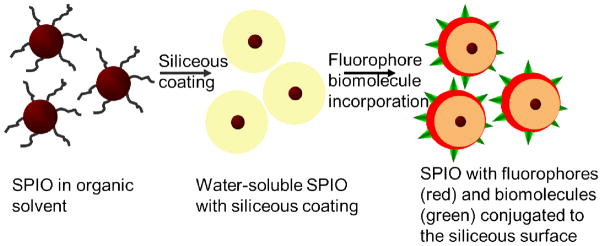
Schematic illustration of the preparation of the multifunctional nanoparticles with individual SPIO core, a siliceous coating and conjugated fluorophores and biomolecules.
Figure 1.
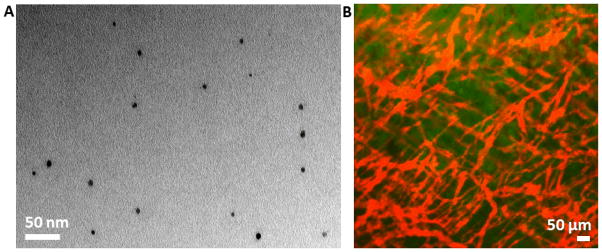
Injectable multifunctional fluorescent magnetic nanoparticles (FMN). A. Transmission electron micrograph showing FMN with individual SPIO core. B. An overlaid image showing the red fluorescence from systemically administered FMN outlining tumor neovasculature, and the green color showing EGFP-transfected human U87MG glioblastoma tumor cells.
The strong fluorescence from these FMN permits direct observation of their response under an external magnetic control in a living subject. Magnetic targeting can improve specific localization of nanoparticles when sufficient magnetic gradients are applied. This additional applied force can, in principle, help to overcome forces drawing particles away, such as viscous flow forces and other biological barriers1 and help to retain FMN before RES uptake or nonspecific binding, after systemic administration. Magnetic targeting has been developed for many uses,5–8,12 but magnetic targeting of individual nanoparticles with single SPIO cores in living subjects is extremely desirable for using small nanoparticles that can better escape the RES and penetrate tumors. This goal is challenging because a large magnetic field gradient is needed to generate a sufficient magnetic force which requires close proximity between magnets and nanoparticles, since attainable magnetic field gradients fall off very rapidly with distance. To ameliorate this limitation, we implemented an embedded magnetic micromesh that, when magnetized, can generate large magnetic field gradients distributed across a broad spatial range simultaneously. Although the use of two magnetic sources was previously applied for capturing large micron or sub-micron SPIO aggregates,18 such a method has never been exploited to magnetically localize individual SPIO or demonstrated in living subjects. Figure 2A shows the magnitude and distribution of the magnetic field gradient of an electroformed Ni micromesh under a perpendicular magnetic field of 2 KOe, as calculated using Maxwell® simulation. Ni was chosen as these meshes are readily commercially available to serve as a model for more biocompatible, magnetizable grids. A permanently magnetized mesh might also allow the elimination of the external magnet while retaining the high gradient, but the biocompatibility of permanent magnet materials is less likely than for magnetizable materials. The Ni mesh has a 76 μm pitch, 12 μm wire width and 5 μm wire thickness. The simulation shows that large magnetic field gradients of 104 to 105 T/m are generated within 10 μm of the Ni wire edges. Under such large gradients, the magnetic forces exerted on a single 8 nm SPIO cores within this proximity are large enough to overcome the viscous drag on nanoparticles within tumor vasculature (See Supplementary calculation). The field gradients from the external permanent magnet used to magnetize the mesh are much smaller, 10 T/m, and cannot exert forces large enough to accumulate FMN. The experimental set up is illustrated in Figure 2B. The Ni micromesh is placed directly on the surface of the tumor in the DSC window. The permanent magnet, with field strength of 2 KOe and a maximum field gradient of 10 T/m near the surface, is placed underneath the DSC window and magnetizes both the Ni mesh and FMN in the tumor vasculature.
Figure 2.

Maxwell simulation of the magnetic field gradient for the Ni micromesh and magnetic targeting of extravasated FMN. (A) The magnetic field gradient calculated using Maxwell®. The mesh pitch is 76 um and the magnetic field gradient is in T/m. (B) Experimental set-up for magnetic targeting. (C) Extravasated nanoparticles are adsorbed to the Ni micromesh showing red fluorescence. The image was taken 106 min after induction of the magnetic force and 152 min after nanoparticle injection. Please note that on regions of the mesh where few FMN were accumulated, the grid fluorescence is weak. (D) Control experiment shows negligible fluorescent signal from the mesh. Under the same imaging condition as C, the whole field of view is dark, as shown in the inset. The brightness and contrast of main image in D is enhanced to display the grid outline and its weak, more uniform fluorescence.
The power of this set up lies in the combined use of two magnetic entities to eliminate the dilemma related to attaining a large magnetic field gradient while maintaining a relatively large distance from a bulky external magnet. With this scheme, the ultrathin magnetizable micromesh can be inserted at the tumor location to generate a large gradient, while the permanent magnet, used to magnetize the micromesh and magnetic nanoparticles, can be placed farther away from the magnetic targeting site. In our experimental set up, the magnetized Ni micromesh generates forces which are large enough to capture FMN. Figure 2C shows that FMN accumulated at the edges of Ni wires near vasculature and that extravasated FMN outline the mesh microstructure with red FMN fluorescence, as expected from the simulated magnetic field gradient distribution of the micromesh. In the control experiment, when only the magnetic mesh was imaged under identical imaging conditions and directly displayed without any intensity adjustment, the signal of the mesh itself is almost negligible. To display the mesh outline from its intrinsic weak fluorescence, as shown in Figure 2D, the image brightness and contrast have to be adjusted, with the inset image showing the weak fluorescence using the intensity scale of Figure 2C. In Figure 2C itself, the fluorescence from the mesh is highly variable over the image, indicating that the fluorescence from brighter regions is not associated with the bare Ni mesh background. On regions of the mesh where few FMN were accumulated, the grid fluorescence is weak, and regions with varying FMN accumulation have variations in apparent width and brightness. All these features indicate that the red color on the mesh in Fig 2c is not from the mesh fluorescence itself, but rather from the accumulated FMN.
This experimental set up is also able to magnetically retain FMN within tumor neovasculature. Figure 3A shows images from three channels that detect FMN fluorescence in red, Angiosense® (circulating dye) fluorescence in blue, and EGFP tumor signal in green. This figure also shows the outline of regions of interest (ROI) that were specified and tracked for all the imaging frames in three videos, as an aid for quantitative analysis. These videos are provided in the supplementary material, each contains 60 image frames recorded at 10 s intervals, beginning 4 min after exerting the magnetic force and spanning 10 min. The average intensity of each ROI was calculated using ImageJ and plotted in Figure 3B, where it is clear that the average intensity of FMN signal in the ROI continuously increases throughout the 60 imaging frames and over the 10 min time interval. The real time accumulation of FMN under the magnetic targeting can be directly observed in the supplementary movies and the increase in average intensity over the ROI comes mostly from an increased fluorescent area, rather than increasing peak intensity. On the other hand, the Angiosense® and the tumor GFP signals show negligible increases in average intensity over ROI with time. The specific vessel shown here may be at the end of a tumor neovascular sprout, which is often located at the top of the tumor mass and is hence closest to the Ni micromesh and its strong magnetic field gradient.
Figure 3.

Magnetic targeting of FMN within tumor neovasculature. (A) Real-time observation of magnetic accumulation of FMN to the mesh edge. The three image channels are: red for FMN fluorescence, blue for Angiosense-750 fluorescence, and green for EGFP-transfected tumor signal. Each image represents the first frames of 60 frame movies capturing a 10 min magnetic targeting event starting 4 min after applying the magnetic force. Corresponding movies are shown in the supplementary material. (B) Intensity change with frame number for the ROIs outlined using the white dash in (A). (C) The angiosense™ 750 channel (blue) and the FMN channel (red) imaged 20 min after starting the magnetic field. (D) Top: Intensity contrast for ROIs that circle the nodal spot at the Ni wire edge versus that encloses the vessel area near the center of the Ni mesh hole for FMN (number on the left) and Angiosense (right). The color of the number corresponds to the color of arrows in (C). Bottom: Bar graph presenting the average intensity contrast and standard derivation for the FMN case and the Angiosense case.
Successful magnetic retention of FMN can also be observed within the well-developed neovasculature. In Figure 3C, the image channels for Angiosense® (left panel, blue color) and FMN (right panel, red color) are placed side by side for comparison. For tumor neovasculature at the center of the image, which is outlined in a relatively consistent manner by Angiosense®, punctate nodal spots at edges of Ni wires are obvious in the FMN signal channel. This is because the strong magnetic forces from the edges of Ni wires are able to retain FMN, resulting in stronger fluorescence signal at the nodal spots. The ratio of averaged FMN fluorescence intensities for a ROI that encircles the nodal spot at the Ni wire edge versus that from a ROI that encloses the vessel area near the center of the Ni mesh hole is much larger than that for the Angiosense® channel. A few pairs of such locations are indicated using colored arrows in Figure 3C. Corresponding intensity ratios for each pair are shown in the table of Figure 3D, along with a bar graph of the average values and standard deviations. The average intensity ratio for FMN signal is five times that of Angiosense® signal. This clearly demonstrates that FMN were able to respond to the external magnetic field gradient generated by the Ni micromesh and thus magnetically accumulated close to the wire edge to form nodal spots with intense fluorescence.
The magnetic targeting of FMN to the tumor region could largely impact the functions of biomolecules conjugated to FMN surfaces. Here we used RGD binding to tumor angiogenic target αvβ3 integrin as a model system, which is reported to cause apoptosis of tumor blood vessels and promote tumor regression.13 The scrambled form RAD (Arg - D - Ala – Asp)19 was utilized in control experiments. FMN-RGD demonstrated binding specificity to cultured U87MG human glioblastoma cells, as compared to FMN-RAD (Figure 4). For experiments in living subjects, we selected the intensity of tumor EGFP signal to monitor the RGD-induced effects in different experiments since nanoparticles could extravasate out of tumor leaky vessels and remain in tumor regions for extended time regardless of surface molecular specificity, in line with the enhanced permeability and retention effect of nanoparticles.20, 21 Figure 5 shows that intravenously injected FMN-RGD caused tumor regression (n=3), while tumors continued to grow after FMN-RAD injection (n=2). For FMN-RGD injection together with magnetic targeting, tumors regressed at a much faster pace (tumor signal decay half-life of 0.853 days) than when injecting FMN-RGD without any magnetic force with a tumor signal decay half-life of 6.197 days (n=3, p<0.05, Figure 5A, B, E and Supplementary Figures 2, 3). The tumor signal decay pattern under magnetic targeting is similar to that obtained by doubling the FMN-RGD dosage (Supplementary Figures 2 and 3), suggesting that expedited tumor regression under magnetic targeting is due to the retention of more FMN-RGD in the tumor region by virtue of magnetic targeting. More rigorous dosage experiments will need to be eventually performed to exactly quantify the dose equivalence of the magnetic targeting scheme.
Figure 4.
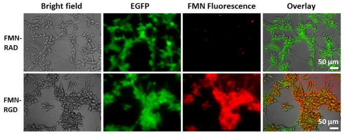
Cell staining experiments demonstrate binding specificity of FMN-RGD to cultured U87MG human glioblastoma cells in comparison with FMN-RAD. U87MG cells over-express αvβ3 integrin on the surface that bind to RGD. U87MG cells are transfected with EGFP and show green fluorescence. FMN are coated with Cy5.5 and hence have fluorescence that can be detected under the fluorescence microscope.
Figure 5.
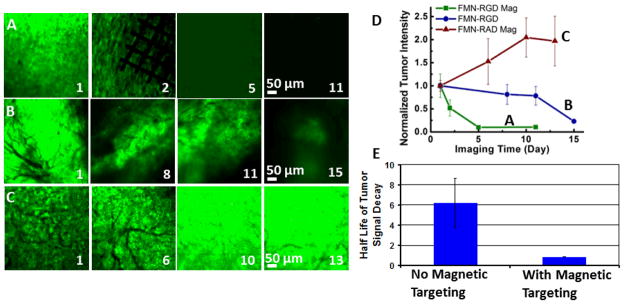
RGD-conjugated FMN in combination with external magnetic control expedites tumor regression in a U87MG human glioblastoma xenograft mouse model. (A–C) EGFP-transfected tumor image channels show tumor intensity change within days of imaging for FMN-RGD together with magnetic targeting (A), FMN-RGD without magnetic targeting (B), and FMN-RAD under magnetic targeting (C). Day 1 is the day of FMN injection and magnetic targeting. The permanent magnet was placed for 2 hours, and the Ni micromesh was removed the following day to better observe the imaging area. (D) The normalized tumor intensity vs. imaging time curves demonstrate that FMN-RGD together with magnetic targeting can expedite tumor regression (n=3, P<0.05). The fluorescence image intensity scales were set so that the brightest image within each series (A–C) was near saturation. (E) The half-lives of tumor signal decay demonstrate significantly faster tumor regression for FMN-RGD injection with magnetic targeting (n=3, 0.853 days) compared to without magnetic targeting (n=3, 6.197 days). The half-lives were obtained by fitting each of the six FMN-RGD injection curves (Figure 4D and Supplementary Figure 3) to a first order exponential decay function.
CONCLUSION
FMNs present a multitude of nanoparticle characteristics that can be used to improve the current state of the art in cancer molecular imaging and targeting. They can be formulated as multifunctional agents that offer imaging and molecular targeting functions, while also allowing externally enhanced localization through the use of magnetic forces in living subjects. The magnetic targeting in living subjects approach developed here enables manipulation of individual nanoparticles with single 8 nm SPIO cores, a formidable task in many magnetic targeting experiments. The approach presented here opens doors for utilizing individual SPIO nanoparticles, a biocompatible nanoparticle form, for targeting and imaging applications in live subjects with magnetically enhanced efficacy. This system can be further developed by making the magnetic micromesh biodegradable,22 for example, by utilizing meshes of SPIO materials in biodegradable polymeric fibrous framework, and by using multiple micromeshes to enclose or segregate tumor mass and capture drug-loaded FMN at the tumor. The combined magnetic micromesh and nanoparticle technique can improve cancer treatment through both systemic and localized chemical or biological interactions, and serve as an alternative minimally invasive procedure to surgical removal. Although rigorous experimentation and pre-clinical evaluation are required prior to their clinical use, active development of FMN and similar approaches are urgently needed for realization of nanotechnology-based solutions for challenging biomedical problems, such as earlier cancer detection and targeted therapy.23
METHODS/EXPERIMENTAL
FMN preparation
SPIO were synthesized by oxidative decomposition of iron pentacarbonyl in trimethylamine oxide, oleic acid and hexadecane.24 The average particle size is 8 nm, as measured by transmission electron microscopy (TEM) (Supplementary Figure 4). Afterward, silanization coating chemistry was developed to render SPIO water soluble and biocompatible. Briefly, mercapto/amino propyl trimethoxyl silane was added to coat the surface of SPIO by forming a crosslinked shell under basic conditions using tetramethylammonium hydroxide as the base in a methanol solution. By adjusting the quantity of silane molecules added, the shell thickness can be controlled. In this work, the size of silanized SPIO before fluorophores incorporation is 87 nm as measured by Dynamic Light Scattering technique, which provide a silanization coating thickness of roughly 40 nm. Both mercapto and amino groups are incorporated onto the nanoparticle surface. Near infrared fluorophores (Cy55) with NHS (N-hydroxysulfosuccinimide) modification (GE Healthcare) are covalently bonded to the amino groups. A small Cyclo[-Arg - Gly - Asp - D - Tyr – Lys] (RGD) that can specifically target tumor angiogenesis marker αvβ3, or its inactive control peptide Cyclo[- Arg - D - Ala - Asp - Tyr – Lys] (RAD), were bound to mercapto groups of the silanized SPIO surface using a crosslinker Sulfo-SMCC (Sulfosuccinimidyl 4-[N-maleimidomethyl]cyclohexane-1-carboxylate, Thermo Fisher Scientific).
FMN characterization
Transmission electron microscopy (TEM) imaging and characterization was performed with using a Jeol TEM1230 at 80 KV. Dynamic Light Scattering was performed on a ZetaPlus Analyzer (Brookhaven Instruments Corporation).
Animal experimentswere conducted in accordance with the ethical guidelines of the National Institutes of Health and with the approval of the Institutional Animal Care and Use Committee of Stanford University.
Intravital imaging was performed using an IV−100 intravital microscope (Olympus, Center Valley, PA). The experimental preparation included: (1) surgically implant a dorsal skinfold chamber (APJ Trading Co., Inc., Ventura, CA) onto the back of the SCID mouse (Charles River, Wilmington, MA) which is a retired male breeder weighing more than 28g, and wait for 2–3 days; (2) 1 million EGFP-transfected U87MG human glioblastoma cells were inoculated in low volume of 20 μl directly on top of the skinfold in the DSC. Tumor was allowed to grow for 10 days before imaging. On the day of intravital imaging, the mouse was anesthetized with isoflurane and positioned with the DSC fixed beneath the 10x objective of the intravital microscope. Commercial vascular dye Angiosense 750 (VisEn Medical, Woburn, MA) and FMN (with RGD or RAD) were subsequently injected into the mouse tail vain. Laser sources at 488 nm, 633 nm, and 748 nm were used for excitation. Three corresponding output channels, illustrated in this paper with green for the EGFP transfected tumor, red for HFMNs-Cy5.5, and blue for Angiosense 750 were simultaneously scanned for image acquisition. 320 and 512 pixel resolutions were selected in most imaging situations. The injection amount for Angiosense is 100 μl of original solution, which corresponds to 1.3 nanomoles. The FMN concentration was kept at 0.1 μM. A 100 μl solution of FMN (10 picomole) was injected for most experiments except for the dosage experiments, where 200 μl (20 picomole) of FMN were injected. Intravital imaging permits direct observation of the behavior FMN in living subjects.
Magnetic targeting
The observation of magnetic nanoparticle accumulation in vivo was accomplished using an intravital microscope and a tumor xenograft mouse model in a dorsal skinfold chamber (DSC). For a general experiment, EGF-transfected U87MG human glioblastoma cells (~ 1 × 10⁶) were inoculated and grown on the back of one mouse, and inside the DSC, for 10 days. Then commercial vascular dye Angiosense® 750 and FMN (with RGD or RAD) were intravenously injected, both of which outline the tumor neovasculature. The tumor area and tumor neovasculature were examined using intravital microscopy after the injection of Angiosense and FMN. Because tumor vascular growth is heterogeneous, including variations of the depth and separation of vessels, an area with the best vessel structure in the entire observation window is selected. Then a small piece (edge length ~ 3 – 8 mm) of electroformed Ni micromesh (wire width 12 μm and thickness 5 μm) was placed on top of the area. The magnetic force began when a permanent NdFeB N52 rectangular bar magnet (7.5 × 7.5 × 22 mm3) was placed beneath the DSC window on the back side of the skinfold. The permanent magnet has a field strength of 2 kOe and a maximum field gradient of 10 T/m near the surface.
Statistical analysis
The statistics for magnetic targeting (Figure 3D) were obtained from the average and standard deviation of fluorescence intensity ratios corresponding to the three pairs of colored arrows. The statistical analysis for tumor signal change with time of FMN-RGD, FMN-RAD, and magnetic targeting (Figure 4D) was based on the intensity of eight ROIs from two representative images of each imaging time point. The ROIs were selected to be within regions with the brightest tumor (EGFP) signals. The statistical analysis of the half-lives of tumor signal decay (Figure 4E) was generated by fitting each of the six FMN-RGD injection curves (Figure 4D and Supplementary Figure 3), 3 for injection under magnetic targeting and 3 for injection without magnetic targeting, to a first order exponential decay function. The statistically different tumor signal decay trends were confirmed by a student’s t-test analysis of FMN-RGD injections with and without magnetic targeting. (n=3, p<0.05).
Supplementary Material
Acknowledgments
This work was supported by grants from NCI Center for Cancer Nanotechnology Excellence (CCNE)_(1U54 CA119367-01, PI:S.S. Gambhir), a NIH Pathway to Independence Award 1K99EB008558-01 (A. Fu), and a Stanford Molecular Imaging Scholars-NIH postdoctoral training grant and the Stanford Dean’s Fellowship (B. Smith). We want to thank Dr. Ricky Tong for demonstrating the implantation of DSC on the mice. We want to thank Brian Bales from GE Global Research Center for providing the SPIO in organic solvent to us.
Footnotes
AUTHOR CONTRIBUTIONS
AF designed and performed experiments. SXW and SSG supervised experiments. RJW helped design the magnetic targeting experiments. BRS helped with the intravital microscope. JM and CE helped with the Maxwell® software. AF and RJW wrote the manuscript. All authors edited and commented on the manuscript.
Supporting Information Available: Additional information, figures, movies and calculation. This material is available free of charge via the Internet at http://pubs.acs.org
References
- 1.Sanhai WR, Sakamoto JH, Canady R, Ferrari M. Seven Challenges for Nanomedicine. Nat Nanotechnol. 2008;3:242–244. doi: 10.1038/nnano.2008.114. [DOI] [PubMed] [Google Scholar]
- 2.Liu Z, Cai W, He L, Nakayama N, Chen K, Sun X, Chen X, Dai H. In Vivo Biodistribution and Highly Efficient Tumour Targeting of Carbon Nanotubes in Mice. Nat Nanotechnol. 2007;2:47–52. doi: 10.1038/nnano.2006.170. [DOI] [PubMed] [Google Scholar]
- 3.Albini A, Pennesi G, Donatelli F, Cammarota R, Flora SD, Noonan DM. Cardiotoxicity of Anticancer Drugs: The Need for Cardio-Oncology and Cardio-Oncological Prevention. JNCI. 2010;102:14–25. doi: 10.1093/jnci/djp440. [DOI] [PMC free article] [PubMed] [Google Scholar]
- 4.Force T, Krause DS, Van Etten RA. Molecular Mechanisms of Cardiotoxicity of Tyrosine Kinase Inhibition. Nat Rev Cancer. 2007;7:332–344. doi: 10.1038/nrc2106. [DOI] [PubMed] [Google Scholar]
- 5.Barnett BP, Arepally A, Karmarkar PV, Qian D, Gilson WD, Walczak P, Howland V, Lawler L, Lauzon C, Stuber M, et al. Magnetic Resonance-guided, Real Time Targeted Delivery and Imaging of Magnetocapsules Immunoprotecting Pancreatic Iislet Cells. Nat Med. 2007;13:986–991. doi: 10.1038/nm1581. [DOI] [PubMed] [Google Scholar]
- 6.Meyers PH, Cronic F, Nice CM., Jr Experimental Approach in the Use and Magnetic Control of Metallic Iron Particles in the Lymphatic and Vascular System of Dogs as a Contrast and Isotopic Agent. Am J Roentg. 1963;90:1068–1077. [PubMed] [Google Scholar]
- 7.Pankhurst QA, Thanh NKT, Jones SK, Dobson J. Progress in Applications of Magnetic Nanoparticles in Biomedicine. J Phys D: Appl Phys. 2009;42:224001. [Google Scholar]
- 8.Dobson J. Remote control of Cellular Behaviour with Magnetic Nanoparticles. Nat Nanotechnol. 2008;3:139–143. doi: 10.1038/nnano.2008.39. [DOI] [PubMed] [Google Scholar]
- 9.Cheng KLTS, Malliaras K, Davis D, Zhang Y, Marban E. Magnetic Targeting Enhances Engraftment and Functional Benefit of Iron-Labeled Cardiosphere-Derived Cells in Myocardial Infarction. Circ Res. 2010;106:1570–1581. doi: 10.1161/CIRCRESAHA.109.212589. [DOI] [PMC free article] [PubMed] [Google Scholar]
- 10.Namiki Y, NT, Yoshida H, Ishii Y, Tsubota A, Koido S, Nariai K, Mitsunaga M, Yanagisawa S, Kashiwagi H, Mabashi Y, et al. Novel Magnetic Crystal-lipid Nanostructure for Magnetically Guided in vivo Gene Delivery. Nat Nanotechnol. 2009;4:598–606. doi: 10.1038/nnano.2009.202. [DOI] [PubMed] [Google Scholar]
- 11.Galanzha EISEV, Kelly T, Kim J, Yang L, Zharov VP. In Vivo Magnetic Enrichment and Multiplex Photoacoustic Detection of Circulating Tumour Cells. Nat Nanotechnol. 2009;4:855–860. doi: 10.1038/nnano.2009.333. [DOI] [PMC free article] [PubMed] [Google Scholar]
- 12.Mannix RJ, Kumar S, Cassiola F, Montoya-Zavala M, Ingber DE. Nanomagnetic Actuation of Receptor-Mediated Signal Transduction. Nat Nanotechnol. 2008;3:36–40. doi: 10.1038/nnano.2007.418. [DOI] [PubMed] [Google Scholar]
- 13.Brooks PC, Montgomery AMP, Rosenfeld M, Reisfeld RA, Hu T, Klier G, Cheresh DA. Integrin Antagonists Promote Tumor Regression by Inducing Apoptosis of Angiogenic Blood Vessels. Cell. 1994;79:1157–1164. doi: 10.1016/0092-8674(94)90007-8. [DOI] [PubMed] [Google Scholar]
- 14.Janssen ML, Oyen WJ, Dijkgraaf I, Massuger LF, Frielink C, Edwards DS, Rajopadhye M, Boonstra H, Corstens FH, Boerman OC. Tumor Targeting with Radiolabeled αvβ3 Integrin Binding Peptides in a Nude Mouse Model. Cancer Res. 2002;62:6146–6151. [PubMed] [Google Scholar]
- 15.Yin Y, Alivisatos AP. Colloidal Nanocrystal Synthesis and The Organic-Inorganic Interface. Nature. 2005;437:664–670. doi: 10.1038/nature04165. [DOI] [PubMed] [Google Scholar]
- 16.Wallerstein RO. Intramuscular Iron for the Treatment of Iron Deficiency Anemia in Infancy. J Pediatr. 1956;49:173–176. doi: 10.1016/s0022-3476(56)80031-0. [DOI] [PubMed] [Google Scholar]
- 17.Alford R, Simpson HM, Duberman J, Hill GC, Ogawa M, Regino C, Kobayashi H, Choyke PL. Toxicity of Organic Fluorophores Used in Molecular Imaging: literature review. Mol Imaging. 2009;8:341–354. [PubMed] [Google Scholar]
- 18.Yellen BB, Forbes ZG, Halverson DS, Fridman G, Barbee KA, Chorny M, Levy R, Friedman G. Targeted Drug Delivery to Magnetic Implants for Therapeutic Applications. J Magn Magn Mater. 2005;293:647–654. [Google Scholar]
- 19.Smith BR, Cheng Z, De A, Koh AL, Sinclair R, Gambhir SS. Real-time Intravital Imaging of RGD-Quantum Dot binding to luminal Endothelium In Mouse Tumor Neovasculature. Nano Lett. 2008;8:2599–2606. doi: 10.1021/nl080141f. [DOI] [PMC free article] [PubMed] [Google Scholar]
- 20.Bartlett DW, Su H, Hildebrandt IJ, Weber WA, Davis ME. Impact of Tumor-Specific Targeting On the Biodistribution and Efficacy of siRNA Nanoparticles Measured by Multimodality In Vivo Imaging. PNAS. 2007;104:15549–15554. doi: 10.1073/pnas.0707461104. [DOI] [PMC free article] [PubMed] [Google Scholar]
- 21.Smith BR, Cheng Z, De A, Rosenberg J, Gambhir SS. Dynamic Visualization of RGD-Quantum Dot Binding to Tumor Neovasculature and Extravasation In Multiple Living Mouse Models Using Intravital Microscopy. Small. 2010;6:2222–2229. doi: 10.1002/smll.201001022. [DOI] [PMC free article] [PubMed] [Google Scholar]
- 22.Litt B, Rogers JA. Dissolvable Films of Silk Fibroin For Ultrathin Conformal Bio-Integrated Electronics. Nat Mat. 2010;9:2745. doi: 10.1038/nmat2745. [DOI] [PMC free article] [PubMed] [Google Scholar]
- 23.Davis ME, Zuckerman JE, Choi CHJ, Seligson D, Tolcher A, Alabi CA, Yen Y, Heidel JD, Ribas A. Evidence of RNAi In Humans From Systemically Administered siRNA Via Targeted Nanoparticles. Nature. 2010;464:1067–1070. doi: 10.1038/nature08956. [DOI] [PMC free article] [PubMed] [Google Scholar]
- 24.Bonitatebus J, Acar PJ, Yagci H. Method of Making Crystalline Nanoparticles (US) 2005 [Google Scholar]
Associated Data
This section collects any data citations, data availability statements, or supplementary materials included in this article.