Abstract
Adaptive optics (AO) ophthalmoscopes with small fields of view have limited clinical utility. We propose to address this problem in reflective instruments by incorporating a viewfinder pupil relay designed by considering pupil and image centering and conjugation. Diverting light from an existing pupil optical relay to the viewfinder relay allows switching field of view size. Design methods that meet all four centering and conjugation conditions using either a single concave mirror or with two concave mirrors forming an off-axis afocal telescope are presented. Two different methods for calculating the focal length and orientation of the concave mirrors in the afocal viewfinder relay are introduced. Finally, a 2.2 × viewfinder mode is demonstrated in an AO scanning light ophthalmoscope.
OCIS codes: (080.4035) Mirror system design, (110.1080) Active or adaptive optics, (170.3890) Medical optics instrumentation, (170.4460) Ophthalmic optics and devices
1. Introduction
Ophthalmic AO imaging allows visualization of the living retina at the microscopic scale by compensating for the monochromatic aberrations of the optics of the eye. Thanks to advances in optical design, wavefront correctors and light sources, the technology has matured to the extent that microscopic structures can be routinely imaged with research AO ophthalmoscopes [1–9] and commercial prototypes [10–12].
Most current reflective AO ophthalmoscopes can achieve only small fields of view (FOVs) compared to non-AO ophthalmoscopes, making it difficult to navigate the retina. This limitation in reflective instruments typically stems from either the small angles of incidence (and hence mirrors) required to achieve good optical performance or the small Lagrange invariant of fast resonant optical scanners. Current resonant scanners that can achieve larger scanning angles at the eye resonate at audible frequencies (e.g. 8 KHz [13]). The loud high-pitch sound of these scanners makes them undesirable. The lack of a viewfinder must be addressed for ophthalmic AO imaging to achieve its full clinical potential.
AO ophthalmoscopes can be thought of as a series of optical elements that relay the exit pupil of the eye onto a number of optical scanners, wavefront correctors, wavefront sensors, apodizing masks, etc [14–16]. We propose diverting light from one of these pupil relays onto an alternative relay that we will refer to as the viewfinder relay, with larger angular magnification and a proportionally smaller pupil magnification. The larger FOV allows searching for features of interest and accurately pinpointing the location of the smaller FOV. Although the proposed viewfinder mode would in most cases not provide as large a FOV as most clinical instruments (i.e. ≥ 15°), it would benefit from the AO correction of the monochromatic aberrations of the eye.
Diversion of light to the viewfinder relay could be achieved in at least three different ways: by moving the optical elements with optical power, by using a different wavelength with fixed dichroics, or by using moveable fold mirrors. In the first approach, the light throughput could remain unchanged if the number of optical elements used is kept constant. If the elements with optical power in the original relay have to be moved in order to switch to the viewfinder mode, their alignment, and hence the AO correction could be compromised. Using different wavelengths with fixed dichroics to incorporate the viewfinder relay to the optical setup would allow simultaneous viewing of the high- and low-magnification FOVs. This approach has the advantage of no moving parts, but results in lower light throughput and it requires an additional light source and detector. The third alternative, using moveable folding mirrors might be the cheapest and simplest to implement, because the alignment of the original relay is not affected and no additional light source(s) or detector(s) are required.
The rest of this work describes the first-order design of viewfinder relays using either one or two concave mirrors, followed by the demonstration of an afocal viewfinder relay in an AO scanning light ophthalmoscope (AOSLO).
2. Theory
There are four conditions relating pupil and image planes that should be considered in the first-order design of a reflective viewfinder relay for an AO ophthalmoscope:
-
•
Pupil plane centering. By definition, the exit pupil of the viewfinder relay is smaller than that of the original relay. In order to avoid vignetting, the viewfinder relay exit pupil needs to be contained within, but not necessarily centered with respect to the exit pupil of the original relay.
-
•
Image plane centering. By definition, the FOV of the viewfinder relay is larger than that of the original relay, and the latter is usually centered with respect to the former.
-
•
Pupil plane conjugation. In order to avoid degradation of the AO correction and/or vignetting, the exit pupil plane of the viewfinder relay should be conjugate to that of the original relay.
-
•
Image plane conjugation. In order to maintain focus when switching to the viewfinder mode, light exiting the viewfinder relay must have the same vergence as that exiting the original relay.
In practice, a viewfinder relay can be implemented meeting only some of the four conditions listed above and with an arbitrary number of optical elements. In what follows, we will discuss how to design a viewfinder relay with either one or two concave mirrors.
2.1 Single concave mirror viewfinder relay
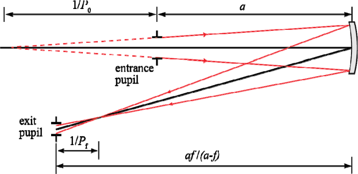
A single concave mirror can be chosen to simultaneously meet the pupil and image plane conjugation conditions, as well as one of the centering conditions, but not both. Hence, at least one additional fold mirror is required. The focal length of the concave mirror should be chosen based on the desired relative angular magnification of the viewfinder where and are the pupil magnification for the original and viewfinder relays, respectively. Image conjugation can be ensured by forcing the exit vergence of the viewfinder relay to be the same as that of the original relay.
According to paraxial ray tracing the vergence at the exit pupil of the relay when using a single concave mirror (see Fig. 1 ) is
| (1) |
where is the focal length of the mirror, is the separation between the entrance pupil and the mirror, and is the initial vergence. Using the lens equation, the definition of transverse magnification and Eq. (1) we get
| (2) |
which in terms of becomes
| (3) |
Then, using the lens equation and the definition of magnification, it follows that
| (4) |
with the separation of the mirror and the exit pupil plane of the relay being given by Eqs. (3) and (4) and the lens equation. These formulae indicate that a viewfinder relay with a single mirror can simultaneously meet the pupil and image plane conjugation conditions, when the denominator of Eq. (3) is not zero. When the denominator is zero, the original relay can be thought of as an afocal telescope, which is the case for most current reflective AO ophthalmoscopes. Thus, in what follows, we will discuss a viewfinder relay assuming an afocal original relay.
Fig. 1.
Pupil relay formed by a single concave mirror with focal length f. The mirror is a distance a from the entrance pupil, while the exit pupil is at a distance a f / (a - f). P0 and Pf are the initial and final vergences of the imaging beam.
2.2 Reflective afocal viewfinder relay
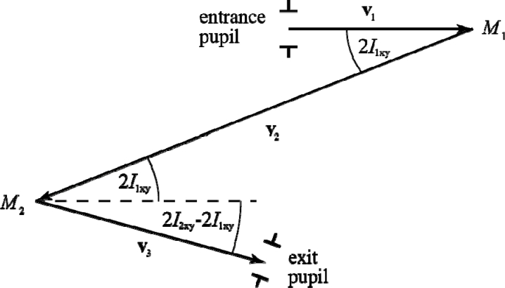
The optical axis of the original relay can be described by the three vectors depicted in Fig. 2 . For simplicity and without loss of generality it can be assumed that in this telescope, the first vector starts at the origin of coordinates and lies along the x-axis, while the second vector lies on the x-y plane. If the focal lengths of the mirrors are f1 and f2 and the angles of incidence of the optical axis onto the mirrors by I1xy, I2xy and I2z, (I1z = 0), then the three vectors in Cartesian coordinates are
Fig. 2.
Vectors used to describe the optical axis of an off-axis reflective afocal telescope formed by two concave mirrors (M1 and M2), projected on the x-y plane.
| (5) |
In the viewfinder telescope (primed variables) the reflection off the first mirror is not necessarily contained within the x-y plane, and thus an additional angle (I’1z) is required to define the vectors corresponding to the viewfinder telescope,
| (6) |
Keeping the modulus of and as and respectively, maintains the exit pupil conjugation to that of the original telescope. Forcing the modulus of to be equal to the sum of the new mirrors’ focal lengths guarantees the same image conjugation as that of the original telescope. These conditions, combined with imposing that the pupil and image planes are centered can be summarized as,
| (7) |
The six unknowns in these equations (f’1, f’2, I’1xy, I’1z, I’2xy and I’2z) determine the placement and orientation of the viewfinder relay mirrors. With some rearrangement, these equations translate into five independent equations, with the last three being summarized as a vector equation,
| (8) |
Because there are only five equations and six variables, one degree of freedom remains, which can be conveniently chosen to be the angular magnification of the viewfinder telescope relative to that of the original telescope,
| (9) |
The set of equations in Eq. (8) does not appear to have a solution that can be expressed in closed form, even when using symbolic mathematical calculation software such as Mathematica 8.0 (Wolfram Research, Champaign, Illinois, USA). An analytical solution for small angles of incidence and a numerical method for all angles of incidence can be found when the original telescope parameters are known. The solutions from both approaches are evaluated by replacing the third telescope of the AO scanning ophthalmoscope described in Ref. [17], in which and
It is important to note that when the separation between the viewfinder mirrors is different from the sum of their focal lengths the image planes of the viewfinder telescope and the original telescopes do not coincide. This means that the vergence at the exit of the viewfinder relay changes by , with being the mirror separation. If the beam entering the viewfinder telescope is not collimated, the output vergence is shifted by an additional , where is the vergence of the input beam.
2.2.1 Analytical solution for small angles of incidence
When using off axis afocal telescopes formed with concave mirrors, astigmatism can be reduced by keeping angles of incidence small [18]. Therefore, in most practical cases, the trigonometric functions in (8) can be approximated by their Taylor series, retaining only up to the quadratic terms.
Then, if the numerical values of the parameters of the original telescope and the desired magnification (2.2 × ) are substituted in, the equations in (8) are reduced to
| (10) |
that can be analytically solved by Mathematica or other symbolic calculation software. In this case, there are four solutions, of which only one is valid (f’2, I’1xy > 0).
| (11) |
It should be noted that the quadratic series expansion of the trigonometric functions of the primed arguments in Eq. (8) does not appear to have a closed form solution, other than in the particular case of an in-plane telescope (i.e. ), where each solution spans half a page. Finally, trying to solve the equations in Eq. (8) while retaining only the linear term of the trigonometric functions, leads to solutions with unacceptable errors (up to 100%).
2.2.2 Numerical solution
The second approach to finding the parameters of the viewfinder relay requires the minimization of a one-dimensional function with a single local minimum, and therefore, convergence is guaranteed. The algorithm proposed here lets the length of vary, while keeping the length of equal to that of scaled by the factor as prescribed by Eq. (5). When the quantity is close to zero (to within a tolerance acceptable to the user), the telescope associated to the corresponding vectors is afocal (i.e. image conjugation) and has the desired magnification. The focal lengths and are then equal to the norms of and respectively. For large angles of incidence, monochromatic aberrations such as astigmatism, will determine the true locations of the pupil and retinal planes since the circle of least confusion varies with angle of incidence [18].
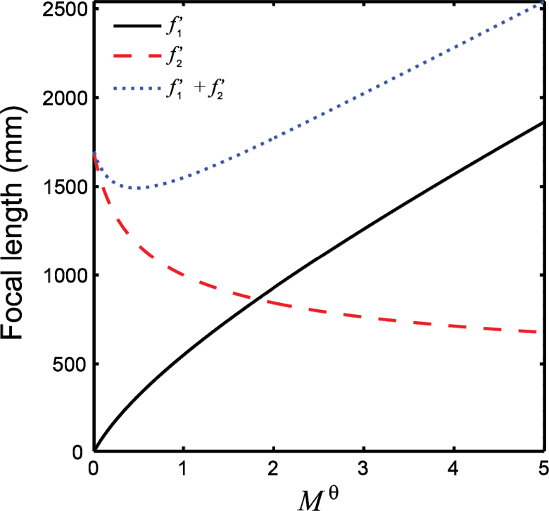
This method implemented using the fminsearch function in Matlab (Mathworks, Natick, Massachusetts, USA), agrees with the small angle approximation solution from the previous section to within 0.02%. Conversely, by creating a plot as shown in Fig. 3 , one could decide which relative angular magnification can be achieved with a given set of focal lengths that might be available off-the-shelf.
Fig. 3.
Focal lengths of the concave mirrors required to achieve a given viewfinder relay magnification Mθ calculated using the numerical approach described in section 2.2.1.
3. Methods
A viewfinder relay consisting of two spherical mirrors was incorporated to an AOSLO described in [17] and briefly evaluated by imaging the optic disc and the central fovea in two subjects.
Written informed consent was obtained after the nature and possible risks of the imaging study were explained to the subjects. Studies were approved by the Institutional Review Board at the Medical College of Wisconsin. The eye to be imaged was dilated and cycloplegia was induced with topical application of one drop of a combination of phenylephrine hydrochloride (2.5%) and tropicamide (1%). The subjects were aligned and stabilized with the use of a chin rest. The 796 nm imaging light source delivered 120 µW and the 850 nm wavefront sensing light source delivered 15 µW, both measured at the pupil of the eye. The light exposure was kept below the safe use of laser ANSI standard maximum permissible exposure [19, 20] at all times.
In principle, the viewfinder relay could replace any of the afocal telescopes between the optical scanner that limits the maximum achievable FOV and the eye. Replacing a telescope in between both scanners and the eye is preferable, as it would scale the imaging raster isotropically. In our case, the viewfinder relay replaced the telescope between the vertical optical scanner and the deformable mirror.
The parameters describing the high-magnification telescope and the viewfinder with a 2.2 × relative angular magnification are those used in the previous section. Spherical mirrors with focal lengths of 1000 and 800 mm were used instead of the calculated and respectively, as they were available to us at the time. Because the chosen focal length did not match the calculated values, the pupil and image conjugation conditions could not be met simultaneously. Prioritizing image conjugation resulted in an unstable closed-loop AO correction, and thus pupil conjugation was preferred.
Switching between the smaller FOV and the viewfinder modes required selecting two different calibrations of the AO control, due to the change in magnification. On the other hand, a viewfinder relay placed between the deformable mirror and the eye would not require re-calibrating the AO control.
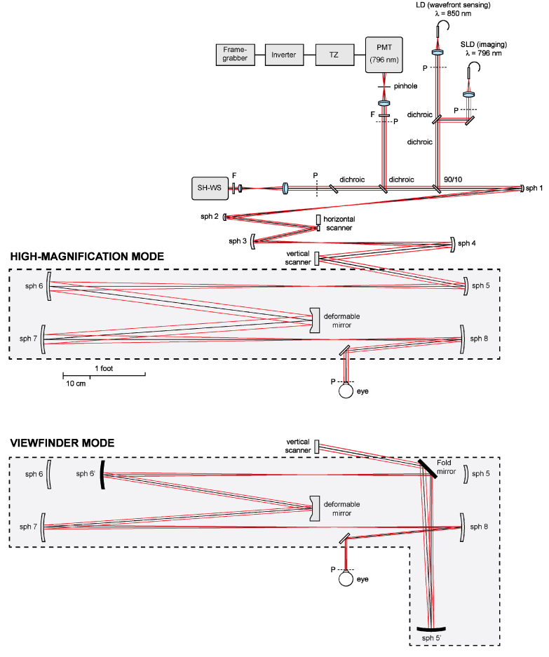
Sequences of 100-150 images were collected using a 1.75° FOV with the original AOSLO and then with the AOSLO incorporating the viewfinder mode, which had a (2.2 × 1.75°) FOV. Switching between the high-magnification and the viewfinder modes was achieved in less than 2 minutes by placing/removing a spherical mirror and a fold mirror on magnetic mounts (see Fig. 4 ), and selecting a different AO control matrix. Image stretching resulting from the sinusoidal motion of the resonant optical scanner was compensated for by estimating the distortion from images of a Ronchi ruling, and then re-sampling the images over a grid of equally spaced pixels. To increase signal to noise ratio, the image distortion due to eye motion was removed and then a number of registered frames were averaged as previously described [21].
Fig. 4.
AOSLO diagram [17], illustrating how the change between the high-magnification and viewfinder mode was implemented. In the later, a spherical mirror (sph 6’) and a fold mirror are positioned using magnetic mounts. This arrangement bypasses the afocal telescope formed by spherical mirror 5 and 6.
4. Results
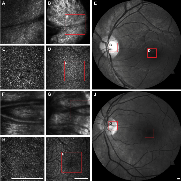
AOSLO images of the photoreceptor mosaic and optic disc of two subjects with and without the viewfinder relay are shown in Fig. 5 . The area covered in a single image when using the viewfinder mode was increased by the square of , which in this case allows surveying the retina about 5 times faster and greatly facilitates navigation to regions of interest. In addition, the increased depth of focus of the viewfinder mode, also proportional to the square of , facilitates rapid axial surveying of the retina, by reducing the number of focus steps required to cover the retinal thickness. This is particularly beneficial when imaging the retinal nerve fiber layer.
Fig. 5.
AOSLO and fundus images of subjects JC_0832 (A-E) and JC_0007 (F-J). The left and central columns show 1.75° and 2.2 × 1.75° (viewfinder mode) FOV AOSLO images, respectively, of the fovea and the optic disc. The retinal location and extent of the AOSLO images are indicated on the fundus images (right) through the red contours. All scale bars are 1° across.
There is however noticeable degradation in the viewfinder images compared to the small FOV images, in addition to that expected due to the lower spatial sampling. In our setup, the intensity and sharpness is not uniform across the viewfinder images of the photoreceptor mosaic due to vignetting by mechanical mounts. Addressing this problem would require modifying the angles of incidence in the original AOSLO, which is beyond the scope of this work. Finally, even though the same number of actuators per unit area at the pupil are being used, the AO correction is expected to be poorer due to the variations of the monochromatic aberrations across the larger FOV [22].
5. Summary
A low cost scheme for implementing a viewfinder mode in scanning and non-scanning AO reflective ophthalmoscopes based on preserving pupil and retinal image conjugation has been presented and demonstrated. The proposed viewfinder relays can be implemented with single concave mirrors and a fold mirror when the pupil relay being by-passed is not afocal, in which case two concave mirrors can be used.
The pupil and retinal image centering of the viewfinder relay can be relaxed depending on the application. For example, if the goal was to image the cone photoreceptor mosaic, then it would be sensible to take advantage of the Stiles-Crawford effect [23] and keep the pupil of the viewfinder relay centered with respect to that of the original pupil relay. Alternatively, when trying to image other structures, the pupil in the viewfinder mode could be intentionally de-centered (while avoiding vignetting) to attenuate the cone photoreceptor reflectance signal. If a viewfinder channel with a different wavelength was to be used for eye-tracking, the viewfinder’s FOV could be de-centered to a non-overlapping retinal location to reduce light exposure.
Formulae for the parameters of viewfinder relays with a single concave mirror that meet the pupil and image conjugation were derived. Two algorithms for calculating the parameters of afocal viewfinder relays meeting pupil and image conjugation and centering simultaneously were also presented and tested. Both methods agree to within 0.02% for the small angles of incidence tested. A viewfinder relay formed by two concave mirrors with a 2.2 × relative angular magnification was incorporated to an existing AOSLO and successfully tested. The proposed viewfinder modes will show transverse and axial resolution superior to that of non-AO instruments because of the AO correction, despite the reduced pupil diameter. This is essential for navigation and rapid surveying of the retina, while still being able to resolve small features that would not be resolvable in non-AO ophthalmoscopes.
Acknowledgments
Alfredo Dubra-Suarez, Ph.D., holds a Career Award at the Scientific Interface from the Burroughs Welcome Fund and a Career Development Award from Research to Prevent Blindness. This research was supported financially by the National Institutes of Health (NIH), Bethesda, Maryland ( P30EY001931) and the Glaucoma Research Foundation, San Francisco, California. This investigation was conducted in a facility constructed with support from the Research Facilities Improvement Program; grant number C06 RR016511, from the National Center for Research Resources, NIH. The authors would like to thank Joseph Carroll, Drew Scoles, Mara Goldberg and Christopher Langlo for their assistance, and Richard Rosen for providing the motivation for this work.
References
- 1.Zhang Y., Rha J. T., Jonnal R. S., Miller D. T., “Adaptive optics parallel spectral domain optical coherence tomography for imaging the living retina,” Opt. Express 13(12), 4792–4811 (2005). 10.1364/OPEX.13.004792 [DOI] [PubMed] [Google Scholar]
- 2.Zhang Y., Poonja S., Roorda A., “MEMS-based adaptive optics scanning laser ophthalmoscopy,” Opt. Lett. 31(9), 1268–1270 (2006). 10.1364/OL.31.001268 [DOI] [PubMed] [Google Scholar]
- 3.Zhang Y., Cense B., Rha J., Jonnal R. S., Gao W., Zawadzki R. J., Werner J. S., Jones S., Olivier S., Miller D. T., “High-speed volumetric imaging of cone photoreceptors with adaptive optics spectral-domain optical coherence tomography,” Opt. Express 14(10), 4380–4394 (2006). 10.1364/OE.14.004380 [DOI] [PMC free article] [PubMed] [Google Scholar]
- 4.Burns S. A., Tumbar R., Elsner A. E., Ferguson D., Hammer D. X., “Large-field-of-view, modular, stabilized, adaptive-optics-based scanning laser ophthalmoscope,” J. Opt. Soc. Am. A 24(5), 1313–1326 (2007). 10.1364/JOSAA.24.001313 [DOI] [PMC free article] [PubMed] [Google Scholar]
- 5.Ivers K. M., Li C., Patel N., Sredar N., Luo X., Queener H., Harwerth R. S., Porter J., “Reproducibility of measuring lamina cribrosa pore geometry in human and nonhuman primates with in vivo adaptive optics imaging,” Invest. Ophthalmol. Vis. Sci. 52(8), 5473–5480 (2011). 10.1167/iovs.11-7347 [DOI] [PMC free article] [PubMed] [Google Scholar]
- 6.Dubra A., Sulai Y., Norris J. L., Cooper R. F., Dubis A. M., Williams D. R., Carroll J., “Non-invasive imaging of the human rod photoreceptor mosaic using a confocal adaptive optics scanning ophthalmoscope,” Biomed. Opt. Express 2(7), 1864–1876 (2011). 10.1364/BOE.2.001864 [DOI] [PMC free article] [PubMed] [Google Scholar]
- 7.Cooper R. F., Dubis A. M., Pavaskar A., Rha J., Dubra A., Carroll J., “Spatial and temporal variation of rod photoreceptor reflectance in the human retina,” Biomed. Opt. Express 2(9), 2577–2589 (2011). 10.1364/BOE.2.002577 [DOI] [PMC free article] [PubMed] [Google Scholar]
- 8.Dees E. W., Dubra A., Baraas R. C., “Variability in parafoveal cone mosaic in normal trichromatic individuals,” Biomed. Opt. Express 2(5), 1351–1358 (2011). 10.1364/BOE.2.001351 [DOI] [PMC free article] [PubMed] [Google Scholar]
- 9.Bedggood P., Metha A., “Variability in bleach kinetics and amount of photopigment between individual foveal cones,” Invest. Ophthalmol. Vis. Sci. 53(7), 3673–3681 (2012). 10.1167/iovs.11-8796 [DOI] [PubMed] [Google Scholar]
- 10.Yamaguchi T., Nakazawa N., Bessho K., Kitaguchi Y., Maeda N., Fujikado T., Mihashi T., “Adaptive optics fundus camera using a liquid crystal phase modulator,” Opt. Rev. 15(3), 173–180 (2008). 10.1007/s10043-008-0028-6 [DOI] [Google Scholar]
- 11.K. Nozato and K. Miyata, “Adaptive optics apparatus, adaptive optics method, and imaging apparatus,” US Patent 2011/0116044 A1 (May 19 2011).
- 12.Audo I., El Sanharawi M., Vignal-Clermont C., Villa A., Morin A., Conrath J., Fompeydie D., Sahel J. A., Gocho-Nakashima K., Goureau O., Paques M., “Foveal damage in habitual poppers users,” Arch. Ophthalmol. 129(6), 703–708 (2011). 10.1001/archophthalmol.2011.6 [DOI] [PubMed] [Google Scholar]
- 13.Felberer F., Kroisamer J.-S., Hitzenberger C. K., Pircher M., “Lens based adaptive optics scanning laser ophthalmoscope,” Opt. Express 20(16), 17297–17310 (2012). 10.1364/OE.20.017297 [DOI] [PubMed] [Google Scholar]
- 14.Liang J., Williams D. R., Miller D. T., “Supernormal vision and high-resolution retinal imaging through adaptive optics,” J. Opt. Soc. Am. A 14(11), 2884–2892 (1997). 10.1364/JOSAA.14.002884 [DOI] [PubMed] [Google Scholar]
- 15.Roorda A., Romero-Borja F., Donnelly Iii W., Queener H., Hebert T. J., Campbell M. C. W., “Adaptive optics scanning laser ophthalmoscopy,” Opt. Express 10(9), 405–412 (2002). [DOI] [PubMed] [Google Scholar]
- 16.Hermann B., Fernández E. J., Unterhuber A., Sattmann H., Fercher A. F., Drexler W., Prieto P. M., Artal P., “Adaptive-optics ultrahigh-resolution optical coherence tomography,” Opt. Lett. 29(18), 2142–2144 (2004). 10.1364/OL.29.002142 [DOI] [PubMed] [Google Scholar]
- 17.Dubra A., Sulai Y., “Reflective afocal broadband adaptive optics scanning ophthalmoscope,” Biomed. Opt. Express 2(6), 1757–1768 (2011). 10.1364/BOE.2.001757 [DOI] [PMC free article] [PubMed] [Google Scholar]
- 18.Gómez-Vieyra A., Dubra A., Malacara-Hernández D., Williams D. R., “First-order design of off-axis reflective ophthalmic adaptive optics systems using afocal telescopes,” Opt. Express 17(21), 18906–18919 (2009). 10.1364/OE.17.018906 [DOI] [PMC free article] [PubMed] [Google Scholar]
- 19.Delori F. C., Webb R. H., Sliney D. H., American National Standards Institute , “Maximum permissible exposures for ocular safety (ANSI 2000), with emphasis on ophthalmic devices,” J. Opt. Soc. Am. A 24(5), 1250–1265 (2007). 10.1364/JOSAA.24.001250 [DOI] [PubMed] [Google Scholar]
- 20.ANSI, “American National Standard for safe use of lasers in research, development or testing (ANSI z136.8-2012),” (The Laser Institute of America, 2012). [Google Scholar]
- 21.A. Dubra and Z. Harvey, “Registration of 2d images from fast scanning ophthalmic instruments,” in The 4th International Workshop on Biomedical Image Registration (2010) [Google Scholar]
- 22.Bedggood P., Daaboul M., Ashman R., Smith G., Metha A., “Characteristics of the human isoplanatic patch and implications for adaptive optics retinal imaging,” J. Biomed. Opt. 13(2), 024008 (2008). 10.1117/1.2907211 [DOI] [PubMed] [Google Scholar]
- 23.Stiles W. S., Crawford B. H., “The luminous efficiency of rays entering the eye pupil at different points,” Proc. R. Soc. Lond., B 112(778), 428–450 (1933). 10.1098/rspb.1933.0020 [DOI] [Google Scholar]


