Abstract
Abstract: Microsurgeons require dexterity to make precise and stable maneuvers to achieve surgical objectives and to minimize surgical risks during freehand procedures. This work presents a novel, common path, swept source optical coherence tomography-based “smart” micromanipulation aided robotic-surgical tool (SMART) that actively suppresses surgeon hand tremor. The tool allows enhanced tool tip stabilization, more accurate targeting and the potential to lower surgical risk. Freehand performance is compared to smart tool-assisted performance and includes assessment of the one-dimensional motion tremor in an active microsurgeon’s hand. Surgeon hand tremor—the ability to accurately locate a surgical target and maintain tool tip offset distances—were all improved by smart tool assistance.
OCIS codes: (150.5758) Robotic and machine control, (170.4500) Optical coherence tomography, (060.2370) Fiber optics sensors
1. Introduction
Humans have some degree of hand tremor ranging from not noticeable for everyday tasks in most people, to incapacitating tremor in various neurodegenerative conditions. Micro-surgeons rely on excellent motor control to perform critical tasks and may have hand tremor on the order of 50-100 microns [1]. Surgical procedures on the retina require especially precise motor control to achieve surgical objectives and minimize surgical risks [2,3]. Unintended movements by the surgeon or the patient can render critical surgical tasks impossible to complete—or worse, result in catastrophic ocular injury. At the present time, certain fine micro-manipulations remain beyond the motor control of even the most skilled surgeon and all surgeons strive to minimize tremor to successfully complete microsurgical procedures. Efforts to assist surgeons in performing micron scale maneuvers continue and include but are not limited to the following: Johns Hopkins “Steady Hand” robots [4,5], handheld microsurgical robot, Micron [6,7], and a number of other active handheld and robot-assisted approaches [8,9].
Optical coherence tomography (OCT) has broad applicability as an ocular imaging modality and at present is the fastest growing segment of retina clinical practice; functional OCT has great potential to further extend the utility of OCT in clinical practice [10–12]. In addition, OCT can also be used as very precise distance sensor with high speed in biological applications, compared to other range-finding techniques such as ultrasound imaging or MRI. There has been a lot of progress in fiber optic based common path optical coherence tomography (CP-OCT) thanks to its simplicity, robustness and cost-effectiveness, which is based on a single arm interferometer design where the reference and the sample arms share a common path. Preclinical applications are emerging as evidenced by Fabry-Pérot interferometry-based fiber-optic force sensor tools that utilize common path Fourier domain optical coherence tomography [13]. A distance/proximity sensor [14], a CP-OCT-based surface topology and motion tracking system, and a conceptual micro-incision tool have all been presented as potentially significant preclinical developments [15,16]. This work presents a novel microsurgical platform, smart micromanipulation aided robotic-surgical tool (SMART) for effectively reducing the surgeon hand tremor during vitreoretinal surgery. This SMART was achieved by implementing common path, swept source optical coherence tomography (CP SS-OCT) into a prototype surgical tool that effectively cancels undesirable surgeon hand tremor, unintended instrument drift, and responds to surgical target motion. The active compensation capabilities of the surgical tool are quantitatively evaluated by direct comparisons of freehand and smart tool-assisted task performance.
2. System
2.1 Smart handheld surgical tool
This work presents the design and implementation of a CP SS-OCT based smart handheld surgical tool. The “smart” aspects of the tool are encompassed in its surface-sensing and tremor compensation capabilities and are accomplished by coupling a fiber optic CP-OCT sensing ability with a piezoelectric motor response element. The ergonomics of the prototype are broadly based on commercial products utilized in current retinal practice. Two commercial syringe needles (20-gauge and 25-gauge, BD syringe) and a piezoelectric motor (LEGS-L01S-11, PiezoMotor) represent the main components of the surgical tool at this stage of development. Further prototype designs now consider the tool’s function and performance and address manufacturing and assembly issues. The tool cover is comprised of four separate parts (front holder, back holder, tail, and joint). This design can be further reduced to simplify the manufacturing and assembly. As shown in Fig. 1(a) , convenient and robust combinations with the front holder and motor drive rod were achieved by introducing two luer-lock hypodermic needles. The inner needle was combined with the motor drive rod while the outer needle was coupled with the front holder. The function of the outer needle is as a drive supporter of the inner needle. A bare single-mode fiber for real-time distance sensing between the surgical needle tip and the surgical target is located in the bore of the inner needle. The joint part has a small hole through which a single-mode fiber (SMF28, Corning) passes to allow for OCT signal acquisition. It also functions as a connection medium between the inner needle and the motor drive rod. The piezoelectric motor has a maximum speed of 20 mm/s, maximum stroke of 55 mm, maximum force of 6.5 N, and a resolution of less than 1 nm. The motor in the back holder can be positioned by mechanical components. The minimum cross-sectional area of the tool depends primarily on the motor dimensions (22 mm x 10.8 mm x 18.7 mm). At present the tool has a length of 140 mm excluding the surgical needle and a weight of about 65 g, including the motor weight of 20 g. The front holder now allows an inner needle travel range of 12 mm. Figure 1(a) depicts a CAD-based cross-sectional image of the tool. Figure 1(b) shows the smart surgical tool adjacent to a United States quarter for scale. The magnification of the surgical needle tip shows the single-mode fiber inside the inner surgical needle.
Fig. 1.
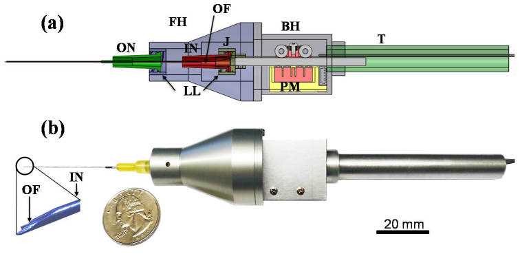
Smart handheld surgical tool. (a) CAD cross-sectional image. FH: front holder, BH: back holder, J: joint, T: tail, ON: outer needle, IN: inner needle, PM: piezoelectric motor, LL: luer-lock combination, OF: optical fiber. (b) Photo image of the tool with a quarter (USA coin) after assembly.
2.2 PID Control of the CP SS-OCT based microsurgical tool
Figure 2(a) shows the OCT system composed of a swept source, an optical circulator, and a photodetector. The laser beam is directed to the smart surgical tool through the optical circulator, and the common path interference beam returning through the distal end of the single mode fiber and the sample is redirected to the photodiode for a distance sensing. This work introduces the CP SS-OCT as a high-speed high-precision fiber-optic distance sensor to locate the surgical tip at the desired position by measuring the exact height between the surgical needle tip and the sample surface. The distal end of the single mode fiber is used as a reference plane. This CP-OCT has many advantages such as a simple and compact configuration, a disposable and interchangeable surgical tool usage, cost-effective construction, and avoidance of polarization and dispersion mismatch problems between the reference and sample arms.
Fig. 2.
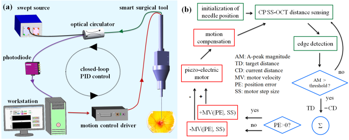
The feedback control scheme of the smart surgical tool. (a) Feedback control schematic of the common path SS-OCT-based surgical tool (b) Detailed PID based control scheme. The green boxes coordinate the OCT-based sensing and initialization; the blue diamonds provide the comparison and decision making step to activate the motor; the red boxes initiate the motion compensation steps.
The swept source (Axsun Technologies, Inc.) has a sweep repetition rate of 50 kHz, a center wavelength of 1310 nm, and a bandwidth of 110 nm providing an experimental axial resolution of 16 µm. The spectral interference detected by a photodiode is transferred to the workstation by a high-speed dual channel digitizer (AlazarTech, ATS9350), with one frame composed of 100 A-lines. One A-line with a processing speed of 500 frames per second is just utilized from 100 A-lines to sense the height. The DC components in the interference signal are eliminated by subtracting the low-pass filtered signal after ensemble averaging from the one selected A-line. The digitizer can achieve real-time acquisition with a 12-bit resolution and a sampling rate of 500 MS/s, with an 8-lane PCI Express. A quad-core workstation (Dell, T7500) handles high-speed data processing of OCT signals and real-time closed-loop control by communicating with a motor controller (PMD 90) in the LabVIEW environment.
Figure 2(a) shows the whole schematic of a CP SS-OCT based smart handheld surgical tool including the closed control loop with an update speed of 500 Hz. Figure 2(b) illustrates the schematic of the PID (Proportional, Integral, and Derivative) feedback control. Whenever the initialization of the inner surgical needle is necessary including the first usage, the needle is moved to the middle of the travel range: 12 mm. An edge detection method searching for first surface of the sample is achieved by low-pass filtering of the Fourier transformed A-line OCT signal from the multi-layered and amorphous biological sample such as a chick embryo. The magnitude of the A-scan OCT signal exceeding a predetermined threshold only triggers the motion compensation. The motor is idle with a weak OCT signal. To locate precisely the inner surgical needle to the target height, the motor movement is controlled by adjusting the combination of two motor parameters: the velocity and the step size. These are related to the PID gains determined by a function of the position and its error information. If the current position error is larger than zero, the motor moves forward and backwards if the error is negative. When the surgeon is holding the tool still or moving vertically, the feedback control system is applied to keep the offset, a constant distance from the membranous surface of a chicken embryo (Fig. 5(b)). The stabilized fiber optic based surgical tool now allows for automated surgical tool actions from a defined offset height.
3. Experiments
3.1 Tremor measurement with freehand use and its compensation
The smart surgical tool with the compensation mode turned off is a very useful tool with which to measure hand tremor. The characteristics of freehand tremor in a practicing microsurgeon are described and used as reference data for tremor requiring compensation. Two participants were assessed with the surgical tool. In our first data set, the hand tremor—while attempting to hold the instrument still—is assessed over a 5 second and 30 second time period nine times and this is compared to a 5-second compensation result on a dry phantom.
Figure 3(a) shows two representative freehand use graphs and one compensation data plot. These were selected because they had values similar to the average of the nine data sets. 30-second data plot clearly shows the low frequency unintended drift along the time, compared to 5-second data in Fig. 3(a). The inset graph shows a magnified presentation of a 5-second segment of both freehand and compensation assisted data. Each average of two freehand periods from nine data sets was 1016.16 µm (5 sec.) and 1005.9 µm (30 sec.), respectively. The average of each root mean square error (RMSE) of two periods was 37.63 µm (5 sec.) and 37.59 µm (30 sec.), respectively. The average height and RMS height error of the nine motion compensation data on the dry phantom was 999.44 µm and 5.88 µm, respectively. In the case of 30-second freehand use, the temporary tremor drift is greater than 100 µm from the target height of 1000 µm. Figure 3(b) shows the average graphs of three Fourier analyses of up to 15 Hz and position histograms for their nine height data. All Fourier transformed signals were 20th polynomial curve-fitted. The Fourier transformed graph of 30-second freehand data generally shows different frequency characteristic than 5-second freehand one, mainly due to the person’s inability to hold the tool stable over a longer period of time as shown in Fig. 3(b). Although the general shape of the amplitude graph in two freehand cases is similar, the difference is that the increase in the Fourier transform amplitude from low (3 Hz) to high (7 Hz) frequency is relatively greater in the 5-second freehand than in the 30 second freehand. For a reasonable comparison, the Fourier transformed result of 5-second compensation data should be compared with 5-second freehand data that has the same number of data samples. Compared to 5-second freehand use, involuntary hand tremor of around 0-15 Hz in the 5-second motion compensation data is significantly reduced when tested on the dry phantom model. The enhanced performance resulting from the motion compensation function is most evident in the low frequency band of less than 5 Hz. Therefore, the ability to maintain a steady target height at 1000 µm during a 5-second interval is markedly enhanced by the hand tremor suppression tool function. Moreover, the histogram of height obviously shows enhanced positioning performance by the motion compensation of the smart surgical tool even though the position distribution of a 30-second freehand is similar to the 5- second one.
Fig. 3.
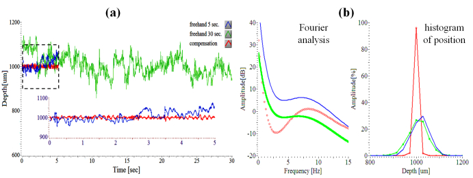
OCT-determined characteristics of surgeon tremor with freehand use. (a) Three attempting to hold steady at a defined offset height of 1000 µm: freehand use (5 seconds, 30 seconds), motion compensation on a dry phantom. Each shows the simple representative of the other nine data sets. (b) Fourier analyses and histograms of three signals.
Figure 4 shows two freehand swings including the compensation sweep movement. Seven sweep movements of 1000 µm were achieved by visual targeting on the computer screen while maintaining a constant pace by utilizing a periodically repeated sound (metronome), moving the instrument until the tracing was near to the target with the screen delay in place. The tool tip with freehand use is moved repetitively from 1000 µm to 2000 µm at two different speeds. The target height errors are comparatively large and the travel ranges vary with each cycle. The 14 peak-to-peak amplitude-based RMS distance errors of freehand1 (0.24 mm/sec) and freehand2 (1.24 mm/sec) were 53.07 and 106.12, respectively. However, the RMSE automatic repetitive sweep by the smart surgical tool was only 18.07. The smart tool therefore demonstrates that the sweep speed could increase roughly tenfold and the positioning accuracy could increase roughly threefold compared to freehand use when using a screen as the target.
Fig. 4.
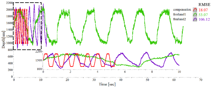
Moving the tool repetitively at a specified offset of 2000 µm from 1000 µm: two freehand swings with different speeds and a compensation mode.
3.2 Tremor Suppression on in vivo Sample
By analyzing the hand tremor of a retina surgeon, the smart surgical tool system with a closed-loop control—using edge-searching algorithms for real-time depth tracking—effectively dampened unintended tool motion, while the motion compensation function provided a theoretical extension of surgical capabilities that would utilize automatic repositioning and holding the tool motionless. The present tool is shown to be effective at maintaining tissue offset distances between 1 mm and 4 mm from the sample surface. The motion compensation capability of the tool was also evaluated in a chicken embryo model that provided a wet biological environment in which to assess practical tool function. Figures 5(a) and 5(b) show the chicken embryo model and the surgical needle including the optical fiber on the chorioallantoic membranes. Figure 5(c) demonstrates motion compensation in vivo on embryonic membranes overlying a viable animal as the target surface. The average of freehand and compensation modes were 990.85 µm (freehand) and 999.2 µm (compensation), respectively. The RMSEs were 63.82 µm (freehand) and 9.23 µm (compensation), respectively.
Fig. 5.
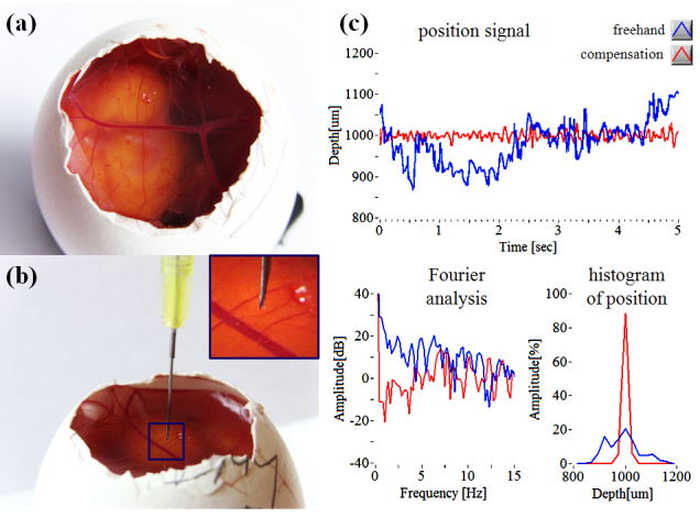
Motion compensation on chicken embryo (a) Photo image of live chicken embryo model. (b) Outer membrane of chick embryo with surgical needle. (c) Tremor suppression results: freehand tremor (blue), compensation (red).
An unintended hand tremor of around 0-15 Hz, present when used on live chick membrane, is also suppressed compared to freehand use—particularly in the low frequency band (less than 5 Hz). Dry phantom evaluation, which lacks surgical target movement, provides better performance on positioning accuracy of the target distance than wet evaluation, but assisted tool performance is still improved compared to freehand use. Use of the live chicken embryo target simulates an important variable in the surgical environment and more accurately represents the complexity of the compensation tasks required in actual surgical procedures. In this setting the smart surgical tool’s compensation system provided increased tool stability when assessing the task of maintaining a constant stand-off height compared to freehand use. A limitation of the tool at this stage of development, and hence some of our data collection, is the limited tolerance to off-perpendicular data collection. This specific limitation is being addressed in next-generation tool development.
4. Conclusions
This work presents the initial design and early testing of a novel handheld surgical tool, SMART. The SMART is based on common path swept source optical coherence tomography. In first test bed application, the tool is used to analyze one-dimensional tremor in the hand of an active retina surgeon using a dry phantom. In second application, the tool utilizes its compensation system consisting of a closed-loop control, using edge-searching algorithms, for real-time depth tracking, limitation of tool motion, and motion compensation via a piezoelectric motor to “sense” and dampen involuntary physiological hand tremor of around 0-15 Hz, particularly in the low frequency band. The tool’s ability to maintain constant offset distances is analyzed during freehand use in dry phantoms and in a chicken embryo model. In each case, performance enhancements are noted.
This first-generation SMART is intended to serve as a core platform for a set of novel surgical tools that couple active OCT distance-sensing and motion compensation technology into handheld microsurgical instruments. Clinical value would include but not be limited to more accurate instrument targeting, novel micron scale tool actions, minimization of surgical risk, novel microsurgical teaching approaches, and enhanced surgeon capabilities.
Acknowledgments
The research reported in this paper was supported by the U.S. National Institutes of Health and the National Eye Institute (NIH/NEI) Grant R01EY021540-01A1 and Research to Prevent Blindness (RPB).
References and links
- 1.Riviere C. N., Gangloff J., Mathelin M., “Robotic Compensation of Biological Motion to Enhance Surgical Accuracy,” Proc. IEEE 94(9), 1705–1716 (2006). 10.1109/JPROC.2006.880722 [DOI] [Google Scholar]
- 2.Horio N., Horiguchi M., Yamamoto N., “Triamcinolone-Assisted Internal Limiting Membrane Peeling During Idiopathic Macular Hole Surgery,” Arch. Ophthalmol. 123(1), 96–99 (2005). 10.1001/archopht.123.1.96 [DOI] [PubMed] [Google Scholar]
- 3.Murthy R. K., Chalam K. V., “Assistant-Independent OptiFlex System for Contact and Noncontact Wide-Angle Viewing in Vitreoretinal Surgery,” Arch. Ophthalmol. 128(4), 490–492 (2010). 10.1001/archophthalmol.2010.26 [DOI] [PubMed] [Google Scholar]
- 4.Taylor R., Jensen P., Whitcomb L., Barnes A., Kumar R., Stoianovici D., Gupta P., Wang Z., de Juan E., Jr, Kavoussi L., “A steady-hand robotic system for microsurgical augmentation,” Int. J. Robot. Res. 18(12), 1201–1210 (1999). 10.1177/02783649922067807 [DOI] [Google Scholar]
- 5.Balicki M., Uneri A., Iordachita I., Handa J., Gehlbach P., Taylor R., “Micro-force Sensing in Robot Assisted Membrane Peeling for Vitreoretinal Surgery,” Med Image Comput Comput Assist Interv 13(Pt 3), 303–310 (2010). [DOI] [PMC free article] [PubMed] [Google Scholar]
- 6.Becker B. C., MacLachlan R. A., Lobes L. A., Jr, Riviere C. N., “Semiautomated intraocular laser surgery using handheld instruments,” Lasers Surg. Med. 42(3), 264–273 (2010). 10.1002/lsm.20897 [DOI] [PMC free article] [PubMed] [Google Scholar]
- 7.MacLachlan R. A., Becker B. C., Cuevas Tabarés J., Podnar G. W., Lobes L. A., Jr, Riviere C. N., “Micron: an actively stabilized handheld tool for microsurgery,” IEEE Trans. Robot. 28(1), 195–212 (2012). 10.1109/TRO.2011.2169634 [DOI] [PMC free article] [PubMed] [Google Scholar]
- 8.B. Bose, A. K. Kalra, S. Thukral, A. Sood, S. K. Guha, and S. Anand, “Tremor compensation for robotics assisted microsurgery,” Proc. 13th Annu. Int. Conf. IEEE Biomedical Engineering Society 3, 1067–1068 (1992) [Google Scholar]
- 9.Ueta T., Yamaguchi Y., Shirakawa Y., Nakano T., Ideta R., Noda Y., Morita A., Mochizuki R., Sugita N., Mitsuishi M., Tamaki Y., “Robot-Assisted Vitreoretinal Surgery: Development of a Prototype and Feasibility Studies in an Animal Model,” Ophthalmology 116(8), 1538–1543 (2009). 10.1016/j.ophtha.2009.03.001 [DOI] [PubMed] [Google Scholar]
- 10.Huang D., Swanson E. A., Lin C. P., Schuman J. S., Stinson W. G., Chang W., Hee M. R., Flotte T., Gregory K., Puliafito C. A., Fujimoto J. G., “Optical coherence tomography,” Science 254(5035), 1178–1181 (1991). 10.1126/science.1957169 [DOI] [PMC free article] [PubMed] [Google Scholar]
- 11.Tao Y. K., Ehlers J. P., Toth C. A., Izatt J. A., “Intraoperative spectral domain optical coherence tomography for vitreoretinal surgery,” Opt. Lett. 35(20), 3315–3317 (2010). 10.1364/OL.35.003315 [DOI] [PMC free article] [PubMed] [Google Scholar]
- 12.Song C., Ahn M., Gweon D., “Polarization-sensitive spectral-domain optical coherence tomography using a multi-line single camera spectrometer,” Opt. Express 18(23), 23805–23817 (2010). 10.1364/OE.18.023805 [DOI] [PubMed] [Google Scholar]
- 13.Liu X., Iordachita I. I., He X., Taylor R. H., Kang J. U., “Miniature fiber-optic force sensor based on low-coherence Fabry-Pérot interferometry for vitreoretinal microsurgery,” Biomed. Opt. Express 3(5), 1062–1076 (2012). 10.1364/BOE.3.001062 [DOI] [PMC free article] [PubMed] [Google Scholar]
- 14.Kang J., Han J., Liu X., Zhang K., Song C. G., Gehlbach P., “Endoscopic Functional Fourier Domain Common Path Optical Voherence Tomography for Microsurgery,” IEEE J. Sel. Top. Quantum Electron. 16(4), 781–792 (2010). 10.1109/JSTQE.2009.2031597 [DOI] [PMC free article] [PubMed] [Google Scholar]
- 15.Zhang K., Wang W., Han J., Kang J. U., “A Surface Topology and Motion Compensation System for Microsurgery Guidance and Intervention Based on Common-Path Optical Coherence Tomography,” IEEE Trans. Biomed. Eng. 56(9), 2318–2321 (2009). 10.1109/TBME.2009.2024077 [DOI] [PMC free article] [PubMed] [Google Scholar]
- 16.Zhang K., Kang J. U., “Common-path low-coherence interferometry fiber-optic sensor guided microincision,” J. Biomed. Opt. 16(9), 095003 (2011). 10.1117/1.3622492 [DOI] [PMC free article] [PubMed] [Google Scholar]


