Abstract.
Contrast-enhanced photoacoustic (PA) imaging has been proposed to identify circulating metastatic cancer cells magnetically trapped in the vasculature. However, its sensitivity is limited by the presence of a strong blood-background signal. This technique can be further improved by the significant suppression of blood background. In the phantom study presented here, significant background suppression is demonstrated with magnetomotive photoacoustic imaging. Magnetic particles with a mean diameter of 10 μm were integrated (concentration of ) into an ink-water solution with an optical absorption coefficient of to mimic cells targeted with magnetic nanoparticles and magnetically trapped in the human vasculature. Two mechanically moveable permanent magnets were used to accumulate microparticles in the investigated solution and manipulate them within a thin, 1.6-mm-diameter Teflon tube mimicking a blood vessel. Our results clearly indicate that the undesirable background can be effectively suppressed using the difference of PA images corresponding to different locations of accumulated particles.
Keywords: photoacoustic imaging, optoacoustic imaging, metastatic cancer cells, nanoparticles, background-signal suppression, magnetomotive photoacoustic imaging
1. Introduction
Photoacoustic (PA) imaging is based on the detection of acoustic signals induced by the distribution of specific optical heterogeneities in targeted objects when irradiated by short laser pulses.1–4 Contrast in PA images is primarily determined by optical absorption, but spatial resolution is the same as in ultrasound. This contrast capability within deep biological tissue cannot be achieved by pure optical or ultrasound imaging, which both depend primarily on wave-scattering mechanisms.5 Given the MHz range of acoustic signals processed in PA imaging, sub-mm resolution is possible for routine clinical applications.
Photoacoustics is very attractive for molecular imaging because optical absorption is an efficient way to detect and differentiate specific molecules from other components. By designing a specific wavelength-selective absorption contrast agent, PA imaging can provide high sensitivity and specificity to molecular targets. By coupling specifically-designed molecular contrast agents to particular biological objects such as cancer cells, targeted cells can be specifically differentiated from the background.
However, when visualization of targeted molecules is necessary in the vasculature, PA imaging is severely challenged by the large optical absorption of hemoglobin even within the therapeutic window of optical radiation.6 The strong PA background signal from blood can mask contrast agents and make quantitative measurements of molecular concentration very difficult, especially for low concentrations of contrast agents.
The PA signal from a targeted contrast agent can be increased relative to the background by increasing its concentration, especially in model systems such as mice,7 but in humans potential toxicity limits increases in contrast-agent concentration. Indirect enhancement of the PA signal from the targeted object is much more desirable.
One method to suppress the background relative to a targeted contrast agent is to use PA measurements at multiple wavelengths to differentiate the contrast-agent absorption signature from that of the background.8–10 In particular, a two-wavelength approach using multiple contrast agents has been demonstrated to identify magnetically-trapped circulating tumor cells using PA imaging.11 As an alternative, or potential improvement to this approach, a composite contrast agent combining both magnetic and selective optical absorption properties could be used. By physically manipulating the contrast agent with an applied magnetic field, ambiguities due to fast movement of the targeted objects and multiple wavelength-related scattering variations can be greatly reduced.
Very promising results were achieved recently in multicolor PA tomography.9 The main drawback of this approach is the difference in light scattering at different wavelengths.12 In particular, the distribution of laser fluence inside the object under study cannot be considered the same at different wavelengths.13–16 This makes solution of the inverse problem quite ambiguous.
An alternate approach using magnetomotive manipulation to differentiate a coupled contrast agent from background signals has been demonstrated in Refs. 17–19. This approach, called magnetomotive photoacoustic (mmPA) imaging, uses nanoparticles with combined strong magnetic and optical-absorption properties. In previous work from our group on phantom systems, we have shown that magnetic microparticles mimicking targeted cells circulating in a peripheral vessel can be trapped, manipulated and detected with a simple mmPA imaging system. Results of these studies were limited, however, by the narrow bandwidth and limited imaging aperture of the ultrasound system used. In this paper, a very broadband, homemade polyvinylidene difluoride (PVDF) single transducer is used as the detector to demonstrate the potential background suppression possible with mmPA imaging. Interestingly, similar work on magnetomotive-aided molecular imaging has been demonstrated.20,21 Here we focus on background suppression for the ultimate application of sensitively detecting targeted rare cells trapped in the peripheral vasculature.
The primary objective of this paper is prove the concept that mmPA imaging can potentially suppress strong background signals, masking targeted cells magnetically trapped in the vasculature. In particular, the quality of background-signal suppression is demonstrated in a model system loosely mimicking in vivo conditions for PA detection of targeted cells magnetically trapped in the vasculature.
2. Materials and Methods
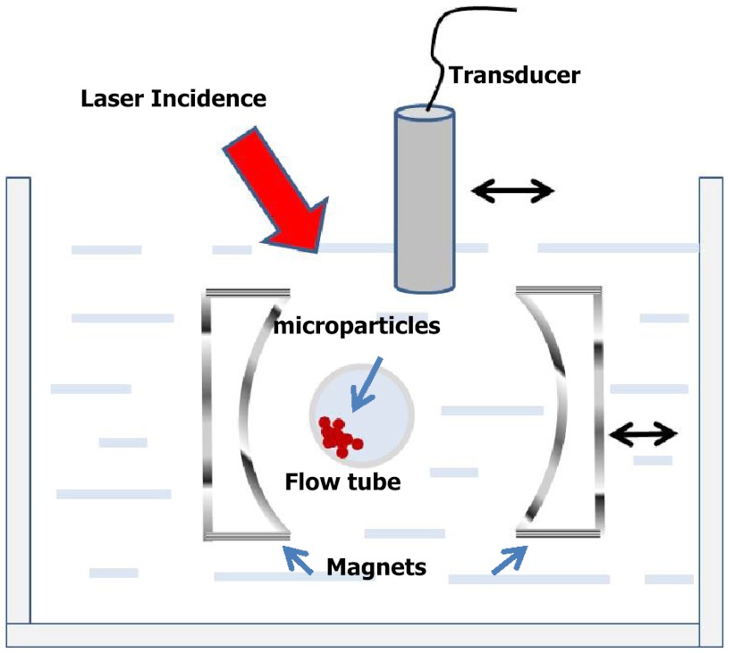
The experimental setup is shown in Fig. 1. A Teflon tube (Zeus PTFE (Teflon) Sublite Wall Tubing, Seattle, WA) with an inner diameter of 1.6 mm and a wall thickness of 38 μm was positioned in a tank filled with deionized (DI) water to mimic a blood vessel. The tube was filled with a water-based, solution of BioMag® Superparamagnetic Iron Oxide (Polysciences, Inc., Warrington, PA) particles (MP) with a diameter of about 10 μm. These particles were used in our previous studies demonstrating PA detection of trapping, and are used here to mimic cells conjugated with magnetic nanoparticles. They can be dynamically manipulated by two neodymium magnets (AY0X030-N and AY0X030-S, Jamison, PA). These magnets, separated by 4 cm with pole pieces 1.27 by 2.54 cm in cross-section, were mounted into two aluminum frames to form a dual-magnet system sitting on a translation stage so that they could be moved together laterally. The magnetic field was about 0.5 Tesla at the surface of each magnet and dropped to about 0.1 Tesla at the middle of the system. The magnetic-field gradient along the axis joining the centers of the two poles changed from at one pole to at the other pole, with zero gradient at the center of this symmetric system.
Fig. 1.
Experimental setup including flow tube, magnets for manipulation, incident-laser energy, and ultrasound imaging transducer scanned to produce a one-dimensional array used for image reconstruction.
An optical parametric oscillator (Surelite OPO Plus, Continuum, Santa Clara, CA) pumped by a frequency-doubled pulsed YAG laser (Surelite I-20, Continuum) with 5-ns pulse width was used as the laser source. The laser beam at a wavelength of 710 nm was guided to illuminate the imaged object from the top with a tilt angle of about 45 deg as shown in Fig. 1. The optical fluence at the tube surface was estimated to be based on the measured incident-laser pulse energy. The absorption spectrum for the MP is peaked in the visible range and is greatly reduced from this peak for near-infrared wavelengths. Nevertheless, there was sufficient absorption at 710 nm to demonstrate the principle of magnetic manipulation with PA readout.
Optical absorption-induced PA signals were detected with a homemade, single-channel thin strip PVDF transducer. The film thickness of 110 μm allowed highly sensitive signal detection ( using 30-fold amplification) with practically flat efficiency in the frequency range of 100 kHz to 8 MHz measured in an open-circuit regime.22 Device performance was measured using an ink solution with optical-absorption coefficient with an optically transparent, plastic plate acting as a rigid flat interface. The laser pulse was incident from the top of the plastic plate to induce a PA signal. The PVDF transducer received the PA signal from the bottom. The transfer function of the PVDF transducer was obtained from the measured PA-signal spectrum divided by the spectrum of a Gaussian pulse derivative, which is the theoretical PA signal.
The sensitive area of the transducer was fabricated as a thin strip with dimensions of 0.6 by 7 mm. The long axis was aligned along the tube direction to provide maximum spatial resolution in axial and lateral directions. Multichanneled PA detection was performed by scanning the transducer laterally to synthesize a one-dimensional array. 120 transducer positions separated by 0.4 mm were used for image reconstruction.
The inverse problem of PA tomography is the reconstruction of the laser-induced heat release , if the value of the Gruneisen parameter for the medium is known, from the PA signals measured, ideally, at each point of a detection surface. As shown in a number of recent publications,23,24 this problem has a unique solution and can be written in integral form for the three most widespread detection surfaces—a confined sphere, an infinite cylinder, and an infinite plane. This problem can be treated in either time or spatial frequency domains.
The resulting expression for the reconstructed distribution of the heat release in the time domain consists of the integral over the detection surface of the negative of the temporal derivative of the detected signals. For a more detail description of the inverse problem of PA tomography, we refer to Refs. 23, 25, and 26.
Unfortunately, if the detection surface is not confined or limited-view linear-array detectors are employed for the reconstruction, the imaged distribution of heat release is not free of artifacts.26,27 The most important artifact is the expansion of the reconstructed object in the lateral direction due to acoustic detection over a limited view.26,28
In the current work, the tube with the MP solution was placed 40 mm from the detection line. Given a total array aperture of 48 mm (120 steps), the reconstruction corresponded to a total detection angle of approximately 62 deg (i.e., f/number of approximately 0.83).
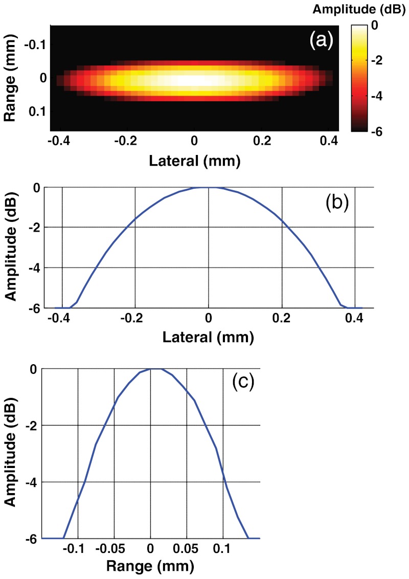
The point spread function (PSF) of the system was measured by reconstructing the image of a human hair (measured by micrometer to be 80.4 μm in diameter) placed in the same position as the tube in later experiments. As seen in Fig. 2, the axial resolution of the reconstructed PSF of the imaging system is determined by the bandwidth of the transducer used for detection and is equal to approximately 80 μm, very close to the measured size of the hair. The resolution in the lateral direction is much worse at about 650 μm, resulting from the finite width of an individual array element and the limited observation angle of the total array.28
Fig. 2.
Point spread function of a PVDF transducer array using the signal-processing parameters defined in the methods section shown as a reconstructed image (a); lateral profile (b); and axial profile (c).
First, to demonstrate the principle of physical manipulation of trapped particles, we used a solution of magnetic particles in water (concentration ). To more closely mimic the in vivo situation of particles trapped in blood, a small amount of ink was added to the initial solution to form a MP–ink-water solution. This medium was used to test the principle of background subtraction through magnetic manipulation of trapped particles. The concentration of ink in the resulting solution was chosen to provide a light-absorption coefficient of , corresponding to expected light absorption of blood in a human vessel in the near-infrared region.
3. Results
3.1. Manipulation of Magnetic Particles
In previous work we demonstrated that a mmPA system can trap and photoacoustically detect targeted objects in a circulating system.19 The total amount of trapped particles is determined by multiple physical effects, including the drag force from flow and the magnetic force between the magnets and the MPs.
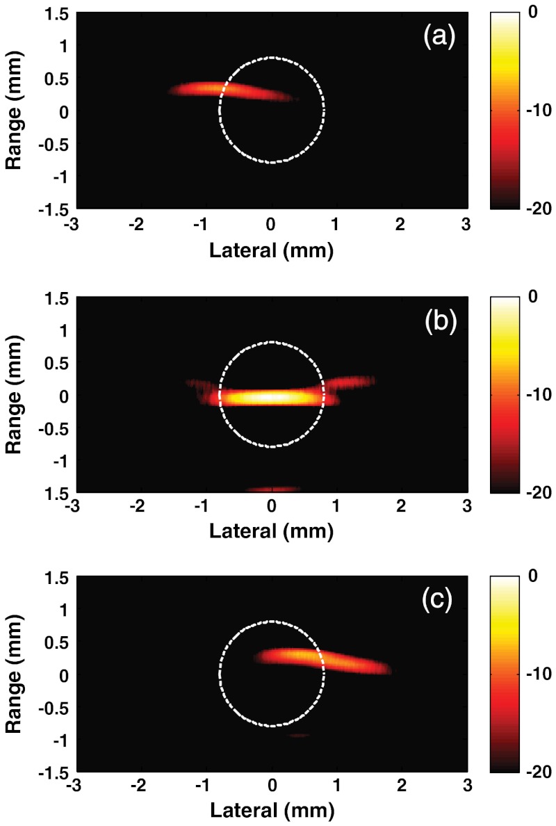
In the current study, the possibility of dynamic manipulation of trapped magnetic particles is demonstrated. First, the tube was positioned closer to the left magnet and remained stationary for a period sufficient to accumulate MPs in a region near the left wall of the tube. There was no flow in the tube, so the number of accumulated MPs is directly related to the number of particles in that region of the system. After accumulation, PA measurements were performed. Figure 3(a) presents the reconstructed image for that tube position. The MPs are clearly observed on the left side of the tube. Note that the laser fluence used for medium irradiation was 100 times smaller than medically permitted norms, which makes it very promising to use a PVDF-based detection system in vivo where strong light scattering is present from biological tissues and organs.
Fig. 3.
Photoacoustic images presented on a logarithmic scale of magnetic particles trapped within the MP-water solution: tube is closer to the left magnet (a); approximately in the middle between the magnets (b); and closer to the right magnet (c). Dashed circle drawn as an indicator of the tube.
Figure 3(b) and 3(c) shows images corresponding to the cases where the tube is positioned approximately in the middle between the magnets and closer to the right magnet, respectively. The PA imaging shapes and intensities differ for each position based on the actual distribution of particles, as determined by the details of the magnetic-field distributions at those positions. For particles trapped on the sides of the tube, the distribution is curved due to the tube walls and by the nonsymmetric magnetic field induced by focused magnets in these regions. In contrast, for particles trapped in the middle, the symmetrical magnetic field flattens, leading to a “pancake” structure of trapped particles that produces an enforced PA signal in the backward direction. Also, the PA intensity along the sides is further reduced compared to the center because of reduced optical fluence in these regions resulting from light reflection at the curved tube walls. In any event, these images clearly demonstrate the possibility of dynamically manipulating large (μm-scale) particles in mmPA imaging.
3.2. Suppression of the Background Signal
The main goal of the present work was to demonstrate that the strong background produced by blood, which is always present together with any contrast agent and can produce much stronger PA signals than those of contrast agents, can be greatly suppressed using magnetic manipulation of the contrast agent. A small amount of ink was added to the initial MP-water solution to mimic a blood background, as discussed in the methods section. The experimental setup was used to image the tube filled only with an ink-water solution without magnetic particles (i.e., background) and contrast that image to a set of images of the MP–ink-water solution.
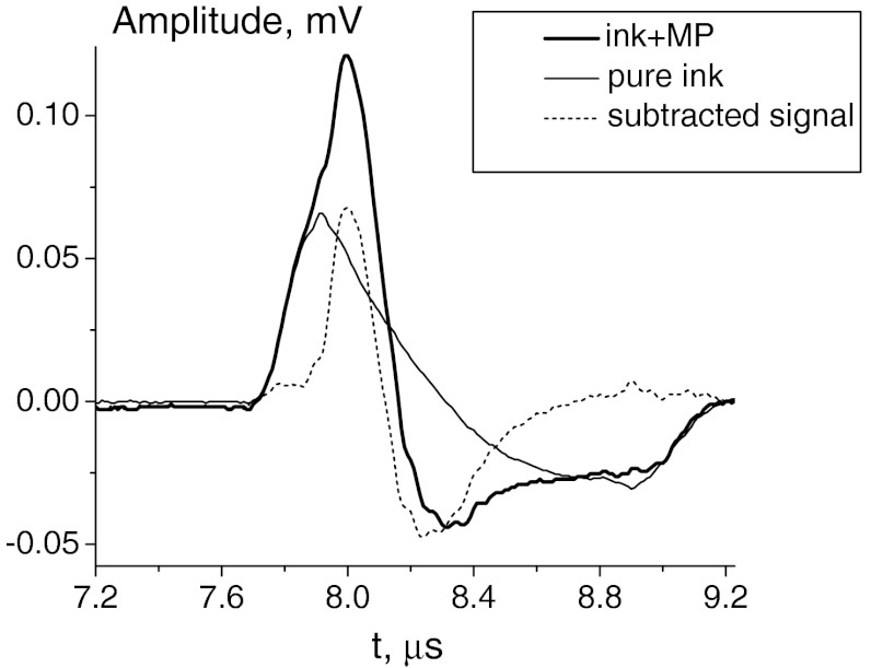
Figure 4 shows the temporal profiles of the detected PA signals corresponding to the central position of the PVDF transducer (exactly above the tube). The dotted curve corresponds to the temporal profile of the PA signal in the ink-water solution without magnetic particles. The bold solid curve represents the PA signal profile after magnetic particles are allowed to accumulate in the MP–ink-water solution with the tube in the center position of the magnets. The differential signal is calculated as the difference of the first two (i.e., subtracting the signal excited in the ink-water solution from the signal excited in the MP–ink-water solution). As seen, the signal induced by the ink background is similar in both magnitude and time response to the signal produced by only the trapped MPs. The differential signal clearly demonstrates the effect of background subtraction. By referring to the PA signal of the ink-water solution, the signal-to-noise ratio improved by about 14 dB after the subtraction under this phantom-study model condition.
Fig. 4.
Temporal profiles of the detected signals for a pure ink-water solution (dashed line), MP-ink-water solution (bold solid line ) and their difference (thin solid line). The curves shown here are for the tube located in the middle of magnets.
However, in most biomedical applications like in vivo real-time monitoring, it is very difficult, or almost impossible, to get a stable and reliable background signal. In such a case, we propose to use the mmPA method,18,19 which in simplest form simply subtracts two PA images corresponding to two different magnet positions. Presumably, the background signal does not change with magnet position, so only the signal from targeted MPs should remain.
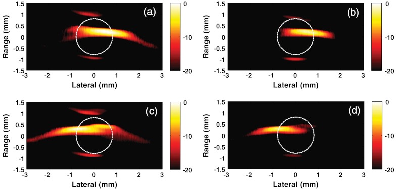
Images of MPs at two different magnet positions in the presence of the ink background are presented in Fig. 5(a) and 5(c). The differential images obtained after the subtraction of the ink background for the same magnet positions are shown in Fig. 5(b) and 5(d), respectively. Clearly, with the strong background signal from ink, it is very difficult to separate the contributions of the ink background and magnetic particles in the resulting images. We note that these images are for a relatively large number of MPs in the imaging region. For a much smaller number of particles, similar to the case when a small number of targeted cells must be detected, it would be nearly impossible to uniquely detect the contribution from the contrast agent.
Fig. 5.
Photocoustic images on a logarithmic scale of magnetic particles trapped in MP–ink-water solution: tube is closer to the right magnet in (a) and (b) and closer to the left magnet in (c) and (d); images of (a) and (c) are before subtraction of the ink background, and images of (b) and (d) are after subtraction of the ink background. Dashed circle drawn as an indicator of the tube.
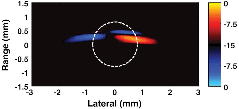
Figure 6 illustrates the main idea of mmPA imaging using different particle locations induced by magnetomotive forces to suppress undesirable background signals. Here, a differential image is generated by subtracting the image for the tube position closer to the left magnet [Fig. 5(c)] from the image for the tube position closer to right magnet [Fig. 5(a)]. It is displayed on a bipolar logarithmic scale to highlight the positions of the two locations while simultaneously suppressing the background-ink signal.
Fig. 6.
Differential image presented on a bipolar, logarithmic scale using the image of the tube with its left side close to the magnet subtracted from the image of the tube with its right side close to the magnet. Dashed circle drawn as an indicator of the tube.
Comparing this image to the component images in Fig. 5 and to the MP-water images in Fig. 3, it is clear that background suppression is substantial. Complete suppression is not possible, however, with a limited-view transducer array since the artifacts induced depend on the positions of all sources in the reconstructed image. Only if the detecting surface represents a closed surface around the object under study, individual images, and thereby their difference, will be free from artifacts. In our case the small, lusterless spot in the upper right side of the differential image is most probably created by the superposition of artifacts inherent to individual images. Nevertheless, the results presented in Fig. 6 clearly show that even for a limited-angle system, nearly complete suppression of the background is possible.
4. Discussion
An ink solution was used to mimic the optical-absorption characteristics of blood for near-infrared wavelengths. This is an approximation since at the microscale these two media differ significantly. PA signals in blood over visible and near-infrared wavelengths are dominated by the absorption characteristics of hemoglobin in blood red cells, whereas the primary PA source is graphite particles for the ink solution. Although clearly different at the microscale, at the macroscopic scale at which these measurements are made both ink and blood can be considered as homogeneous and described by their bulk physical properties.29,30 Since the Gruneisen parameter of blood is only 1.6 times higher than that of water,13,31 blood in the vasculature will produce a PA signal very similar to that recorded in the ink solution used in this study.
In this study, background signals did not change substantially during magnetomotive manipulation. This will clearly not be the case in the peripheral vasculature where background signals can vary due to flow dynamics, hematocrit and oxygenation state. Future studies will also test the hypothesis that background signals can be greatly suppressed by averaging mmPA images over small time intervals commensurate with the time constants associated with trapping and manipulation of targeted cells.
Micromagnetic particles 10 μm in diameter were used here to mimic cells targeted with magnetic nanoparticles. Future studies will use nanometer-scale magnetic particles targeted to micron-scale objects such as circulating cells and cell mimics instead of micron-scale particles.
The current magnet system was not designed to trap particles moving at physiologic flow rates typically encountered in peripheral vessels, but rather to demonstrate how trapped magnetic particles can be manipulated for mmPA imaging. The next step in our studies on trapping targeted rare cells trafficking in the vasculature will be to design and build a magnet system providing sufficient magnetic force to trap and manipulate particles flowing in peripheral vessels.
The ultimate goal for forthcoming studies is to achieve the capability of rare (as few as a single one) circulating-tumor-cell trapping and detection using mmPA imaging with the help of background suppression as described in this study. Currently, the technology to manufacture composite, or coupled, contrast agents combining magnetosensitive nanoparticles with high absorbing gold nanoshells17,32–34 or nanorods35–38 has been developed. Recent in vitro measurements demonstrated high targeting efficiency and specificity of such composite contrast agents to tumor cells and bacteria.37,38 They can also be used to target tumor cells trafficking in the vasculature. We hypothesize that cells tagged in this way can be trapped in the peripheral vasculature and detected with mmPA imaging. In fact, if the surface of a one micrometer-scale cell is completely covered by composite (highly optical absorbing and magnetosensitive) nanoparticles, its transient temperature increase by light absorption can be assumed to be less than 25 °C to ensure that targeted cells are not disrupted. This temperature increase can be obtained very easily, even with laser fluence much smaller than the medically permitted maximum. This would produce a PA signal with an amplitude of a few MPa.39 Taking into consideration ultrasound attenuation and diffraction loss during propagation,14,40 and a limited frequency band of detection, the amplitude would be reduced by at least four orders of magnitude.25,28,41 However, a focused thin-film PVDF-based transducer can detect a pressure signal on the level of ten Pa14,25 for frequencies up to 10 MHz. Therefore, a minimum 20-dB signal-to-noise ratio of the detected PA signal by a contrast-agent-targeted single tumor cell would be feasible. Furthermore, nonlinear effects of tissue thermal expansion can even provide more sensitive detection than this expectation.42,43
5. Conclusions
In the current phantom study, we have experimentally demonstrated the possibility of effective magnetomotive manipulation of μm-scale magnetosensitive particles mimicking targeted cells trapped in the peripheral vasculature. Our results clearly indicate that an undesirable strong PA background signal can be effectively suppressed using the difference of PA images corresponding to different locations of accumulated particles. This method can be used under flow conditions encountered in peripheral vessels with an appropriately-designed ultrasound detection and magnet system, and may have great potential for molecular assays of targeted metastatic cells travelling in the vasculature.
Acknowledgments
We acknowledge partial support of this work by the NIH (R01 CA131797, R01 CA140295, and T32 CA138312), the NSF (0645080), the Washington Life Sciences Discovery Fund (3292512) and the Department of Bioengineering at the University of Washington.
References
- 1.Wang L. V., Photoacoustic Imaging and Spectroscopy, CRC, Boca Raton, FL: (2009). [Google Scholar]
- 2.Sethuramana S., et al. , “Intravascular photoacoustic imaging using an IVUS imaging catheter,” IEEE Trans. Ultrason., Ferroelectr. Freq. Control 54(5), 978–986 (2007). 10.1109/TUFFC.2007.343 [DOI] [PubMed] [Google Scholar]
- 3.Ermilov S. A., et al. , “Laser optoacoustic imaging system for detection of breast cancer,” J. Biomed. Opt. 14, 024007 (2009). 10.1117/1.3086616 [DOI] [PubMed] [Google Scholar]
- 4.Li H., Wang L. V., “Photoacoustic tomography and sensing in biomedicine,” Phys. Med. Biol. 54(19), R59–R97 (2009). 10.1088/0031-9155/54/19/R01 [DOI] [PMC free article] [PubMed] [Google Scholar]
- 5.Emelianov S. Y., Li P. C., O’Donnell M., “Photoacoustics for molecular imaging and therapy,” Phys. Today 62(5), 34–39 (2009). 10.1063/1.3141939 [DOI] [PMC free article] [PubMed] [Google Scholar]
- 6.Tuchin V. V., Handbook of Optical Biomedical Diagnostics, SPIE Press, Bellingham, WA: (2007). [Google Scholar]
- 7.Jetzfellner T., et al. , “Interpolated model-matrix optoacoustic tomography of the mouse brain,” Appl. Phys. Lett. 98(16), 163701 (2011). 10.1063/1.3579156 [DOI] [Google Scholar]
- 8.Hu S., et al. , “Functional transcranial brain imaging by optical-resolution photoacoustic microscopy,” J. Biomed. Opt. 14(4), 040503 (2009). 10.1117/1.3194136 [DOI] [PMC free article] [PubMed] [Google Scholar]
- 9.Razansky D., Buehler A., Ntziachristos V., “Volumetric real-time multispectral optoacoustic tomography of biomarkers,” Nat. Prot. 6(8), 1121–1129 (2011). [DOI] [PubMed] [Google Scholar]
- 10.Huang S. W., et al. , “Differential-absorption photoacoustic imaging for contrast enhancement,” Opt. Lett. 34(16), 2393–2395 (2009). 10.1364/OL.34.002393 [DOI] [PubMed] [Google Scholar]
- 11.Galanzha E. I., et al. , “In vivo magnetic enrichment and multiplex photoacoustic detection of circulating tumour cells,” Nat. Nanotechnol. 4(12), 855–860 (2009). 10.1038/nnano.2009.333 [DOI] [PMC free article] [PubMed] [Google Scholar]
- 12.Xia J. J., et al. , “Monitoring sarcomere structure changes in whole muscle using diffuse light reflectance,” J. Biomed. Opt. 11, 040504 (2006). 10.1117/1.2234278 [DOI] [PubMed] [Google Scholar]
- 13.Duck F. A., Physical Properties of Tissue, Academic Press, London; (1999). [Google Scholar]
- 14.Pelivanov I. M., et al. , “Direct opto-acoustic in vitro measurement of the spatial distribution of laser radiation in biological media,” Quant. Electron. 36(12), 1089–1096 (2006). 10.1070/QE2006v036n12ABEH013261 [DOI] [Google Scholar]
- 15.Pifferi A., et al. , “Spectroscopic time-resolved diffuse reflectance and transmittance measurements of the female breast at different interfiber distances,” J. Biomed. Opt. 9(6), 1143–1151 (2004). 10.1117/1.1802171 [DOI] [PubMed] [Google Scholar]
- 16.Taroni P., et al. , “In vivo absorption and scattering spectroscopy of biological tissues,” Photochem. Photobiol. Sci. 2(2), 124–129 (2003). 10.1039/b209651j [DOI] [PubMed] [Google Scholar]
- 17.Jin Y. D., et al. , “Multifunctional nanoparticles as coupled contrast agents,” Nat. Commun. 1, 41 (2010). 10.1038/ncomms1042 [DOI] [PMC free article] [PubMed] [Google Scholar]
- 18.Jia C. X., et al. , “Contrast-enhanced photoacoustic imaging,” in 2010 IEEE Intl. Ultrason. Symp. Proc., pp. 507–510, IEEE, San Diego, CA: (2010). [Google Scholar]
- 19.Qu M., et al. , “Phantom study with combined photoacoustic and magneto acoustic imaging technique,” Proc. 31st Ann. Intl. IEEE EMBS Conf., pp. 4763–4766, IEEE, Minneapolis, Minnesota: (2009). [DOI] [PubMed] [Google Scholar]
- 20.Qu M., et al. , “Magneto photo acoustic imaging using dual contrast agent,” Proceedings of the 2010 IEEE Ultrasonics Symposium, pp. 511–514, IEEE, San Diego, CA: (2010). [Google Scholar]
- 21.Oraevsky A., Karabutov A., “Ultimate sensitivity of time-resolved opto-acoustic detection,” Proc. SPIE 3916, 228–239 (2000). 10.1117/12.386326 [DOI] [Google Scholar]
- 22.Xu M., Xu Y., Wang L. V., “Time-domain reconstruction algorithms and numerical simulations for thermoacoustic tomography in various geometries,” IEEE Trans. Biomed. Eng. 50(9), 1086–1099 (2003). 10.1109/TBME.2003.816081 [DOI] [PubMed] [Google Scholar]
- 23.Kostli K. P., et al. , “Temporal backward projection of optoacoustic pressure transients using Fourier transform methods,” Phys. Med. Biol. 46, 1863–1872 (2001). 10.1088/0031-9155/46/7/309 [DOI] [PubMed] [Google Scholar]
- 24.Khokhlova T. D., et al. , “Optoacoustic imaging of absorbing objects in a turbid medium: ultimate sensitivity and application to breast cancer diagnostics,” Appl. Opt. 46(2), 262–272 (2007). 10.1364/AO.46.000262 [DOI] [PubMed] [Google Scholar]
- 25.Khokhlova T., Pelivanov I., Karabutov A., “Advances in optoacoustic imaging,” Chapter 13, in Handbook of Photonics in Biomedical Science, Tuchin V., Ed. CRC Press, Boca Raton, FL: (2010). [Google Scholar]
- 26.Razansky D., Ntziachristos V., “Hybrid photoacoustic fluorescence molecular tomography using finite-element-based inversion,” Med. Phys. 34, 4293–4301 (2007). 10.1118/1.2786866 [DOI] [PubMed] [Google Scholar]
- 27.Pelivanov I. M., et al. , “Point spread function of the array transducers in 2D optoacoustic tomography,” Proc. SPIE 7564, 756428 (2010). [Google Scholar]
- 28.Jia C. X., et al. , “Dynamic manipulation of magnetic contrast agents in photoacoustic imaging,” Proc. SPIE 7899, 78991R (2011). 10.1117/12.876057 [DOI] [Google Scholar]
- 29.Zhang H. F., et al. , “Imaging of hemoglobin oxygen saturation variations in single vessels in vivo using photoacoustic microscopy,” Appl. Phys. Lett. 90, 053901 (2007). 10.1063/1.2435697 [DOI] [Google Scholar]
- 30.Wang L., et al. , “Fast voice-coil scanning optical-resolution photoacoustic microscopy,” Opt. Lett. 36(2), 139–141 (2011). 10.1364/OL.36.000139 [DOI] [PMC free article] [PubMed] [Google Scholar]
- 31.Zhao Z., Myllylä R., “Photoacoustic determination of glucose concentration in whole blood by a near-infrared laser diode,” Proc. SPIE 4256, 77–83 (2001). 10.1117/12.429293 [DOI] [Google Scholar]
- 32.Wang H., et al. , “Nanorice: a hybrid plasmonic nanostructure,” Nano Lett. 6, 827–832 (2006). 10.1021/nl060209w [DOI] [PubMed] [Google Scholar]
- 33.Shevchenko E. V., et al. , “Gold/iron oxide core/hollow-shell nanoparticles,” Adv. Mater. 20(22), 4323–4329 (2008). 10.1002/adma.v20:22 [DOI] [Google Scholar]
- 34.Wang L. Y., et al. , “Multifunctional nanoparticles displaying magnetization and near-IR absorption,” Angew. Chem. Int. Ed. 47(13), 2439–2442 (2008). 10.1002/(ISSN)1521-3773 [DOI] [PubMed] [Google Scholar]
- 35.Gole A., et al. , “Iron oxide coated gold nanorods: synthesis, characterization, and magnetic manipulation,” Langmuir 24(12), 6232–6237 (2008). 10.1021/la703975y [DOI] [PubMed] [Google Scholar]
- 36.Hansen M. N., Chang L. S., Wei A., “Resorcinarene-encapsulated gold nanorods: solvatochromatism and magnetic nanoshell formation,” Supramol. Chem. 20(1–2), 35–40 (2008). 10.1080/10610270701647927 [DOI] [PMC free article] [PubMed] [Google Scholar]
- 37.Wang C., Irudayaraj J., “Multifunctional magnetic–optical nanoparticle probes for simultaneous detection, separation, and thermal ablation of multiple pathogens,” Small 6(2), 283–289 (2010). 10.1002/smll.v6:2 [DOI] [PubMed] [Google Scholar]
- 38.Wang C., et al. , “Gold nanorod/Fe3O4 nanoparticle ‘nano-pearl-necklaces’ for simultaneous targeting, dual-mode imaging, and photothermal ablation of cancer cells,” Angew. Chem. Int. Ed. 48(15), 2759–2763 (2009). 10.1002/anie.v48:15 [DOI] [PubMed] [Google Scholar]
- 39.Inkov V. N., Karabutov A. A., Pelivanov I. M., “A theoretical model of the linear thermo-optical response of an absorbing particle immersed in a liquid,” Laser Phys. 11(12), 1283–1292 (2001). [Google Scholar]
- 40.Gusev V. Z., Karabutov A. A., Laser Optoacoustics, AIP, New York: (1992). [Google Scholar]
- 41.Khokhlova T. D., Pelivanov I. M., Karabutov A. A., “Optoacoustic tomography utilizing focused transducers: the resolution study,” Appl. Phys. Lett. 92(2), 024105 (2008). [Google Scholar]
- 42.Lapotko D. O., Zharov V. P., “Spectral evaluation of laser induced cell damage with photothermal microscopy,” Laser Surg. Med. 36(1), 22–30 (2005). 10.1002/(ISSN)1096-9101 [DOI] [PubMed] [Google Scholar]
- 43.Zharov V. P., “Ultrasharp nonlinear photothermal and photoacoustic resonances and holes beyond the spectral limit,” Nat. Photon. 5(2), 110–116 (2011). 10.1038/nphoton.2010.280 [DOI] [PMC free article] [PubMed] [Google Scholar]


