Abstract
The recent boom of energy storage and conversion devices, exploiting ionic liquids (ILs) to enhance the performance, requires an in-depth understanding of this new class of electrolytes in device operation conditions. One central question critical to device performance is how the mobile ions accumulate near charged electrodes. Here, we present the excess ion depth profiles of ILs in ionomer membrane actuators (Aquivion/1-butyl-2,3-dimethylimidazolium chloride (BMMI-Cl), 27 μm thick), characterized directly by Time-of-Flight Secondary Ion Mass Spectrometry (ToF-SIMS) at liquid nitrogen temperature. Experimental results reveal that for the IL studied, cations and anions are accumulated at both electrodes. The large difference in the total volume occupied by the excess ions between the two electrodes cause the observed large bending actuation of the actuator. Hence we demonstrate that ToF-SIMS experiment provides great insights on the physics nature of ionic devices.
During the past decade, ionic liquids (ILs), which possess many unique and attractive properties as electrolyte1,2, have lead innovations in various energy storage/conversion devices, including batteries3,4, supercapacitors5,6, fuel cells7, and ionic electroactive polymer (i-EAP) actuators8,9,10,11. Deeper understanding of electrical responses of ILs under the operation voltage (~2–5 V) of these ionic devices, especially the excess ion distribution at electrodes, becomes crucial in guiding the application of ILs and the design of these ionic electroactive devices. Recent experimental studies employing high-energy x-ray reflection, Atomic Force Microscopy (AFM), or Scanning Tunneling Microscopy (STM) have made significant progress in understanding the metal electrode/ionic liquids interface under electric field, on atomic scale with 10–50 nm depth range12,13,14. However, these studies of neat ILs cannot be directly adopted to explain the electro-actuation of i-EAP actuators with ILs electrolytes, where the ILs are confined in the nanostructure of i-EAPs. Recent experimental studies of i-EAP actuators suggest that the thickness of excess ion accumulation/depletion regions near the electrodes is on the order of micrometers for i-EAP membrane actuators of more than 20 μm thick (see supplementary information S2 and S6)15,16. Moreover, it takes more than ten seconds for these i-EAP membrane actuators of more than 20 μm thick to reach significant electro-actuation, suggesting that it is the diffusion ions that contribute to the electro-actuation15,16. In this paper, we employ Time-of-Flight Secondary Ion Mass Spectrometry (ToF-SIMS) to directly map the excess ion profile of i-EAP actuator formed under device operation conditions. The results confirm the existence of these thick diffusion ion layers and provide direct information on excess ion accumulation/depletion at both cathode and anode, which lead to the strain generation in i-EAP actuators.
Results
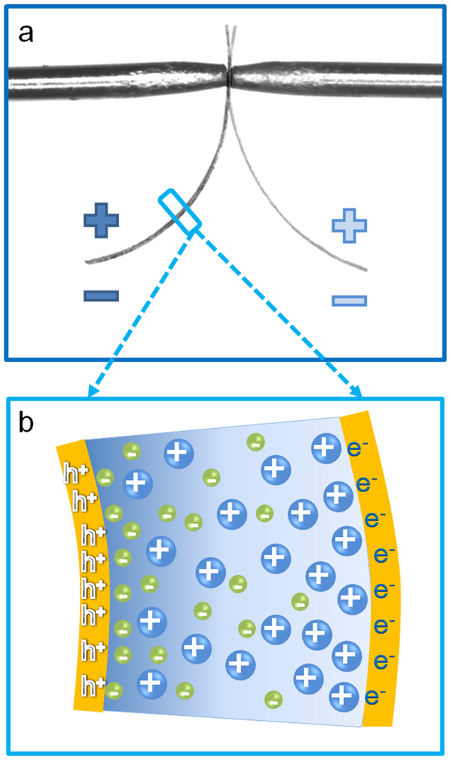
ToF-SIMS has recently been demonstrated as a powerful imaging tool for biomaterials17,18. Since ToF-SIMS with C60+ cluster ion beam allows etching organic materials without damaging their chemical integrity, the ion depth-profile information can be probed directly18,19,20,21,22,23,24. This unique feature makes it possible to study the electrode-electrolyte interaction in i-EAP actuators and other ionic based energy storage devices, such as supercapacitors and Li-polymer batteries. Utilizing this technique, we characterize the excess cation and anion profiles at both cathode and anode for an i-EAP actuator, consisting of Aquivion membrane with IL of 1-butyl-2,3-dimethylimidazolium chloride (BMMI-Cl) and planar electrodes. Such a Metal-Ionic conductor-Metal (MIM) structure, i.e., an ionic conductor with ILs sandwiched between two planar metal electrodes, is widely used as model systems to study ion transport and storage in ionic electroactive devices25,26,27. For the study here, Aquivion membrane with BMMI-Cl is selected which exhibits substantial bending actuation under applied voltage. Presented in Fig. 1(a) is a schematic of the bending actuation of an ionic electroactive polymer actuator containing ILs with different cation and anion sizes, resulting from the excess ion accumulation/depletion near the electrodes under applied voltage, as illustrated in Fig. 1(b).
Figure 1. Actuation mechanism of i-EAP actuators.
(a) Optical image of the bending actuation of the i-EAP actuator under AC electric signals. (b) Schematic of bending actuation mechanism.
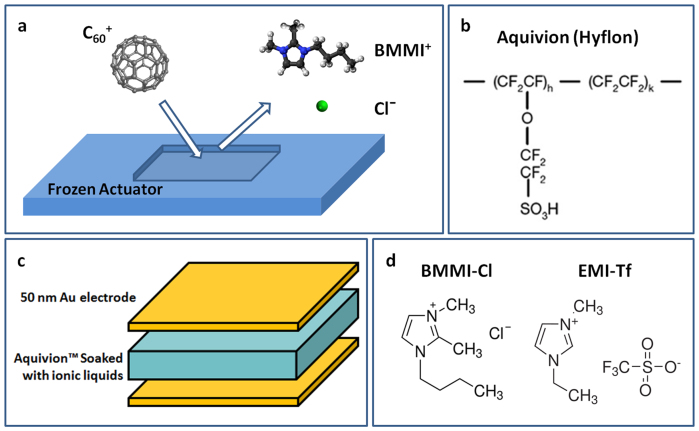
In this study, the excess ion accumulation/depletion profiles at the two electrodes established at high temperature (T > Tm; Tm = 99°C which is the melting temperature of pure IL) are rapidly frozen at dry ice temperature (T < −40°C), and bombarded with C60+ cluster ions at liquid nitrogen temperature (T ~−180°C) to extract the excess ion profiles of cations and anions near electrodes. The operation principle of ToF-SIMS is illustrated schematically in Fig. 2(a).
Figure 2. Operation mechanism and device configurations.
(a) Operation mechanism of ToF-SIMS for characterizing the depth profile of space charge regions near electrodes, (b) molecular structure of Aquivion, (c) device configuration, and (d) molecular structure of BMMI-Cl and EMI-Tf.
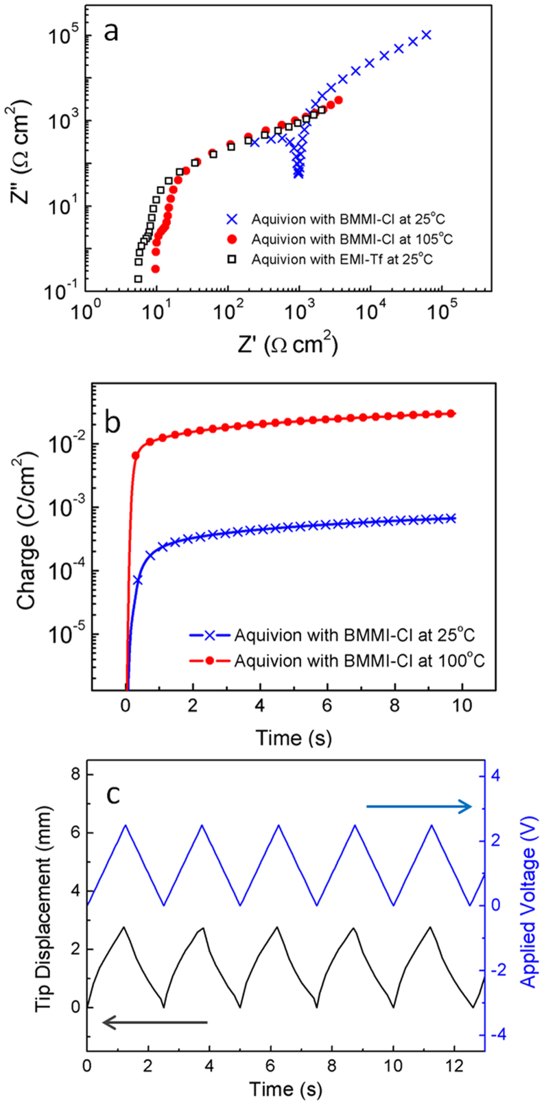
As shown in Fig. 2(b), Aquivion (Hyflon) is a Nafion-like perfluorosulfonate ionomer that consists of a Teflon backbone with shorter sulfonic acid side chains than Nafion15,28,29,30. Aquivion membrane with 45 wt% uptake of high temperature IL (or molten salt) BMMI-Cl (Fig. 2(d), melting point Tm = 99°C) is studied. The electroactive properties of the Aquivion/BMMI-Cl are compared to the same Aquivion with 45 wt% uptake of room temperature IL 1-ethyl-3-methylimidazolium trifluoromethanesulfonate (EMI-Tf) (Fig. 2(d) melting point Tm = −12°C), which has been studied earlier and exhibits a high actuation response15. High melting point of BMMI-Cl allows large temperature difference between the actuator operation temperature (T = 105°C) and the sample handling temperature before the ToF-SIMS experiment, which is in the range between −40°C and −78.5°C under dry ice cooling. Presented in Fig. 3(a) is the normalized Nyquist plot of two i-EAP membrane actuators, Aquivion/BMMI-Cl and Aquivion/EMI-Tf. The thicknesses of both samples are ~27 ± 2 μm. At 25°C, the Nyquist plot of Aquivion/BMMI-Cl, which is a foggy film from the electrolyte crystallization, shows a conductivity ~2.9 × 10⁻⁵ S/cm that is two orders of magnitude lower than that of Aquivion/EMI-Tf. After heating to 105°C so that the IL is in a liquid state (T > Tm), the electrical performance of Aquivion/BMMI-Cl becomes comparable to Aquivion/EMI-Tf. Earlier experimental studies on Aquivion/ILs i-EAPs indicate that there is a critical IL uptake in i-EAPs in order to generate large actuation, which is about 40 wt% for the Aquivion/IL i-EAPs. The large strain observed here indicates that 45 wt% BMMI-Cl in Aquivion is above the critical uptake and hence is chosen for the study.
Figure 3. Electrical and mechanical characterizations of Aquivion/BMMI-Cl actuators.
(a) Nyquist Plot of Aquivion/BMMI-Cl at 25°C (crosses) and 105°C (filled dots), compared to Aquivion/EMI-Tf at 25°C (open squares). (b) Charge versus time of Aquivion/BMMI-Cl at 25°C and 105°C under 2.5 V step voltage. (c) Bending actuation of Aquivion/BMMI-Cl at 105°C under AC stimulus.
Fig. 3(b) compares the charges accumulated vs. time under a step voltage of 2.5 V (which is higher than 25 mV used in acquiring the Nyquist plot) for the Aquivion/BMMI-Cl at 25°C and 105°C. Since the ionic conductivity decreases exponentially with temperature, the result indicates that by freezing the samples to −40°C after applying electrical field ions cannot migrate back to neutral state during the sample's transferring to the ToF-SIMS chamber (within 30 mins). Applied voltage (2.5 V for the data in Fig. 3(b) and 3(c), which is in the device operation or two electrodes configuration) is below the combined electrochemical window of the electrolytes which is about 3 V in the two electrode device configuration (see Supplementary information Fig. S3). The bending actuation of a 1 mm wide 6 mm long MIM actuator under 2.5 V triangular wave of 0.2 Hz at 105°C is presented in Fig. 3(c), which shows a peak-to-peak bending displacement of 2.9 mm and a corresponding bending curvature of 0.4 mm−1. This value is larger than the maximum bending magnitude of Aquivion/EMI-Tf measured at room temperature15. As will be shown by the ToF-SIMS data, this is likely caused by the large difference in the ion size between the cations and anions in BMMI-Cl compared with EMI-Tf31.
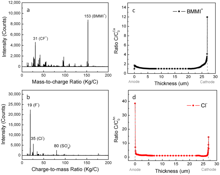
To perform ToF-SIMS experiment, the samples charged at 105°C in Fig. 3(b) were rapidly frozen under the applied voltage with dry ice to −40°C. The voltage was then removed and samples were processed at dry ice temperature (see Methods). Electric signals (voltage and current) were monitored in the sample quenching and transferring process and no electric signals related to charges flowing back to the neutral state or even excess ion redistribution were observed. The depth profile of ions characterized by ToF-SIMS with C60+ ions was then carried out at liquid nitrogen temperature (T~−180°C) on cathode and anode side of the sample. Data collections were repeated several times at liquid nitrogen temperature at different waiting times at −40°C and at liquid nitrogen temperatures and no difference was found, indicating that the ions were indeed frozen during the measurement. Typical mass spectra acquired for both positive ions and negative ions from Aquivion/BMMI-Cl actuator are displayed in Fig. 4(a) and 4(b), where the characteristic peaks of different components in the Aquivion/BMMI-Cl actuators can be distinguished. When bombarded with C60+ ions, BMMI+ and Cl− were easily extracted, while perfluorosulfonate polymer Aquavion was broken into fragments that mainly compose of C and F (S and O also present but less in quantity; molecular structures are displayed in Figure 2). Neat Aquivion ionomer without BMMI-Cl was also sputtered and checked to ensure no characteristic peaks from polymer fragments overlapping with peaks of BMMI+ or Cl−. From the mass-to-charge ratio in Fig. 4(a), peak at 31 accounts for polymer fragment CF+, and peak at 153 corresponds to the molecular ion of cation BMMI+, where the integrity of BMMI+ is preserved during C60+ sputtering. Similarly, in Fig. 4(b), peak at 35, 19, 80 are from the Cl− ion, fragment of the Teflon backbone of Aquivion (F−), and the sulfonic acid side chain of Aquivion (SO3−), respectively. These peaks were recorded for depth profile till ~7 μm from the surface where the BMMI+ or Cl− signal show flat profile. Sputtering times were converted into depth by measuring the corresponding depth of the craters and calculating the sputtering rate, which is 1.48 ± 0.15 nm/s. While depth profiles of mobile charge carriers BMMI+ and Cl− are intensively discussed in following paragraphs, F− and CF+, which are the major charged polymer fragments, was tracked and presented in Supplementary information Fig. S5.
Figure 4. ToF-SIMS spectra.
Mass spectra of (a) positive ions and (b) negative ions that are collected from Aquivion/BMMI-Cl actuators; depth profile of (c) cation and (d) anion concentrations. The ion concentration profiles in (c) and (d) are normalized to the plateau C0Ca region and the plateau C0An region, where C0Ca and C0An are the ion concentrations of cation and anion at the center of the membrane.
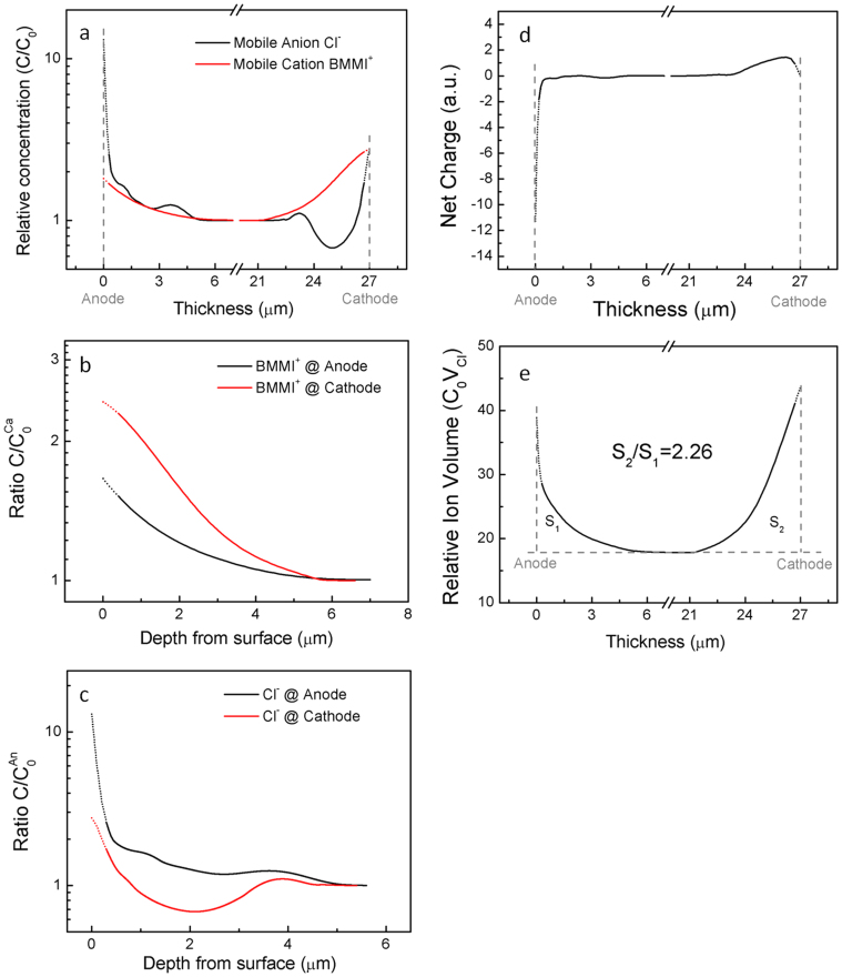
Under an applied voltage, mobile ions will redistribute near the electrodes to screen the external electric field. As a result, the charges stored on the actuator electrodes slowly approach saturation after charging at 2.5 V for several minutes, and the bulk of the ions in the middle of the membrane are not charged when the actuator approaches its steady state. Hence, in the Fig. 4 (c) and 4(d), the depth profiles of the relative concentrations of the cation and anion are displayed with respect to the counts from the plateau regions in the middle of the membrane. However, the first few points of each curve, which was collected from the polymer/gold interface, may have large experimental error due to the surface roughness (~170 nm), while the rest of the ion distribution is effectively preserved by the polymer matrix confinement. To provide visual aid for further discussions, the data in the surface roughness regions (d < 170 nm) are estimated by combining experimental data with fittings from the rest of the curves (d > 170 nm), and presented with dotted lines in Fig. 5(a)–(e).
Figure 5. Data analysis of ion depth profiles.
(a) Mobile cation and anion concentration with respect to the middle region in log scale. Due to the presence of negatively charged side groups in Aquivion, about 20% of cations in the entire systems are attached to the side groups, and hence are considered immobile. (b) Depth profile of cation and (c) depth profile of anion near electrodes in log scale to show details. Surface roughness regions (d ~ 170 nm) are fitted from the rest of the curves (d > 170 nm), and thus presented with doted lines (see Supplementary Information). (d) and (e) are net charge and relative ion volume through the entire actuator thickness.
Discussion
Presented in Fig. 5(a) are the relative ion concentrations through the entire film, where the data reveal that excess cations are present at both cathode and anode as are the anions. By further expanding the data in Fig. 5(a) in both axes, we compare the cation and anion distributions at cathode and anode in Fig. 5(b) and (c) in details. Although the excess cation concentration at the cathode is much higher (> 50% higher) than that at the anode, there are still a substantial amount of excess cations presents at anode. At both electrodes, the excess cation concentration decays monotonically with distance away from the electrodes, with characteristic lengths 1.83 μm (cathode) and 1.67 μm (anode) when fitting the curves with exponential decay functions. For anions, the data reveal quite interesting results: (i) Right near the cathode, there are high concentration excess anions. However, different from cations, the excess anion concentration becomes negative (anion deficiency) and also displays weak oscillation, which is much beyond the experimental error, till around 5 μm away from the cathode. (ii) At a narrow region near anode (d < 0.5 μm) there is a very high concentration of anions, which results in a higher capacitance at anode than that at cathode. The concentration of anions is always above the average and decays with the distance away from the anode. The decrease of the excess anion concentration with distance from the cathode is not monotonic and also exhibits oscillation. The results here show that the ion accumulation layers extend several μm beyond the electrode for the ionic liquid containing thin films, which are consistent with the observed large bending actuation of such a membrane actuator (Fig. 3(c)). Based on a five layer model developed earlier10 and assuming a differential strain of 20% between the two electrode regions (which is far larger than any reported values of intrinsic strain for ionic polymer actuators including ionic polymer metal composites10,11), the strain generation layer thickness which is caused by the excess ions is as thick as 1.5 μm (see Supplementary Information Fig. S6).
Furthermore, the excess ion accumulation/depletion depth directly observed here (Fig. 4 and Fig. 5) is also consistent with recent experimental studies of ionic devices with ILs15,32. Under a couple of volts, the charges accumulated due to ion diffusion, which is driven by the concentration gradient and occurs at time t ≫ ms, is orders of magnitudes higher than those from ion drifting (migration), which is driven by applied electric field and occurs at times t < ms15,32. It is these thick diffusion layers that lead to the significant bending of 27 μm thick film shown in Fig. 3(c). Therefore, our observations suggest that the diffusion layer is responsible for the micron range charge accumulation in ILs in i-EAP actuators (illustrated in Supplementary Information Fig. S7).
Presented in Fig. 5(d) is the net charge profiles at the two electrodes (integrated from Fig. 5 (b) and (c)) which show that the smaller size of anion results in a higher packing density of the charges near anode (large capacitance). The relative ion volumes (which is the volume occupied by excess ions) at cathode and anode are calculated and presented in Fig. 5(e). Cathode accommodates a larger volume of excess ions compared with anode, although both electrodes experience a positive strain (due to excess ions). The difference in the excess ion volumes between the two electrodes causes the bending actuation as illustrated in Fig. 1 and observed in Fig. 3(c). It should also be mentioned that for the Aquivion/BMMI-Cl membrane actuators studied here, there is no back relaxation (bending in reverse direction) of bending actuation which have been observed in many ionic polymer actuators using IL electrolytes with larger size anions such as EMI-Tf33. The back relaxation is not desirable for practical actuator applications34. The results here suggest an attractive approach to design ionic polymer actuators with ILs as electrolytes which have large ion size difference in order to eliminate the back relaxation.
In conclusion, the ion distribution of ILs under high voltage of an ionomer membrane (Aquivion) with IL (BMMI-Cl) electrolytes was characterized by ToF-SIMS. The results reveal that the ion accumulation/depletion regions extend several microns away from the electrodes and both cations and anions are present at each electrode. The small anions result in a narrow region (< 0.5 μm) high anion concentration at anode, causing a large capacitance and small voltage drop at anode. Right at the cathode, beside the high cation concentration, there is also a high anion concentration. Interestingly, away from the cathode, there is a large region of anion deficiency. As a result, the center of net position charge concentration profile is more than 1 μm away from the cathode. The asymmetric excess ion concentration profiles between the two electrodes are likely caused by the large difference in ion size between cation and anion, which also results in a large bending actuation without any back relaxation. The results here also demonstrate that ToF-SIMS is a powerful tool to directly characterize the carrier profiles in ionic energy storage and conversion devices, which provides great insights on the electroactive responses in these devices.
Methods
Sample preparation
Aquivion ionomer membrane (EW790, Solvay Solexis), BMMI-Cl (Aldrich) and EMI-Tf (Aldrich) were dried in vacuum at 80°C to remove moisture before processing. Aquivion membranes swollen with 45 wt% EMI-Tf were prepared by soaking the Aquivion membranes in EMI-Tf at 60°C. Aquivion membranes swollen with 45 wt% BMMI-Cl were prepared by soaking the Aquivion membranes in BMMI-Cl: Ethanol 1:1 solution at 60°C. The films are then dried again in vacuum oven at 60°C to remove ethanol. 50 nm thick of gold foils (L.A. Gold Leaf) were hot-pressed on both sides of the membranes as electrodes. The uptake of ILs within Aquivion membrane was calculated by measuring the weight gain after swelling. Density of the ionic liquid is calculated by weighing the ILs and measuring the volume with a graduated cylinder. Roughness of the sample surface is measured by Zygo NewView™ 7300 on an area of 140 μm × 110 μm.
Electrical and mechanical characterizations
The electrical measurement was carried out in a sealed box with desiccant inside to prevent the absorption of moisture. The box is then placed in an environmental chamber (Tenney Versa Tenn III) for temperature control, and the electrical characteristics are measured by a potentiostat (Princeton Applied Research 2273). The electromechanical response was recorded by using a probe station (Cascade Microtech M150) equipped with a Leica microscope and a CCD camera (Pulnix 6740CL). High temperature actuation was tested by placing sample and sample holder in a heat block (VWR) that is underneath the Leica microscope and the CCD camera.
TOF-SIMS
To collect the ion concentration data by ToF-SIMS, the actuator was firstly operated under 2.5 V bias at 105 ± 5°C for 5 minutes, till actuation reaches steady state. Then the sample box and actuator (still under voltage bias) were transferred into an isothermal bag and fast frozen with 5 lbs of dry ice. The temperature was measured with an infrared thermal meter and stabilized at −40°C in 20 ~ 30 minutes. Then the actuator 2 mm × 8 mm was taken out of the sample box with a plastic tweezers and placed on dry ice to section into two 2 mm × 2 mm pieces. Gold external electrodes were then carefully peeled off with Scotch tape from sample surfaces and the samples are mounted onto the sample holder for ToF-SIMs. The sample stage can be cooled to 100 K. After the actuator sample is loaded into the vacuum chamber of SIMS, it was cooled by liquid nitrogen and all depth profile experiments were run at liquid nitrogen temperature. A 40-keV C60 source (IOG 40–60, Ionoptika; Southampton, U.K.) is mounted to the instrument at an angle of 40° with respect to the surface normal. Under typical conditions, The kinetic energy of the singly charged C60+ primary ion beam is 40 keV and the beam current is 200 ~ 300 pA with a beam size of ~10 μm. The mass spectrometer was operated in a delayed extraction mode with 50 ns delay time between the primary ion pulse and the secondary ion extraction pulse. Charge compensation was found to be unnecessary due to a charge balance between primary and secondary ion currents. For depth profiling, the C60+ ion beam was operated in DC mode to erode through the film at an area of 340 μm × 440 μm. Between erosion cycles, SIMS images were acquired from the same area using the pulsed C60+ projectile beam with a total ion fluence below 1011 cm−2. A digital raster scheme with 256 × 256 pixels was employed during both the erosion and data acquisition cycles, which corresponds to a pixel step size (1–2 μm) well below the beam width. The ToF mass spectra were retrospectively extracted from various pixel areas of the image data in order to investigate crater edge effects and determine the optimum gating area as described elsewhere35. No edge effects were observed at the central area of 192 × 192 pixels inside the sputtered region, therefore mass spectra from these areas were used for depth profile analysis. Typical schematic of a ToF-SIMS instrument is provided in supplemental information. Eroded crater depths are characterized by KLA Tencor 16+ profilometer. The etching rate in this study is calculated from the etching depths and etching times.
Author Contributions
Y.L. and Q.M.Z. designed the experiments; Y.L. and S.T. prepared the samples and carried out the electrical characterizations, Y.L., C.L. and S.T. performed ToF-SIMS experiments; M.G. characterized the sample roughness; Y.L. and Q.M.Z. analyzed the results and prepared the manuscript. All authors discussed the results and commented on the manuscript at all stages.
Supplementary Material
Supplementary information
Acknowledgments
The authors thank Prof. Chun Liu, Prof. Ralph H. Colby and Mr. Kai Zhang for discussions regarding the work. This material is based upon work supported in part by NSF under the Grant No. CMMI 1130437, AFOSR Grant No.FA9550-11-1-0192, and the U.S. Army Research Office under Grant No. W911NF-07-1-0452 Ionic Liquids in Electro-Active Devices (ILEAD) MURI.
References
- Galinski M., Lewandowski A. & Stepniak I. Ionic liquids as electrolytes. Electrochimica Acta 51, 5567–5580 (2006). [Google Scholar]
- Armand M., Endres F., MacFarlane D. R., Ohno H. & Scrosati B. Ionic-liquid materials for the electrochemical challenges of the future. Nat Mater 8, 621–629 (2009). [DOI] [PubMed] [Google Scholar]
- Sakaebe H. & Matsumoto H. N-Methyl-N-propylpiperidinium bis(trifluoromethanesulfonyl)imide (PP 13-TFSI) - novel electrolyte base for Li battery. Electrochem Commun 5, 594–598 (2003). [Google Scholar]
- Garcia B., Lavallee S., Perron G., Michot C. & Armand M. Room temperature molten salts as lithium battery electrolyte. Electrochimica Acta 49, 4583–4588 (2004). [Google Scholar]
- Sato T., Masuda G. & Takagi K. Electrochemical properties of novel ionic liquids for electric double layer capacitor applications. Electrochimica Acta 49, 3603–3611 (2004). [Google Scholar]
- Largeot C. et al. Relation between the ion size and pore size for an electric double-layer capacitor. J Am Chem Soc 130, 2730–+ (2008). [DOI] [PubMed] [Google Scholar]
- de Souza R. F., Padilha J. C., Goncalves R. S. & Dupont J. Room temperature dialkylimidazolium ionic liquid-based fuel cells. Electrochem Commun 5, 728–731 (2003). [Google Scholar]
- Lu W. et al. Use of ionic liquids for pi-conjugated polymer electrochemical devices. Science 297, 983–987 (2002). [DOI] [PubMed] [Google Scholar]
- Bennett M. D. & Leo D. J. Ionic liquids as stable solvents for ionic polymer transducers. Sensors and Actuators a-Physical 115, 79–90 (2004). [Google Scholar]
- Liu S. et al. Layer-by-layer self-assembled conductor network composites in ionic polymer metal composite actuators with high strain response. Applied Physics Letters 95, – (2009). [Google Scholar]
- Liu S. et al. High Electromechanical Response of Ionic Polymer Actuators with Controlled-Morphology Aligned Carbon Nanotube/Nafion Nanocomposite Electrodes. Adv Funct Mater 20, 3266–3271 (2010). [DOI] [PMC free article] [PubMed] [Google Scholar]
- Mezger M. et al. Molecular layering of fluorinated ionic liquids at a charged sapphire (0001) surface. Science 322, 424–428 (2008). [DOI] [PubMed] [Google Scholar]
- Endres F., Borisenko N., El Abedin S. Z., Hayes R. & Atkin R. The interface ionic liquid(s)/electrode(s): In situ STM and AFM measurements. Faraday Discuss 154, 221–233 (2012). [DOI] [PubMed] [Google Scholar]
- Hayes R. et al. Double Layer Structure of Ionic Liquids at the Au(111) Electrode Interface: An Atomic Force Microscopy Investigation. Journal of Physical Chemistry C 115, 6855–6863 (2011). [Google Scholar]
- Lin J. H., Liu Y. & Zhang Q. M. Charge dynamics and bending actuation in Aquivion membrane swelled with ionic liquids. Polymer 52, 540–546 (2011). [DOI] [PMC free article] [PubMed] [Google Scholar]
- Liu Y. et al. Enhanced Electromechanical Response of Ionic Polymer Actuators by Improving Mechanical Coupling between Ions and Polymer Matrix. Macromolecules 45, 5128–5133 (2012). [Google Scholar]
- Ostrowski S. G., Van Bell C. T., Winograd N. & Ewing A. G. Mass spectrometric imaging of highly curved membranes during Tetrahymena mating. Science 305, 71–73 (2004). [DOI] [PMC free article] [PubMed] [Google Scholar]
- Winograd N. The magic of cluster SIMS. Anal Chem 77, 142a–149a (2005). [Google Scholar]
- Wagner M. S. Molecular depth profiling of multilayer polymer films using time-of-flight secondary ion mass spectrometry. Anal Chem 77, 911–922 (2005). [DOI] [PubMed] [Google Scholar]
- Mahoney C. M., Roberson S. V. & Gillen G. Depth profiling of 4-acetamindophenol-doped poly(lactic acid) films using cluster secondary ion mass spectrometry. Anal Chem 76, 3199–3207 (2004). [DOI] [PubMed] [Google Scholar]
- Cheng J. & Winograd N. Depth profiling of peptide films with TOF-SIMS and a C-60 probe. Anal Chem 77, 3651–3659 (2005). [DOI] [PubMed] [Google Scholar]
- Sostarecz A. G., Sun S., Szakal C., Wucher A. & Winograd N. Depth profiling studies of multilayer films with a C-60(+) ion source. Appl Surf Sci 231, 179–182 (2004). [Google Scholar]
- McQuaw C. M., Sostarecz A. G., Zheng L. L., Ewing A. G. & Winograd N. Lateral heterogeneity of dipalmitoylphosphatidylethanolamine-cholesterol Langmuir-Blodgett films investigated with imaging time-of-flight secondary ion mass spectrometry and atomic force microscopy. Langmuir 21, 807–813 (2005). [DOI] [PubMed] [Google Scholar]
- Kozole J., Wucher A. & Winograd N. Energy deposition during molecular depth profiling experiments with cluster ion beams. Anal Chem 80, 5293–5301 (2008). [DOI] [PMC free article] [PubMed] [Google Scholar]
- Bazant M. Z., Storey B. D. & Kornyshev A. A. Double Layer in Ionic Liquids: Overscreening versus Crowding. Phys Rev Lett 106 (2011). [DOI] [PubMed] [Google Scholar]
- Zhao H. Diffuse-charge dynamics of ionic liquids in electrochemical systems. Physical Review E 84 (2011). [DOI] [PubMed] [Google Scholar]
- Li J., Park J. K., Moore R. B. & Madsen L. A. Linear coupling of alignment with transport in a polymer electrolyte membrane. Nat Mater 10, 507–511 (2011). [DOI] [PubMed] [Google Scholar]
- Mauritz K. A. & Moore R. B. State of understanding of Nafion. Chemical Reviews 104, 4535–4585 (2004). [DOI] [PubMed] [Google Scholar]
- Arcella V., Troglia C. & Ghielmi A. Hyflon ion membranes for fuel cells. Ind Eng Chem Res 44, 7646–7651 (2005). [Google Scholar]
- Kreuer K. D. et al. Short-side-chain proton conducting perfluorosulfonic acid ionomers: Why they perform better in PEM fuel cells. Journal of Power Sources 178, 499–509 (2008). [Google Scholar]
- Liu S. et al. Influence of imidazolium-based ionic liquids on the performance of ionic polymer conductor network composite actuators. Polymer International 59, 321–328 (2010). [Google Scholar]
- Bazant M. Z., Thornton K. & Ajdari A. Diffuse-charge dynamics in electrochemical systems. Physical Review E 70 (2004). [DOI] [PubMed] [Google Scholar]
- Liu Y. et al. Ion transport and storage of ionic liquids in ionic polymer conductor network composites. Applied Physics Letters 96 (2010). [Google Scholar]
- Bar-Cohen Y. Electroactive polymers as artificial muscles: A review. J Spacecraft Rockets 39, 822–827 (2002). [Google Scholar]
- Zheng L. L., Wucher A. & Winograd N. Retrospective sputter depth profiling using 3D mass spectral imaging. Surf Interface Anal 43, 41–44 (2011). [DOI] [PMC free article] [PubMed] [Google Scholar]
Associated Data
This section collects any data citations, data availability statements, or supplementary materials included in this article.
Supplementary Materials
Supplementary information


