Abstract
Filopodia are long, thin protrusions formed when bundles of fibers grow outwardly from a cell surface while remaining closed in a membrane tube. We study the subtle issue of the mechanical stability of such filopodia and how this depends on the deformation of the membrane that arises when the fiber bundle adopts a helical configuration. We calculate the ground state conformation of such filopodia, taking into account the steric interaction between the membrane and the enclosed semiflexible fiber bundle. For typical filopodia we find that a minimum number of fibers is required for filopodium stability. Our calculation elucidates how experimentally observed filopodia can obviate the classical Euler buckling condition and remain stable up to several tens of  . We briefly discuss how experimental observation of the results obtained in this work for the helical-like deformations of enclosing membrane tubes in filopodia could possibly be observed in the acrosomal reactions of the sea cucumber Thyone, and the horseshoe crab Limulus. Any realistic future theories for filopodium stability are likely to rely on an accurate treatment of such steric effects, as analysed in this work.
Introduction
Filopodia are formed by the growth of bundles of biological fibers outwards from a biological cell surface that remain enclosed in a membrane tube. They are implicated in many processes vital to life, including sensing and motility [1] [2] [3]. There has therefore been much interest recently in the formation and growth of long, thin cellular protrusions due to the polymerization of bundles of fibers, including actin [4]. Such structures appear on cell membranes as familiar filopodia [1] [4], but can also appear on neural growth cones [5], sickled red blood cells [6] [7], the acrosomal reaction of the sea cucumber Thyone [8] [9], as well as on vesicles observed in vitro [10].
In this work, we investigate the stability of filopodia, which involves the subtle interplay between a fluid membrane tube, and an enclosed semiflexible fiber bundle. The simplest physical picture of filopodia is one in which the membrane tube produces a longitudinal force and a transverse force on the enclosed fiber bundle. The longitudinal membrane force acts to try and shorten the end-to-end distance of the fiber bundle, while the transverse force is required to maintain fiber bundle enclosure. The energetics required to investigate the stability of filopodia thus necessitates us to consider the elasticity of both the membrane tube as well as the fiber bundle, subject to the constraint that the polymer bundle must remain enclosed by the membrane tube. The energetic ground state conformations of filopodia thus necessitate a careful theoretical treatment of both elastic and steric considerations. For example, one might ask if a filopodium ever buckles, or perhaps more intriguingly does the region of filopodium buckling exist in some small corner of a complicated energetic phase diagram, well outside the range of physiologically relevant parameters?
A naive Euler buckling type estimate for the stability of filopodia [11]
[12] suggests a limiting length of  . Additionally, the presence of cross-linking in the fiber bundle, and hence increased stiffness, further suggest a limiting length of
  for stable filopodia [11]
[12]. However, filopodia many tens of
  have been observed experimentally [8]
[13].
In [11], a helical ansatz was employed for the conformation of the polymer bundle. However, for analytical calculational purposes this was assumed to reside inside an enclosing membrane tube that remained perfectly cylindrical, despite simulation snapshot evidence to the contrary [11]. Energetically stable ground state configurations were calculated for filopodia within the range of physiologically relevant parameters. However, due to the presence of very soft modes [14] for membrane tube deformations, it is unrealistic to analytically assume that the enclosing membrane tube will remain perfectly cylindrical. It would cost the membrane tube very little energy to deform in order to accommodate the enclosed helical fiber bundle (see Fig. 1). In order to calculate analytically the ground state configurations of realistic filopodia, and their corresponding energetic stability, we find that it is necessary to explicitly compute the conformation of the enclosing membrane tube. This is achieved by minimising a rigorously derived energy functional (defined below) that includes the elastic response of both the membrane and the fiber bundle while respecting the constraint that the helical polymer bundle must remain enclosed by the membrane tube.
Figure 1. Sketch of a helically deformed membrane enclosing a helical fiber bundle.

The membrane radius is given by  , the helical polymer radius is given by
  , and
, and  is the radial size of the enclosed polymer filament bundle.
Results
Typical experimental parameter values for biological membranes range from [2]
[15]
 ,
,  . In order to compare the results of this work with that of [11], we take
  and
and  throughout in what follows. These values gives rise to a typical membrane tube radius of
  . In order to estimate the radial size
  of a filament bundle, we consider a cross-section of
  fibers each with a typical size
  , which we assume forms a hexagonally close packed structure [9]. A suitable continuum approximation for the bundle radius
  as a function of the number of fibers
  is then :
  , which approximates to
  , for
, for  . If we take
  (for actin filaments), and
  , then typical biological fiber bundles possess radii
  . Thus we can see that the finite radius filament bundle considerations contained in this work become important for physiological filopodia.
The ground-state configuration of a filopodium is determined by finding the minimum of the total energy per unit length  of Eq. (12) as given below. The relevant two parameters we need to minimise over are the
  extension factor
  , and the helical radius of the enclosed fiber bundle
  , while keeping the number of fibers
  fixed.
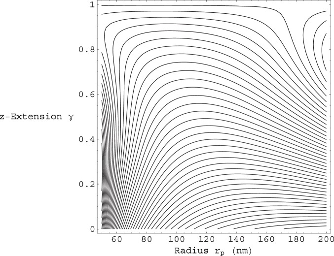
Shown in Fig. 2 is the contour plot of the total energy per unit contour length  from Eq.(12). for a single fiber
  . The energy is plotted as a function of the enclosed filament helical radius
  , and the
  extension factor
  . It can be seen from Fig. 2 that, for the
  and
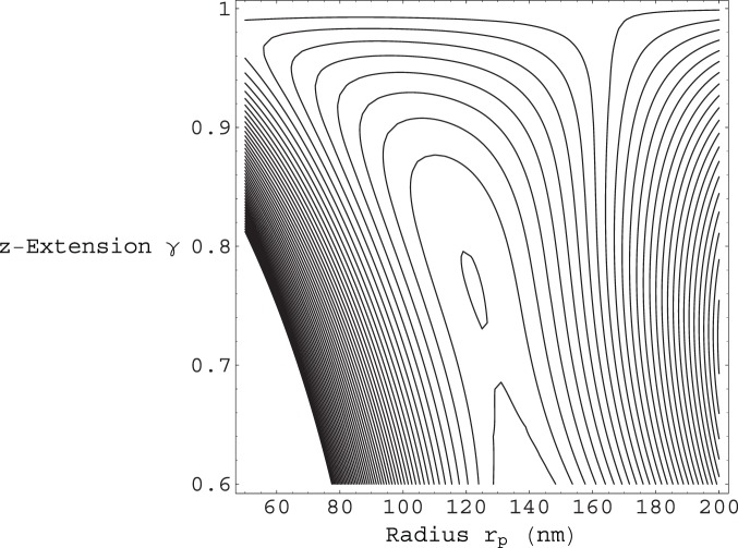
and  values used, a single fiber does not give rise to a local energy minimum, and is therefore unstable. We find that the minimum number of fibers required for filopodium stability is given by
  , as shown in Fig. 3, which gives rise to a local energy minimum at:
  and
and  , corresponding to one helical winding per
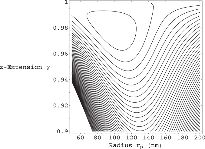
  of contour length. From Fig. 4 we can see that for
  we have a local energy minimum at:
  and
and  , corresponding to one helical winding per
  of contour length. Moreover, form Fig. 5 we can see that as the number of fibers
  in a bundle increases, our filopodium remains stable, with the
  extension factor rapidly approaching the maximum allowed value of
  . Furthermore, as
  increases, we can see from Fig. 6 that
  decreases, tending towards the limiting value of
  , as the number of fibers becomes large. Additionally, we can see from Fig. 7 that the amount of helical winding required for stability reduces concomitantly also, as the number of fibers in a bundle
  increases.
Figure 2. Contour plot of the total energy per unit contour length  from Eq.(12).
The energy is plotted as a function of the enclosed filament helical radius  , and the
  extension factor
  . The membrane bending modulus is
  and the surface tension is
  . The same values of
  and
and  are used in all subsequent figures. The number of filaments in this case is given by
  . These parameters do not give rise to a local energy minimum. The contours near the top of the plot have values around
  , those contours near the middle
  , and the nearest to bottom contours on the plot
  , (at room temperature).
Figure 3. Contour plot of the total energy per unit contour length  from Eq.(12).
The energy is plotted as a function of the enclosed filament helical radius  , and the
  extension factor
  . The number of filaments in this case is given by
  . These parameters give rise to a local energy minimum at:
  and
and  , corresponding to one helical winding per
  of contour length. Both the contours near the top and bottom of the plot have values around
  , while the closed contour near the middle has a value of
  .
.
Figure 4. Contour plot of the total energy per unit contour length  from Eq.(12).
The energy is plotted as a function of the enclosed filament helical radius  , and the
  extension factor
  . The number of filaments in this case is given by
  . These parameters give rise to a local energy minimum at:
  and
and  , corresponding to one helical winding per
  of contour length. The closed contour near the top of the plot has a value of
  , while the contours close to the bottom of the plot have values
  .
.
Figure 5. Plot of the extension factor  along the
  axis versus the number of filaments
  .
.
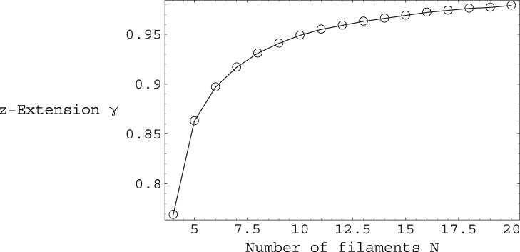
The  values plotted correspond to the energetic minima of the total energy per unit contour length
  from Eq.(12), for a given number of filaments
  .
.
Figure 6. Plot of the polymer helical radius  versus the number of filaments
  .
.
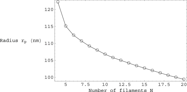
The  values plotted correspond to the energetic minima of the total energy per unit contour length
  from Eq.(12), for a given number of filaments
  . For comparison, note that
  .
.
Figure 7. Plot of the polymer helical winding length versus the number of filaments  .
.
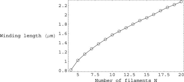
The winding length values plotted correspond to the polymer contour length required for one complete helical turn in order to maintain stability of the filopodium.
Discussion
We have calculated theoretically the ground state configurations of filopodia, and found ‘islands of stability’ for typical filopodia within physiologically relevant parameters. Our calculation elucidates how experimentally observed filopodia can obviate the classical Euler buckling condition and remain stable up to several tens of  [1]
[8]
[13]. We find, as in [11] that the enclosing membrane tube tends to stabilise filopodia, rather than de-stabilise as a naive Euler buckling estimate might suggest.
The work presented here differs from that presented in [11] in the following, important ways. Firstly, we correctly incorporate the effects of a finite fiber bundle radial size  , in this work, which was absent in [11]. Secondly, the total energy
  given by Eq.(12) of this work is calculated rigorously and analytically, taking into proper account the steric constraint of membrane tube enclosure of our semiflexible fiber bundle. The presence of soft modes for membrane tube deformations, implies that the membrane tube typically deforms in order to accommodate the enclosed helical fiber bundle, and does not remain perfectly straight, as analytically assumed in [11]. Thirdly, as we have found, there exists a delicate interplay between a fluid membrane tube and an enclosed semiflexible fiber bundle in filopodia. It is therefore imperative that the most accurate and correct total energy function for filopodia be calculated, as achieved in this work. Only then does it become possible to realistically describe the rather subtle issue of whether a given filopodium exists in a stable or a collapsed state. For example, we find in this work that the minimum number of fibers required for stability is given by
  , whereas in [11] all fibers with
  are deemed unstable.
Experimental observation of the results obtained in this work for the helical-like deformations of enclosing membrane tubes in filopodia would presumably be difficult. However, such helical membrane conformations are qualitatively supported by the snapshot pictures of simulation work carried out in [11], and could possibly be observed in the acrosomal reactions of the sea cucumber Thyone [8], and the horseshoe crab Limulus [16].
We adopt a ground state approximation in which thermal fluctuations are assumed to be small. Since the amplitude of these fluctuations is small at the high tensions of interest to us here, perhaps a few nm or less [17], this is a reasonable approximation.
Analogous steric constraints to those considered here are likely to be of relevance in other similar and important biological contexts, such as the packaging of semiflexible DNA in viral capsids, for example [18] [19] [20]. The interesting issue of mechanical stability in biological cellular tubes without an enclosed stiff polymer has also recently been considered in [21].
Models
Polymer Energy
In order to describe the filament bundle, inside filopodia, we study the semi-flexible polymer Hamiltonian  (where we chose energy units such that
  throughout):
| (1) |
with  .
.  is the contour length of the fiber bundle, and we take the persistence length for un-crosslinked bundles of
  fibers to be
  [12], where
  is the bending modulus of a single fiber (
 for actin [2]).
Any realistic deformation of the polymer must be able to pack a given contour length  within a given radius and extension along the
  axis, as prescribed by the enclosing membrane tube. We therefore assume the most plausible conformation for the polymer as being that of a helix, as also outlined in [11].
| (2) |
We have chosen to parameterise the polymer in terms of the  coordinate, as opposed to the arc-length
  , in order to simplify consideration of the required steric constraint between the polymer and the membrane as outlined below. Inextensibility for the polymer is maintained by requiring that:
 |
(3) |
In this way we can easily translate between the arc-length  , and
, and  extension representations, by defining:
  and
and  , such that:
  .
.
The polymer part  is thus straightforwardly calculated to be:
| (4) |
Membrane Energy
In order to describe deformations of our membrane tube, we use:
| (5) |
where  is the usual Hamiltonian for membrane elasticity [22]
[23], containing both surface tension (
 ) and rigidity (
 ) controlled terms.
We parameterise our membrane given by  in the usual way as:
| (6) |
The membrane contribution  is calculated as follows. We proceed by writing perturbatively:
  , which involves the radial length scale
  . In this way we obtain:
| (7) |
where the kernel  is given by:
  .
.
Steric Constraint
By inspection of Eqs. (2) and (6), we can see that the steric condition we need to apply to the membrane in order to guarantee polymer enclosure is given by:
| (8) |
where  is the radial size of the polymer filament bundle. By writing perturbatively:
  , the steric constraint of Eq. (8) now implies:
  . We enforce this steric constraint by introducing the following Hamiltonian
  :
:
| (9) |
which includes a Lagrange multiplier  that ensures membrane tube enclosure of the confined polymer helix. While the steric relationship is strictly an inequality, on physical grounds the ground state polymer configuration always tends to contact the membrane because the longer the polymer the smaller the compressive load it can support before it buckles, becoming helical. Thus a long polymer will always tend to adopt a helical configuration, stabilised by the inward-pointing membrane force, at the maximum radius allowed by the steric constraint.
Total Energy
In order to find the ground-state configuration of our filopodium, we need to find the conformation which minimises the total energy  given by:
  . By varying
  w.r.t.
  and
and  , and by using the relevant Green functions, we obtain:
| (10) |
along with  , and where the Fourier coefficients
  are given by:
  . Note that an ansatz loosely similar to Eq. (10) was also used in [24] to minimise the energy for a stack of
  cylindrical membranes, in order to describe the helical coiling behaviour of myelin tubes. Indeed, the filopodia described in this work, consisting of a fiber bundle of radius
  enclosed by a membrane tube, can analogously be thought of as an ‘
 ’ cylindrical membrane stack. In terms of the Fourier coefficients
  , the membrane radius solution of Eq. (10) can additionally be seen to automatically satisfy the steric constraint:
  .
.
Putting the result of Eq. (10) into  we get (valid to quadratic order in
  ):
):
| (11) |
By inspection of the Fourier coefficients  , it can be seen that for small
  winding the leading order contribution to
  comes from the
  mode, and is proportional to
  . This leads to a relatively weak strength for the quadratic potential in
  , and is due to the fact that the
  ,
,  mode is an extremely soft mode for membrane tubes as shown in [14]. Indeed, the
  ,
,  mode corresponds precisely to a rigid translation of the entire tube, and cannot therefore make any contribution to the membrane energy
  . It can also be shown that the modes that contribute to
  to next to leading order are the
  mode corresponding to a uniform dilation of the membrane tube, and the
  mode, which corresponds to a small deformation of the cross-section of our tube from a circular shape to that of an ellipse.
Utilising the inextensibilty conditions outlined above, we can easily re-write  in terms of the contour length
  , and the
  extension factor
  . In particular we find for the winding rate
  , to leading order. We thus arrive at our final expression for the total energy per unit length of a filopodium as (valid to quadratic order in
  ):
):
| (12) |
where the Fourier coefficients  are now functions of
  . The ground-state configuration of our filopodium can now be determined by minimising the total energy per unit length
  of Eq. (12), with respect to the two parameters
  (the
(the  extension factor) and
  (the helical radius of the enclosed fiber bundle).
Acknowledgments
We would like to thank the anonymous referees for their helpful comments.
Funding Statement
These authors have no support or funding to report.
References
- 1.Alberts B, Johnson A, Lewis J, Raff M, Roberst K, et al.. (2002) Molecular Biology of the Cell. New York: Garland.
- 2.Boal D (2001) Mechanics of the Cell. Cambridge: Cambridge University Press.
- 3.Bray D (1992) Cell Movements. New York: Garland.
- 4. Mattila PK, Lappalainen P (2008) Filopodia: molecular architecture and cellular functions. Nat Rev Mol Cell Biol 9: 446–454. [DOI] [PubMed] [Google Scholar]
- 5. Mitchison T, Kirschner M (1988) Cytoskeletal dynamics and nerve growth. Neuron 1: 761–772. [DOI] [PubMed] [Google Scholar]
- 6. Briehl RW (1995) Nucleation, fiber growth and melting, and domain formation and structure in sickle cell hemoglobin gels. J Mol Biol 245: 710–723. [DOI] [PubMed] [Google Scholar]
- 7. Daniels DR, Turner MS (2004) The force generated by biological membranes on a polymer rod and its response: Statics and dynamics. J Chem Phys 121: 7401–7407. [DOI] [PubMed] [Google Scholar]
- 8. Tilney LG, Inoue S (1982) Acrosomal reaction of thyone sperm. ii. the kinetics and possible mech-anism of acrosomal process elongation. J Cell Biol 93: 820–827. [DOI] [PMC free article] [PubMed] [Google Scholar]
- 9. Daniels DR (2010) Effect of capping protein on a growing filopodium. Biophys J 98: 1139–1148. [DOI] [PMC free article] [PubMed] [Google Scholar]
- 10. Fygenson DK, Marko JF, Libchaber A (1997) Mechanics of microtubule-based membrane extension. Phys Rev Lett 79: 4497–4500. [Google Scholar]
- 11. Pronk S, Geissler PL, Fletcher DA (2008) Limits of filopodium stability. Phys Rev Lett 100: 258102. [DOI] [PMC free article] [PubMed] [Google Scholar]
- 12. Mogilner A, Rubinstein B (2005) The physics of filopodial protrusion. Biophys J 89: 782–795. [DOI] [PMC free article] [PubMed] [Google Scholar]
- 13. Wood W, Martin P (2002) Structures in focus - filopodia. Int J Biochem Cell Biol 34: 726–730. [DOI] [PubMed] [Google Scholar]
- 14. Fournier JB, Galatola P (2007) Critical fluctuations of tense fluid membrane tubules. Phys Rev Lett 98: 018103. [DOI] [PubMed] [Google Scholar]
- 15. Derenyi I, Julicher F, Prost J (2002) Formation and interaction of membrane tubes. Phys Rev Lett 88: 238101. [DOI] [PubMed] [Google Scholar]
- 16. DeRosier DJ, Tilney L, Flicker P (1980) A change in the twist of the actin containing filaments occurs during the extension of the acrosomal process in limulus sperm. J Mol Biol 137: 375–389. [DOI] [PubMed] [Google Scholar]
- 17. Daniels DR, Turner MS (2005) Spicules and the effect of rigid rods on enclosing membrane tubes. Phys Rev Lett 95: 238101. [DOI] [PubMed] [Google Scholar]
- 18. Marenduzzo D, Micheletti C, Orlandini E (2010) Biopolymer organization upon confinement. J Phys - Cond Mat 22: 283102. [DOI] [PubMed] [Google Scholar]
- 19. Morrison G, Thirumalai D (2009) Semiflexible chains in confined spaces. Phys Rev E 79: 011924. [DOI] [PubMed] [Google Scholar]
- 20. Hu Y, Zandi R, Anavitarte A, Knobler CM, Gelbart WM (2008) Packaging of a polymer by a viral capsid: The interplay between polymer length and capsid size. Biophys J 94: 1428–1436. [DOI] [PMC free article] [PubMed] [Google Scholar]
- 21. Hannezo E, Prost J, Joanny JF (2012) Mechanical instabilities of biological tubes. Phys Rev Lett 109: 018101. [DOI] [PubMed] [Google Scholar]
- 22.Safran SA (1994) Statistical Thermodynamics of Surfaces Interfaces and Membranes. Boston, MA: Addison Wesley Publishing.
- 23.Nelson D (1989) in Statistical Mechanics of Membranes and Surfaces. Singapore: World Scientific.
- 24. Santangelo CD, Pincus P (2002) Coiling instabilities of multilamellar tubes. Phys Rev E 66: 061501. [DOI] [PubMed] [Google Scholar]


