Abstract
A carbon nanotube (CNT) integrated polymer composite membrane with a polyvinyl alcohol barrier layer has been prepared to separate oil from water for treatment of oil-containing waste water. The CNTs were synthesised using chemical vapour deposition, and a phase inversion method was employed for the blending of the CNTs in the polymer composite solution for casting of the membrane. Relative to the baseline polymer, an increase of 119% in the tensile strength, 77% in the Young's modulus and 258% in the toughness is seen for a concentration of 7.5% CNTs in the polymer composite. The permeate through the membrane shows oil concentrations below the acceptable 10 mg/L limit with an excellent throughput and oil rejection of over 95%.
High volumes of wastewater in the form of oil-water emulsion are produced in various industries such as oil fields, petrochemical, metallurgical, pharmaceutical and others1. Oil concentrations in wastewater generated in the above industries2 range from 50–1000 mg/L however, the acceptable discharge limit3 is only 10–15 mg/L. Membrane filtration has been established as a widely used method for water purification, and various filtration techniques are differentiated by the minimum size of the suspended particles they can separate, namely microfiltration (0.1–10 μm), ultrafiltration (0.01–0.10 μm), nanofiltration (order of nanometers), and reverse osmosis which can remove mono-ionic salts in solution. Microfiltration4, ultrafiltration5, nanofiltration and reverse osmosis6 have all been successfully used in the separation of oil from water. These techniques are useful because of the high quality water produced, simpler module design, low amount of chemicals used and low energy consumption compared to other treatment techniques7. Although the aforementioned techniques are attractive, they are not without problems.
The two major problems with membrane filtration are fouling and concentration polarization. Fouling is the accumulation of substances on the surface and/or inside the membrane pores, thereby decreasing the performance of the membrane8,9,10. Membrane fouling may occur due to the following reasons11: (i) biological fouling which is the growth of biological species on the membrane surface, (ii) colloidal fouling which leads to a loss of permeate flux through the membrane, (iii) organic fouling due to the deposition of organic substances, and (iv) scaling, defined as the formation of mineral deposits precipitating from the feed stream to the membrane surface. A total control of fouling is ideal to reduce the need for cleaning and enhance the permeate yield12,13. When a mixture is in contact with the membrane, the components in the mixture permeate at different rates. Concentration polarization is when the components that permeate slowly or not at all accumulate and create a layer near the membrane surface.
Suitable modification of the membrane is probably the most sustainable approach to obtain fouling-resistant membranes14. This would require the insertion of hydrophilic groups into a polymeric structure, so that the overall material becomes more hydrophilic and thus less prone to (organic) fouling13. Poly (vinyl alcohol) (PVA), which is a water-soluble biodegradable polymer available with different degrees of hydrolysis, is an ideal candidate for this purpose due to its hydrophilicity and film forming characteristics15,16,17. Commonly, membrane selectivity can be increased through the modification of the chemical structure of the polymer by cross-linking and grafting18,19.
Here we discuss the fabrication and testing of a carbon nanotube (CNT)-infused polymer composite membrane with PVA as a barrier layer and demonstrate the effectiveness of the membrane in rejecting oil from waste water. CNTs exhibit many desirable mechanical, thermal and other properties for a variety of applications20. Several studies have shown successful transferring of thermal21, electrical22 and mechanical23 properties of CNTs to polymer composites. PVA has been used as barrier layer composite membrane17 to remove NaCl (22.8% rejection) and MgSO4 (83.8% rejection) from solution. Here, we seek to show that CNTs infused with a polymer composite membrane (using PVA as a barrier layer) are able to increase the mechanical strength of the membrane whilst still remaining highly effective for oil-water separation.
Results
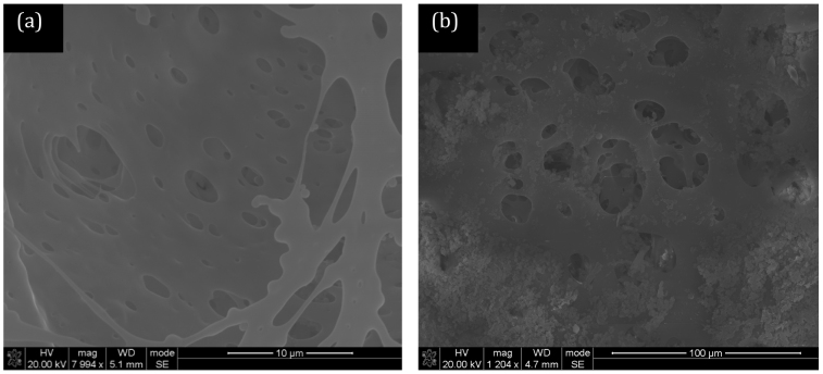
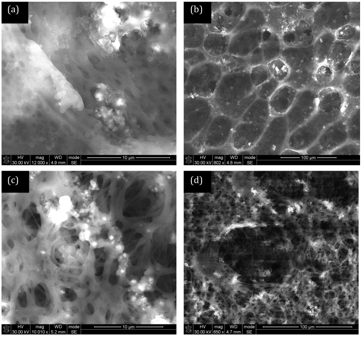
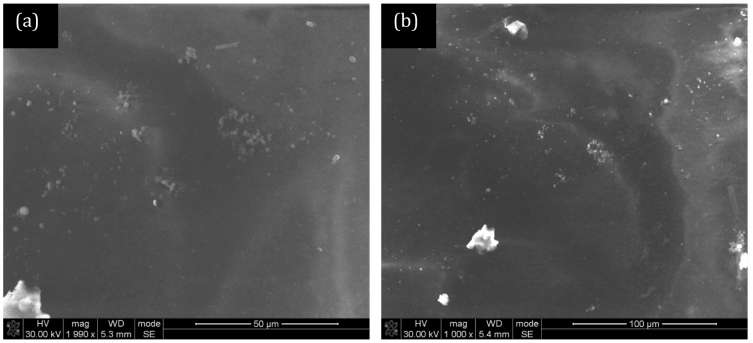
The CNTs used in this study were synthesised at 850°C using a previously-described bulk production process and ranged between 500 nm and 1000 nm in length24,25. The concentric arrangement of the graphene sheets parallel to the tube axis, which is typical for a multi-walled tube structure, is confirmed in transmission electron microscopy (TEM) images presented in our previous publications24,25. The diameter distribution of the as-produced CNTs is uniform with diameters less than 100 nm observed. A close analysis of TEM images reveals representative multiwalled-CNTs with inner diameters of 6.2–7.9 nm and outer diameters of 26.2–32.1 nm. As the CNTs were not purified or subjected to acid treatement before utilisation, there was no introduction of any functional groups on the surface of the CNTs. Figure 1 shows scanning electron microscopy (SEM) images of the bottom (Polysulfone, PSF) layer of the membrane. This layer is highly porous with the visible pores being less than 10 microns. This particular layer contains no CNTs for comparison purposes. Figure 2 shows the bottom (PSF) layer of the membrane with 5% and 10% CNTs in the polymer solution. The structure of this layer appears to change with the addition of CNTs. The pores in the membrane for the 10% CNT case appear to be more numerous and more finely dispersed than at lower concentrations. BET (Brunauer-Emmett-Teller) analysis gives the average adsorption pore width as 18.9 nm at 0% CNT, 27.6 nm at 5% CNT and 31.8 nm at 10%. Figure 3 shows the PVA layer on top of the bottom (PSF) porous layer indicating no clearly visible pores on the SEM images.
Figure 1. SEM image of a polysulfone (PSF) membrane (a) low and (b) high magnification without CNTs.
BET analysis gives the average adsorption pore size as 18.9 nm.
Figure 2. PSF membranes with 5% CNT (w/w) loading (a) low and (b) high magnification, PSF membranes with 10% CNT (w/w) loading (c) low and (d) high magnification.
BET analysis gives the average adsorption pore size of 27.6 nm for 5% CNT loading and 31.8 nm for 10% CNT loading.
Figure 3. SEM image of the polyvinyl alcohol (PVA) thin layer on base (PSF) membrane (a) low and (b) high magnification.
No visible pores are seen due to the top layer of PVA being present.
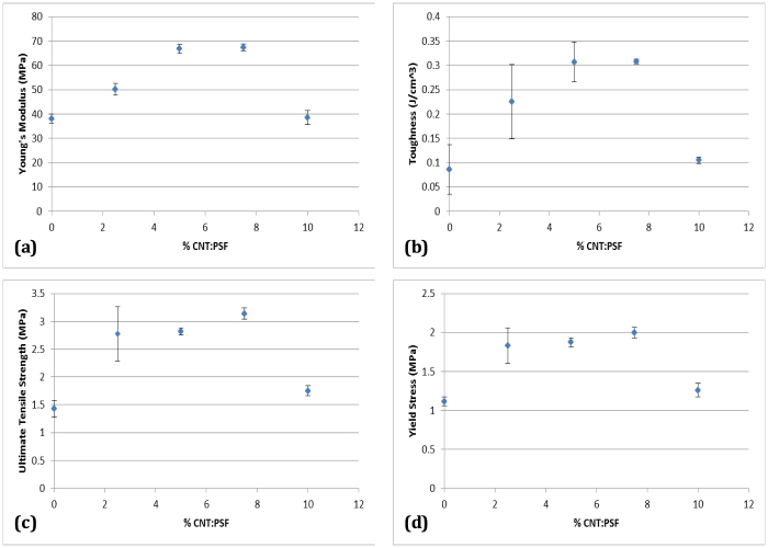
Figure 4 shows the results from the tensile tests conducted on the fabricated membranes. The Young's modulus and toughness increase with CNT concentration first and then decrease after a threshold concentration (7.5% CNT:PSF) is reached. This drop in mechanical properties is due to the ready re-agglomeration of CNTs creating bundles at higher concentrations. Studies have shown that CNT bundles display diminished mechanical properties compared to a single CNT26. As such, it is important to obtain even distribution of unclustered CNTs across the matrix. The mechanical properties obtained in this study and displayed in Figure 4 and the corresponding error bars are comparable to results obtained from diverse processing techniques27,28,29,30,31,32,33,34 with variables such as degree of dispersion of CNTs, CNT concentrations in the polymer, various polymer matrices etc. as all these parameters affect the mechanical properties. At 7.5% CNT concentration, there is a 119% increase in the ultimate tensile strength, 77% increase in the Young's modulus and 258% increase in the membrane toughness, all relative to 0% CNT concentration in the membrane. These values are quite favourable as there was no modification or purification of the CNTs used in the polymer solution. As-grown CNTs contain amorphous carbon and graphitic particles24 and it is possible to further improve the mechanical properties by using purified CNTs and other surface modification techniques.
Figure 4. Plots of (a) Young's modulus (MPa), (b) Toughness (J/cm3), (c) Ultimate tensile strength (MPa) and (d) Yield Stress (MPa) as a function of CNT loading in PSF.
At a concentration of 7.5% CNTs in the polymer composite, there is a 119% increase in the ultimate tensile strength, 77% increase in the Young's modulus, 258% increase in the toughness and a 79% increase in the yield strength. These increases are relative to 0% CNT loading.
Discussion
The rejection of oil by the membrane can be calculated using Equation 1:
where R is the rejection, and Cf and Cp are the feed and permeate concentrations, respectively. The flux through the membrane is determined using Equation 2,
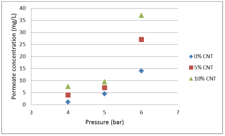
where F is the flux, A is the effective membrane area and V is the volume of permeate through the membrane during time t. The rejection values of the membrane calculated using Equation 1 are given in Table 1 and Figure 5 shows the permeate concentration values. There is an increase of the oil concentration in the permeate and a decrease in the membrane rejection with an increase in pressure. As the trans-membrane pressure increases, it rises above the capillary pressure of the membrane, which prevents the oil from entering the pores2, leading to the oil being forced through the pores. There is also a decrease in the membrane rejection with an increase in the CNT concentration in the membrane. This is expected as the structure of the PSF layer is altered by the membrane pores growing larger, with the addition of CNTs. The structure of the bottom layer in a thin film composite membrane has been shown to have an effect on the flux and the separation efficiency of the membrane17. Permeate concentrations below 10 mg/L are achieved at 4 and 5 bar pressures by all the membranes as seen in Figure 5.
Table 1. Rejection of oil by the CNT-polymer thin film membrane. Feed oil concentration is 287 mg/L.
| Pressure (bar) | CNT loading (%) | Rejection (%) |
|---|---|---|
| 4 | 0 | 99.65 |
| 4 | 5 | 98.61 |
| 4 | 10 | 97.39 |
| 5 | 0 | 98.43 |
| 5 | 5 | 97.56 |
| 5 | 10 | 96.69 |
| 6 | 0 | 95.12 |
| 6 | 5 | 90.59 |
| 6 | 10 | 87.11 |
Figure 5. The permeate concentration for different % CNT loading.
There is an increase in permeate concentration with an increase in pressure and % CNT loading. After 5 bar, the permeate concentration exceeds the lower limit of the allowable discharge concentration which is 10 mg/L.
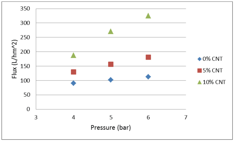
Figure 6 shows the flux calculated using Equation 2 for different % CNT loadings and pressures. The flux through the membrane increases with an increase in pressure and CNT concentration. The flux achieved in this study is comparable35 to or higher6,36 than previously reported values. Similar to the impact on membrane separation efficiency, the CNTs alter the pore structure of the PSF layer allowing for greater flux across the membrane. The SEM images (Figures 1 and 2) indicate an increase in pore diameter with an increase in the CNT concentration. The permeate flux can also be attributed to the PVA layer which is hydrophilic. It has been found that hydrophilic membranes are more resistant to fouling and generally have a higher permeate flux37,38. Cross-linking the PVA layer with dicarboxylic acid (maleic acid) has been shown to improve stability of the membrane17,39. The intramolecular crosslinked molecules are smaller in size than the initial polymer molecules with their size being dependent on the degree of crosslinking40. The results from Chunjin et al.37 show that a PVA membrane has high values of oil retention and permeation flux, and the flux recovery ratio is more than 95%, which demonstrates that the PVA membrane has excellent anti-fouling characteristics to oil. The incorporation of CNTs into the membrane used in this study show that it is still feasible to have such high flux recovery ratio whilst also increasing membrane mechanical strength. Finally, though the oil/water mixtures tested here are artificial and oil-containing waste water is known to have trace amount of surfactants, the results of this study are still meaningful and practical. Chakraborty et al.5 suggest that additives in oily waste water from plant operations will have an effect on the membrane performance. However, the oil particle size has a larger effect on the membrane performance relative to that by the additives in the oily waste water.
Figure 6. The flux through the membrane at different pressures and % CNT loading.
The increase in flux is due to the increase in % CNT loading which alters the membrane structure as can be seen in Figures 1 and 2.
In summary, a CNT-polymer composite membrane with a polyvinyl alcohol barrier layer has been fabricated and tested for the separation of oil from water. At a concentration of 7.5% CNTs in the polymer composite, a 119% increase in the ultimate tensile strength, 77% increase in the Young's modulus and 258% increase in the toughness were seen indicating the suitability of the membrane in practical applications. Increasing the trans-membrane pressure decreases the membrane separation but increases the flux. In the same way, increasing the CNT concentration in the membrane decreases rejection but increases membrane flux. Depending on the application of the membrane, a balance between the metrics such as rejection and flux can be obtained by varying CNT concentration in the membrane and pressure.
Methods
A vertically orientated continuous chemical vapour deposition (CVD) reactor was used to produce CNTs at 850°C as outlined in our previous studies24,25 using ferrocene which acts as both the catalyst and carbon source. 4 g of ferrocene was placed inside the vapouriser and the vapour was carried to the reactor by argon carrier gas. The solid carbon product of CNTs was collected from the cyclone and characterised using a transmission electron microscope (TEM) (JOEL 100S).
A phase inversion method17 was used to prepare the membranes in this study. A 10% (w/v) polysulfone (PSF) solution was prepared in dimethylformamide (DMF) under constant stirring. The solution was cast on a glass plate with the aid of a casting blade. The cast solution was left in ambient conditions for 10 s and thereafter fully immersed in distilled water for a period of 24 hours. A 1% (w/v) aqueous polyvinyl alcohol (PVA) solution was poured over the PSF membrane (which acts as the support) and kept in contact for 3 minutes after which the excess solution was drained off. A 1% maleic acid (MA), which acts as the cross-linker solution, was poured on the PVA layer and kept in contact for 3 minutes (to allow enough time for cross-linking) after which it was drained off. The membrane was then heated in an oven at 125°C for 15 minutes. The structure of the membranes was characterised using a scanning electron microscope (SEM) (FEI FIB/SEM Nova 600 Nanolab). BET (Brunauer-Emmett-Teller) analysis was conducted using the Tristar 3000 V6.05 A to obtain pore size information.
The CNTs were blended with the polymer solution in varying concentrations (from 0–10% w/v) before the solution was cast and immersed in water. The CNTs were dispersed with the aid of ultrasonic agitation in the membrane solution before casting. The mechanical tests on the membranes were carried out on the Hysitron Nanotensile 5000 Tester using thin rectangular (5 mm × 30 mm × 0.05 mm) samples of the membrane. The Young's modulus, toughness, ultimate tensile strength and yield stress were obtained from the mechanical tests.
For demonstration of oil-water separation, a reservoir was filled with distilled water (18 L) and synthetic oil (50 ml). The reservoir was continuously stirred and heated to 35°C to facilitate mixing. The mixture was pumped through the membrane and flow readings were taken using a rotameter. The concentration of oil in water (after ultrasonication and continued stirring) was found to be ~287 mg/L.
Author Contributions
SM, KM and their PhD supervisor SEI performed the experiments and analyzed the data. Everyone contributed to the interpretation of the results and writing the manuscript.
Acknowledgments
The authors acknowledge the financial support from the National Research Foundation (NRF) under South Africa Focus Area, NRF Nanotechnology flagship programme, Department of Science and Technology (DST)/NRF Centre of Excellence. The student bursaries provided by the University of the Witwatersrand are acknowledged. The work in Korea was supported by the World Class University program through the National Research Foundation of Korea funded by the Ministry of Education, Science and Technology under Project R31-10100.
References
- Siriverdin T. & Dallbauman L. Organic matrix in produced water from the osage-skiatook petroleum environmental research site. Chemosphere 57, 463–469 (2004). [DOI] [PubMed] [Google Scholar]
- Chakrabarty B., Ghoshal A. K. & Purkait M. K. Ultrafiltration of stable oil-in-water emulsion by polysulfone membrane. J. Membrane Sci. 325, 427–437 (2008). [Google Scholar]
- Bevis A. The treatment of oily water by coalescing. Filt. Sep. 295–301 (1992). [Google Scholar]
- Abadi S. R., Sebzari M. R., Rekabdar M. H. & Mohammadi T. Ceramic membrane performance in microfiltration of oily wastewater. Desalination 265, 222–228 (2011). [Google Scholar]
- Chakrabarty B., Ghoshal A. K. & Purkait M. K. Cross-flow ultrafiltration of stable oil-in-water emulsion. Chem. Eng. J. 165, 447–456 (2010). [Google Scholar]
- Mondal S. & Wickramasinghe S. R. Produced water treatment by nanofiltration and reverse osmosis membranes. J. Membrane Sci. 322, 162–170 (2008). [Google Scholar]
- Konieczny K. Modelling of membrane filtration of natural water or potable purposes. Desalination 143, 123–139 (2002). [Google Scholar]
- Lee K. P., Arnot T. C. & Mattia D. A review of reverse osmosis membrane materials for desalination–development to date and future potential. J. Membrane Sci. 370, 1–22 (2011). [Google Scholar]
- Gekas V. & Hallstrom B. Microfiltration membranes, cross-flow transport mechanisms and fouling studies. Desalination 77, 195–218 (1990). [Google Scholar]
- Wakeman R. J. & Williams C. J. Additional techniques to improve microfiltration. Sep. Purif. Technol. 26, 3–18 (2002). [Google Scholar]
- Durancear S. J. Membrane Practices for Water Treatment. Denver: American Water Works Association (2001). [Google Scholar]
- Van der Bruggen B. & Vandecasteele C. Distillation vs. membrane filtration: overview of process evolutions in seawater desalination. Desalination 143, 207–218 (2002). [Google Scholar]
- Van der Bruggen B., Manttari M. & Nystromb M. Drawbacks of applying nanofiltration and how to avoid them: a review. Sep. Purif. Technol. 63, 251–263 (2008). [Google Scholar]
- Al-Amoudi A. & Lovitt R. W. Fouling strategies and the cleaning system of NF membranes and factors affecting cleaning efficiency. J. Membrane Sci. 303, 6–28 (2007). [Google Scholar]
- Hirai T., Asada Y., Suzuki T. & Hayashi S. Studies on elastic hydrogel membrane. I. effect of preparation conditions on the membrane performance. J. Appl. Polymer Sci. 38, 491–502 (1989). [Google Scholar]
- Ibrahim N. A. & Abo-Shosha M. H. Preparation and characterization of carboxylic cation exchange resins from the reaction of poly(vinyl alcohol) with melamine-formaldehyde and some hydroxy acids. Angewandte Makromolekulare Chemie 210, 7–20 (1993). [Google Scholar]
- Gohil J. M. & Ray P. Polyvinyl alcohol as the barrier layer in thin film composite nanofiltration membranes: Preparation, characterization, and performance evaluation. J. Colloid Interface Sci. 338, 121–127 (2009). [DOI] [PubMed] [Google Scholar]
- Huang R. Y. M. & Rhim J. W. Modification of poly (viny1 alcohol) using maleic acid and its application to the separation of acetic acid-water mixtures by the pervaporation technique. Polymer Inter. 30, 129–135 (1993). [Google Scholar]
- Gimenez V., Mantecon A. & Cadiz V. Crosslinking of poly (viny1 alcohol) using dianhydrides as hardeners. J. Appl. Polymer Sci. 59, 425–431 (1996). [Google Scholar]
- Meyyappan M. Carbon Nanotubes: Science and Applications. CRC Press, Boca Raton, FL. (2004).
- Bagchi A. & Nomura S. On the effective thermal conductivity of carbon nanotube reinforced polymer composites. Comp. Sci. Technol. 66, 1703–1712 (2006). [Google Scholar]
- Valentini L. et al. Electrical transport properties of conjugated polymer onto self-assembled aligned carbon nanotubes. Diamond Rel. Mater. 12, 1524–1531 (2003). [Google Scholar]
- Coleman J. N., Khan U. & Gunko Y. K. Mechanical reinforcement of polymers using carbon nanotubes. Adv. Mater. 18, 689–706 (2006). [Google Scholar]
- Yah C. S., Simate G. S., Moothi K., Maphutha K. S. & Iyuke S. E. Synthesis of large carbon nanotubes from ferrocene: the chemical vapour deposition technique. Trends Appl. Sci. 6, 1270–1279 (2011). [Google Scholar]
- Iyuke S. E. et al. Process synthesis and optimization for the production of carbon nanostructures. Nanotechnology 20, 375602 (2009). [DOI] [PubMed] [Google Scholar]
- Coleman J. N., Khan U., Blau W. J. & Gunko Y. K. Small but strong: A review of the mechanical properties of carbon nanotube-polymer composites. Carbon 44, 1624–1652 (2006). [Google Scholar]
- Qian D., Dickey E. C., Andrews R. & Rantell T. Load transfer and deformation mechanisms in carbon nanotube-polystyrene composites. Appl. Phys. Lett. 76, 2868–2870 (2000). [Google Scholar]
- Kearns J. C. & Shambaugh R. L. Polypropylene fibers reinforced with carbon nanotubes. J. Appl. Polymer Sci. 86, 2079–2084 (2002). [Google Scholar]
- Gorga R. E. & Cohen R. E. Toughness enhancements in PMMA by addition of oriented MWCNTs. J. Polymer Sci. 42, 2690–2702 (2004). [Google Scholar]
- Fornes T. D., Baur J. W., Sabba Y. & Thomas E. L. Morphology and properties of melt-spun polycarbonate fibers containing single- and multi-wall carbon nanotubes. Polymer 47, 1704–1714 (2006). [Google Scholar]
- Cadek M., Coleman J. N., Barron V., Hedicke K. & Blau W. J. Morphological and mechanical properties of CNT-reinforced semicrystalline and amorphous polymer composites. Appl. Phys. Lett. 81, 5123–5125 (2002). [Google Scholar]
- Chae H. G., Sreekumar T. V., Uchida T. & Kumar S. A comparison of reinforcement efficiency of various types of carbon nanotubes in polyacrylonitrile fiber. Polymer 46, 10925–10935 (2005). [Google Scholar]
- Ogasawara T., Ishida Y., Ishikawa T. & Yokota R. Characterization of MWNT/phentlethynyl terminated polyimide composites. Composites A 35, 67–74 (2004). [Google Scholar]
- Xiong J. et al. Thermal & mechanical properties of a polyutherane/MWCNT composite. Carbon 44, 2701–2707 (2006). [Google Scholar]
- Ebrahimi M. et al. Characterization and application of different ceramic membranes for the oil-field produced water treatment. Desalination 245, 533–540 (2009). [Google Scholar]
- Kong Y. et al. Separation performance of polyimide nanofiltration membranes for solvent recovery from dewaxed lube oil filtrates. Desalination 191, 254–261 (2006). [Google Scholar]
- Chunjin W. et al. Treatment of oily water by a poly(vinyl alcohol) ultrafiltration membrane. Desalination 225, 312–321 (2008). [Google Scholar]
- Srijaroonrat P., Julien E. & Aurelle Y. Unstable secondary oil/water emulsion treatment using ultrafiltration: fouling control by backflushing. J. Membrane Sci. 159, 11–20 (1999). [Google Scholar]
- Gohil J. M., Bhattacharya A. & Ray J. Studies on the cross-linking of poly (vinyl alcohol). J. Polymer Res. 13, 161–169 (2006). [Google Scholar]
- Gebben B., Van den-Berg H. W. A., Bargeman D. & Smolders C. A. Intramolecular crosslinking of poly (vinyl alcohol). Polymer 26, 1737–1740 (1985). [Google Scholar]


