Abstract
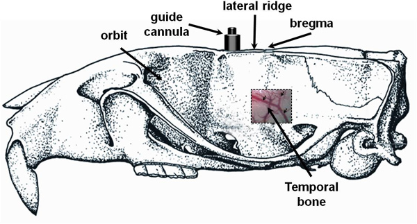
Creation of a cranial window is a method that allows direct visualization of structures on the cortical surface of the brain1-3. This technique can be performed in many locations overlying the rat cerebrum, but is most easily carried out by creating a craniectomy over the readily accessible frontal or parietal bones. Most frequently, we have used this technique in combination with the endothelin-1 middle cerebral artery occlusion model of ischemic stroke to quantify the changes in middle cerebral artery vessel diameter that occur with injection of endothelin-1 into the brain parenchyma adjacent to the proximal MCA4, 5. In order to visualize the proximal portion of the MCA during endothelin -1 induced MCAO, we use a technique to create a cranial window through the temporal bone on the lateral aspect of the rat skull (Figure 1). Cerebral arteries can be visualized either with the dura intact or with the dura incised and retracted. Most commonly, we leave the dura intact during visualization since endothelin-1 induced MCAO involves delivery of the vasoconstricting peptide into the brain parenchyma. This bypasses the need to incise the dura directly over the visualized vessels for drug delivery. This protocol will describe how to create a cranial window to visualize cerebral arteries in a step-wise fashion, as well as how to avoid many of the potential pitfalls pertaining to this method.
Keywords: Medicine, Issue 72, Neurobiology, Neuroscience, Biomedical Engineering, Anatomy, Physiology, Genetics, Genomics, Surgery, Ischemic stroke, Cerebrovascular, Brain, Cranial window, Rat, Endothelin-1, temporal craniectomy, animal model
Protocol
This protocol was approved by the Institutional Animal Care and Use Committee (IACUC) at the University of Florida and is in compliance with the "Guide for the Care and Use of Laboratory Animals" (eighth edition, National Academy of Sciences, 2011).
Materials
Animals: Eight-week-old, male, Sprague Dawley rats (Charles River Farms, Wilmington, MA, USA) weighing 250-300 g at the time of surgery.
- Anesthesia
- Inhalation anesthesia system (VetEquip Inc., Pleasanton, CA, USA)
- Isoflurane anesthetic (Baxter Pharmaceutics, Deerfield, IL, USA)
- Stereotaxic system (David Kopf Instruments, Tujunga, CA, USA)
- Small animal stereotaxic system
- Non-rupture ear bars for rats
- Gas anesthesia head holder for rats
- Temperature regulation
- BAT-12 microprobe thermometer (World Precision Instruments, Inc., Sarasota, FL, USA)
- T/PUMP, TP600 Thermal blanket (Gaymar Industries, Inc., Orchard Park, NY, USA)
- Surgical instruments
- Metzenbaum scissors, iris forceps, bulldog clamp retractors, 10 μl syringe with 26 gauge beveled needle, Bovie cautery kit (World Precision Instruments, Inc., Sarasota, FL, USA)
- Micromotor drill (Stoelting, Wood Dale, IL, USA)
- 0.8 mm round drill bur (Roboz Surgical Instrument Co., Inc., Gaithersburg, MD, USA)
- STORZ Bonn Suturing Forceps (Bausch and Lomb, Inc., Rochester, NY, USA)
- Surgical Supplies
- 3.0 nylon suture (Oasis, Mettawa, IL, USA)
- Cotton swabs, Puralube eye ointment (Fisher Scientific, Pittsburg, PA, USA)
- Surgical points and strips (Medtronic Xomed, Inc., Jacksonville, FL, USA)
- Electric hair clippers (Oster, Providence, RI, USA)
- Chemicals
- Endothelin-1 (American Peptide, Sunnyvale, CA, USA)
- Chlorhexidine 2% (Agrilabs, St. Joseph, MO, USA)
- Visualization Equipment
- Surgical microscope (Seiler Instrument and Manufacturing; St. Louis, MO, USA)
- Sony Handycam HDR-SR12 (Sony, Minato, Tokyo, Japan)
- Fiber Optic illuminator (TechniQuip Corp., Livermore, CA, USA)
- Measurement of vessel diameter
- VLC media player (Paris, France)
- Image J software (ImageJ 1.42q software, U.S. National Institutes of Health, Bethesda, MA, USA)
1. Pre-surgical Steps
Prior to surgery, the rats are housed under a 12:12 light/dark cycle with free access to water and rodent chow.
Anesthesia is induced with 4% isoflurane in 100% O2 gas mixture in an induction chamber.
The crown of the head is shaved with electric hair clippers.
The rat is placed in a prone position on an absorbent pad lying on a temperature-controlled operating surface (thermal blanket) and the head is placed in the stereotactic apparatus starting with placement of the gas anesthetic face mask.
Next, the ear bars are inserted and tightened.
During the procedure anesthesia is maintained with 2% isoflurane in 100% O2 gas mixture.
Opthalmic lubricant ointment is applied to both eyes, and the eyelids are closed to prevent eye desiccation during the surgical procedure.
A rectal temperature probe is inserted to maintain a constant animal core temperature of 37±0.5 °C.
With the head of the anesthetized rat held firmly in the stereotaxic device the surgical area is cleansed with alternating chlorhexidine and saline three times.
2. Pre-cranial Window Preparation
Prior to creating a cranial window, the rat should be prepared for any experiments by implantation of other required hardware and should receive any required surgical procedures. For this protocol, we have previously implanted a guide cannula for endothelin-1 (ET-1) induced MCAO as shown in a companion publication titled "Endothelin-1 Induced Middle Cerebral Artery Occlusion Model for Ischemic Stroke with Laser Doppler Flowmetry Guidance in Rat."
3. Creation of the Cranial Window
After placement of a guide cannula or equipment required for experimentation, a cranial window is created to directly visualize proximal portions of the middle cerebral artery during a stroke procedure.
First, scissors are used to incise the skin overlying the temporalis muscle starting medially and working laterally.
The temporalis muscle is bisected using electrocautery and then retracted using 3.0 nylon suture to visualize the squamous portion of the temporal bone.
An approximately 3-4 mm square is drawn on the squamous portion of the temporal bone caudal to the orbit and superior to the base of the zygomatic process as it reflects off of the temporal bone.
A drill is used to gradually cut the outlined piece of bone free from the temporal bone. Care should be taken to avoid applying too much pressure to the drill since it is possible to damage the dura or cerebral cortex.
Frequent rinses with sterile saline are performed to improve visualization of the surgical field and prevent overheating of the skull.
Starting at a loose corner, the piece of temoporal bone is carefully removed using fine rat-toothed forceps while making sure not to tear any vessels associated with the dura.
The dura is left intact and debris is rinsed away using sterile saline.
4. Recording of Cerebral Artery Constriction
To demonstrate how to capture images in real time, a rat that is undergoing ET-1 induced MCAO is used for this protocol.
Prior to application of vasoactive compounds, a baseline video should be recorded for at least 1 min. For ET-1 induced MCAO, the baseline recording is made once the needle has been lowered into the brain parenchyma but prior to the ET-1 injection.
The syringe pump is started for injection and recorded for 1 hr or until the desired endpoint. The needle is left in place during video recording in order to prevent disturbances of the focal plane.
The rat should be deeply anesthetized and euthanized according to an approved protocol following this procedure.
5. Image Analysis
Vessel diameter can be determined for any part of the visualized MCA. As an example, we will use one branch of the MCA to measure vessel diameter at time-points before and after ET-1 injection. Still frames from the video are captured at 1 min intervals using VLC media player (VideoLAN).
VLC player is installed and opened.
By selecting tools and then preferences, the setting is changed to "All" under "Show settings."
The "video menu" is expanded in the left side bar and "output modules" is then expanded. "Scene filters" is selected to bring up the scene video filter menu.
"Scene" is typed into the box for filename prefix.
A directory path prefix is defined. This is where still frames are saved.
A recording ratio is selected based on the desired rate of still frame capture. If a video was captured at 29 frames per sec, then "1749" (29 frames/sec x 60 sec/min) should be entered in the box to save one still frame every 1 min. All changes are then saved.
The desired video is then opened in VLC player to automatically save still frames once every 1 min.
Vessel diameter is then measured using these images. First, ImageJ software (NIH) is opened.
Then the still frames that you will measure are opened in ImageJ.
By selecting the "analyze" menu, "set measurements" is then opened and all boxes are unchecked.
Next, the straight line tool is selected.
The keyboard shortcut "Ctrl +" is used to zoom in as needed and a line is placed perpendicular to the vessel path to measure vessel diameter.
Finally, vessel length is obtained by selecting the "analyze" menu and then "measure" (ctrl+M) to obtain vessel length.
This process is repeated at least three times and averaged for each measured vessel measured in each still frame.
Vessel diameter at each time point is normalized to the baseline vessel diameter so that comparisons can be made using multiple rats. To do this, use the formula current diameter/baseline diameter x 100% to calculate the % baseline diameter of each vessel.
Representative Results
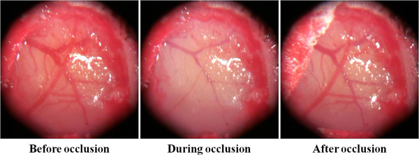
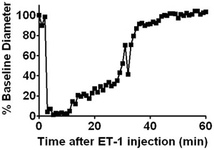
Still images taken from the captured video show that the change in cerebral artery diameter after ET-1 injection can be readily appreciated using this cranial window technique (Figure 2). Within minutes of ET-1 injection, the vessel will begin to constrict. Eventually the vessels will be difficult to visualize and the brain tissue will become pale. After about 20 min the effects of ET-1 will diminish and the vessels will begin to dilate, gradually returning to baseline diameter after about 45 min. In addition to the more obvious vasoconstriction that occurs, the cortical surface becomes paler after ET-1 administration. It is possible to calculate the absolute change in vessel diameter with a calibrated microscope reticle if desired. For comparison between multiple rats we calculate the relative change in vessel diameter that occurs during a procedure. These measurements are performed using ImageJ software (NIH). Then a graph representing the relative changes in vessel diameter over time can then be constructed (Figure 3).
 Figure 1. Diagram of the location of temporal craniectomy. This diagram depicts the skeletal anatomy of the rat skull with anterior oriented to the left. The temporalis muscle has its origin along the lateral skull ridge. This muscle must be detached from this ridge and bisected in order to visualize the squamous portion of the temporal bone. An approximately 3-4 mm craniectomy can be performed at this location just posterior to the orbit and superior to the base of the zygomatic process as it reflects off of the temporal bone. The large arrow indicated the location to perform the craniectomy. The 3 small arrows indicate the MCA and its branches. All arteries in this location will be branches of the MCA and arteries can be distinguished from veins by both their non-tortuous appearance and sensitivity to vasoactive compounds.
 Figure 2. Cranial window before ET-1 injection, after ET-1 injection, and after reperfusion. Starting at the left, a representative image of MCA branches as viewed through a cranial window is shown. Arteries can be identified by their morphology. The relatively straight MCA enters the field at the lower left and has one major branch point in this image. Other vessels in these pictures are cerebral veins which can be identified by their deeper tone and tortuous appearance. During occlusion arteries will rapidly constrict and the tissue will become pale. Slowly, the artery will dilate and return to baseline diameter.
 Figure 3. Representative vessel diameter over time for a single rat. Percent baseline diameter can be calculated over time using the simple formula, current diameter/baseline diameter x 100%. This can be done with any vasoactive compound.
Discussion
In summary, this cranial window preparation technique is very versatile as it can be altered to meet the needs of many experiments with minor modifications4, 5. For example, we have successfully monitored cerebral blood flow in specific MCA branches using laser doppler flowmetry to focus directly on a cerebral artery visualized through a cranial window (Mecca AP 2009 and 2011). In addition, a similar preparation with the dura incised can be used with topical administration of vasoactive compounds to create an in vivo vascular reactivity bath3. Several factors should be taken into consideration when preparing a cranial window in order to decrease the failure rate for this technique. Many of these factors are related to obtaining good visualization of cerebral arteries. First, care must be taken when creating the craniectomy so that the dura or blood vessels overlying it are not disrupted with the drill bit. This is best accomplished by frequent washes with sterile saline to clear debris and cool the skull. Second, the bone fragment should be lifted gently when it is removed. If the fragment does not pull away easily, then the drill bit should be used to cut away more bone. Lastly, small amounts of blood or CSF can easily alter the appearance of the cranial window during this procedure. The craniectomy performed provides an opening in the skull that is larger than required for visualization. Therefore, it is easy to place several absorbent sponges in the dependent portion of the surgical site to prevent fluid from accumulating. These sponges can be changed as needed if care is used not to obstruct the window with surgical tools.
Disclosures
No conflicts of interest declared.
Acknowledgments
This work was supported by grants from the American Heart Association Greater Southeast Affiliate (09GRNT2060421), the American Medical Association, and from the University of Florida Clinical and Translational Science Institute. Adam Mecca is a NIH/NINDS, NRSA predoctoral fellow (F30 NS-060335). Robert Regenhardt received predoctoral fellowship support from the University of Florida Multidisciplinary Training Program in Hypertension (T32 HL-083810).
References
- Levasseur JE, Wei EP, Raper AJ, Kontos AA, Patterson JL. Detailed description of a cranial window technique for acute and chronic experiments. Stroke. 1975;6:308–317. doi: 10.1161/01.str.6.3.308. [DOI] [PubMed] [Google Scholar]
- Baumbach GL, Dobrin PB, Hart MN, Heistad DD. Mechanics of cerebral arterioles in hypertensive rats. Circ. Res. 1988;62:56–64. doi: 10.1161/01.res.62.1.56. [DOI] [PubMed] [Google Scholar]
- Regrigny O, et al. Effects of melatonin on rat pial arteriolar diameter in vivo. Br. J. Pharmacol. 1999;127:1666–1670. doi: 10.1038/sj.bjp.0702714. [DOI] [PMC free article] [PubMed] [Google Scholar]
- Mecca AP, O'Connor TE, Katovich MJ, Sumners C. Candesartan pretreatment is cerebroprotective in a rat model of endothelin-1-induced middle cerebral artery occlusion. Exp. Physiol. 2009;94:937–946. doi: 10.1113/expphysiol.2009.047936. [DOI] [PMC free article] [PubMed] [Google Scholar]
- Mecca AP, et al. Cerebroprotection by angiotensin-(1-7) in endothelin-1-induced ischaemic stroke. Exp. Physiol. 2011;96:1084–1096. doi: 10.1113/expphysiol.2011.058578. [DOI] [PMC free article] [PubMed] [Google Scholar]


