Abstract
We describe a GPU-accelerated framework that efficiently models spatially (shift) variant system response kernels and performs forward- and back-projection operations with these kernels for the DIRECT (Direct Image Reconstruction for TOF) iterative reconstruction approach. Inherent challenges arise from the poor memory cache performance at non-axis aligned TOF directions. Focusing on the GPU memory access patterns, we utilize different kinds of GPU memory according to these patterns in order to maximize the memory cache performance. We also exploit the GPU instruction-level parallelism to efficiently hide long latencies from the memory operations. Our experiments indicate that our GPU implementation of the projection operators has slightly faster or approximately comparable time performance than FFT-based approaches using state-of-the-art FFTW routines. However, most importantly, our GPU framework can also efficiently handle any generic system response kernels, such as spatially symmetric and shift-variant as well as spatially asymmetric and shift-variant, both of which an FFT-based approach cannot cope with.
Index Terms: CUDA, DIRECT TOF PET Reconstruction, Forward and back-projection, GPU, Spatially varying kernels
I. Introduction
The introduction of Time-Of-Flight (TOF) information to positron emission tomography (PET) image reconstruction has been a decisive advancement. Having TOF information available makes it possible for a point of annihilation (or an event) to be much more accurately predicted than with conventional PET imaging. This improved localization reduces noise in the imaging data, resulting in higher image quality, shorter imaging times, and/or lower dose to the patient [1–4].
A full realization of the TOF information requires proper reconstruction tools. The DIRECT (Direct Image Reconstruction for TOF) [5] is a novel approach for TOF reconstruction and is more efficient than traditional list-mode and binned TOF-PET reconstruction approaches [6][7]. In the binned aproaches, the events are binned by their Line-Of-Response (LOR) and arrival time to form a set of histo-projections, one for each angular view. On the other hand, in the DIRECT approach the events are first sorted into a (sub)set of angular views and then deposited for each view into a dedicated histo-image, each having the same lattice configuration and the same voxel resolution as the reconstructed image.
As in any TOF iterative reconstruction, DIRECT requires convolution-like operations (forward- and back-projections) in each corrective update using the system response (SR) kernels to model the scanner’s timing (TOF) and detector (LOR) resolution functions. These operations can be performed efficiently in Fourier space when the SR kernels are spatially (shift) invariant. However, in practical applications the SR kernels are not shift-invariant. Rather, their width considerably increases towards the edge of the FOV and becomes asymmetric towards the edge of the scanner. Also, a kernel’s size is typically quite large – in our specific application it is 300–600 ps (45–90 mm FWHM) of TOF resolution and 5–10 mm FWHM of LOR resolution in the axial and radial directions [8][9]. Handling these types of SR kernels in the Fourier domain is difficult, while operating in the spatial domain is computationally very expensive. We have sought to overcome this challenge by GPU-acceleration [10][11], exploiting the massively parallel computations they allow.
Mapping a CPU-based algorithm to the GPU and achieving 1–2 orders of speed-up is typically not straightforward. The CPU-based algorithm often needs to be reordered or decomposed to fit optimally to the GPU architecture and programming model. A critical component in GPU architectures is the memory. It is organized into a hierarchy, with some of it on-chip but the majority off-chip (but on-board). The former is orders of magnitudes faster. As it takes 100s of clock cycles to bring off-chip data into on-chip memory, it is of utmost importance to re-use the local data among the parallel threads as much as possible. Also, since on-chip memory is quite small (in the order of kilobytes), careful occupancy planning of this limited resource is equally important.
The SR kernel has a much wider width in the TOF direction than in the other directions. Since it can traverse the histo-image space at arbitrary angles, the data access at these off-axis orientations is non-sequential. To achieve a maximum utilization of on-chip GPU memory for these off-axis directions, we recently proposed a two-stage scheme [12]. It first resampled (rotated) the data into a storage pattern aligned with the TOF direction of the SR kernels, allowing for fast linear access in on-chip memory. By subtracting the smoothing effects of the resampling interpolation kernel from the SR kernel, we were able to compensate for the interpolation kernel’s blurring effects. However, despite the system’s good time performance, it has two major limitations: (1) practical interpolation kernels are often wider than the actual detector resolution and thus the subtraction of the interpolator effects from the SR kernel is not fully possible, and (2) the method is only applicable for symmetric SR kernels, ignoring that accurate SR kernels have some degree of asymmetry at large radii.
We chose to go a different route by using a one-stage method which does not require prior interpolation. Here we aimed for a method that (1) maximizes memory cache performance by carefully selecting GPU memory based on the access patterns to the memory and (2) minimizes latency stemming from memory operations on both thread and instruction levels.
Our paper is organized as follows. Section II provides more detail on the forward- and backward-operations of DIRECT. Section III covers relevant background of both GPU architecture and programming model. Section IV describes the methodology and technical detail of our approach, while experimental results are presented in sections V and VI.
II. Projection In DIRECT
The characteristics of the SR kernels are determined by the TOF-PET detector. In this work, we considered an experimental full-ring TOF-PET detector based on the LaBr3 crystals developed at the University of Pennsylvania [8][9]. It has about 300–400 ps TOF resolution (45–60 mm). The TOF information gives the probability of where a detected event was generated along its LOR. Furthermore, an event can be observed at multiple detector crystals due to detector resolution effects, called LOR resolution. Practical LOR blurring in a whole body scanner can vary within a range of 5–10 mm FWHM in the LOR radial direction. The variation in the LOR axial direction is relatively small and consequently it is kept constant in this study. The SR kernels we considered have ellipsoidal-like shapes with wider width in the TOF direction and a varying FWHM in the LOR radial direction.
Iterative reconstruction typically alternates projection and back projection. In DIRECT, the forward-projection operator projects an image into histo-image space. The discrepancy (ratio) between these simulated projection data and the measured (histo-image) data obtained from the scanner is then back-projected into image space to reconstruct a corrected image. As mentioned, it is the distinguishing feature of the DIERCT approach that both of these operations occur in the same lattice configuration and at the same voxel resolution.
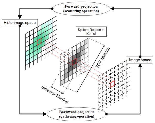
In DIRECT both forward and backward projection operations become convolution-like operations using the SR kernels [5]. The forward-projection can be interpreted as a scattering operation, where each image voxel spreads its value to its neighbors, weighted by that voxel’s SR kernel. In contrast, the back-projection (transpose of the forward-projection) can be described as a gathering operation, where each voxel collects values from its neighbors, weighted by that voxel’s SR kernel. Fig. 1 gives an illustration. For the symmetric shift-invariant SR kernels, both projection and back-projection operations are equivalent 3D convolution operations, which can be handled efficiently by means of FFT [5]. However, in the case of shift-variant and/or asymmetric SR kernels, projection and back-projection operations must be strictly distinguished and handled in the spatial domain because the FFT cannot handle such generic system resolution models. Detailed comparisons and explanations will be discussed in section V.B.
Fig. 1.
Forward- and backward-projection in DIRECT.
III. NVIDIA GPU Architecture And Its Programming Model, CUDA
We have accelerated both forward- and back projections on a NVIDIA GTX 285 GPU with 1GB DDR3 off-chip memory. This GPU has 240 CUDA cores organized into 30 streaming multiprocessors (SM) of 8 scalar processors (SP) each. Groups of SMs belong to Thread Processing Clusters (TPC). This GPU, like all modern GPUs, has off-chip memory including global, texture and constant memory which all incur hundreds of cycles of memory latency. Access to off-chip memory is often the bottleneck of a GPU application. Fortunately, texture and constant memory are cached, replacing the hundreds of cycles of latency with only a few cycles for on-chip cache access. The CUDA (Computer Unified Device Architecture) is a C-like API used to program NVIDIA GPUs. Execution of a CUDA kernel (or function) invokes multiple threads which are organized into thread blocks on a grid. The GTX 285 can have a maximum of 512 threads per block. Some important parameters for the GTX 285 architecture and its CUDA programming model are listed in Table I [13][14].
TABLE I.
NVIDIA GTX 285 GPU Parameters
| GPU Organization | |
|---|---|
| TPCs (Thread Processing Cluster) | 10 total |
| SMs (Streaming Multiprocessor) | 3 per TPC |
| Shader Clock | 1.48 GHz |
| Memory (DRAM) Clock | 1.24 GHz |
| Memory (DRAM) Bus Width | 512-bit |
| Memory (DRAM) Latency | 400 – 600 cycles |
|
| |
| SM Resources (30 SMs total)
| |
| SPs (Scalar Processor) | 8 per SM |
| SFUs (Special Function Unit) | 2 per SM |
| DPUs (Double Precision Unit) | 1 per SM |
| Registers | 16,384 per SM |
| Shared Memory | 16 KB per SM |
| Constant Cache | 8 KB per SM |
| Texture Cache | 6–8 KB per SM |
|
| |
| Programming Model
| |
| Warps | 32 threads |
| Max number of threads per block | 512 threads |
| Max sizes of each dimension of a block | 512 x 512 x 64 |
| Max sizes of each dimension of a grid | 65,535 x 65,535 x 1 |
| Global Memory | 1 GB total |
| Constant Memory | 64 KB total |
Each SM uses a 24-stage and in-order SIMD pipeline without forwarding [13]. Since there are 8 SPs in one SM this implies that at least 192 active threads are needed to avoid stalling for true data dependencies between consecutive instructions from a single thread. All threads in a SM are scheduled in the SIMD pipeline in a unit called warp. A warp is a collection of 32 threads, executing the same instruction with different data values over four consecutive clock cycles in all pipelines. A warp has zero scheduling overhead on a fine-grained basis [15] and so can be easily replaced by another, ready warp when one of its threads is stalled due to a memory request. In the following subsections, we will discuss thread occupancy and thread efficiency, as well as thread-level parallelism and instruction-level parallelism. Since these are strongly related to the usage of GPU resources and so have a large impact on the performance of a GPU application, it is important to have a good understanding of them.
A. Thread occupancy and efficiency
The thread occupancy is defined as the number of active threads per thread block (in percent of the device’s full capacity); while the thread efficiency is defined as the overall computational efficiency of the individual threads [16]. Running more threads in a thread block results in higher thread occupancy, and this can hide long memory latencies thanks to the fast context switching among warps. However, higher thread occupancy also requires more memory to store state and data for all of these threads. Since there is only a very limited amount of on-chip resources, this can then lead to an increased use of high-latency off-chip memory, lowering thread efficiency. On the other hand, if a thread block fully utilizes the on-chip resources to obtain higher thread efficiency the total number of threads in the thread block will be restricted, lowering thread occupancy. Faced with this conflict, it is important to finely tune the amount of on-chip resources allocated to each thread by optimizing this trade-off.
B. Two forms of parallelism in CUDA: TLP and ILP
There are two forms of parallelism in CUDA: thread-level (TLP) and instruction-level (ILP) parallelism. Both forms identically identify independent instructions but in different granularities of parallelism [17]. As CUDA models the GPU architecture as a multi-core system, it abstracts the TLP of the GPU into a hierarchy of threads [13]. The more threads a thread block has the higher the TLP and therefore the higher the thread occupancy. TLP is achieved by invoking the CUDA functions with a sufficiently large number of threads.
On the other hand, ILP can be achieved by executing multiple independent instructions in each thread. Then, while a thread is waiting for long-latency memory, it executes another independent instruction instead of switching its context. For example, unrolling a loop in a kernel function can increase the ILP. It is obvious that increasing ILP will generate higher usage of on-chip memory and thus will yield higher thread efficiency (but lower thread occupancy). In our work, we explore both forms of parallelism for both projection operators and the results are evaluated with time performance as well as thread occupancy measures (see section V.A).
IV. Methods
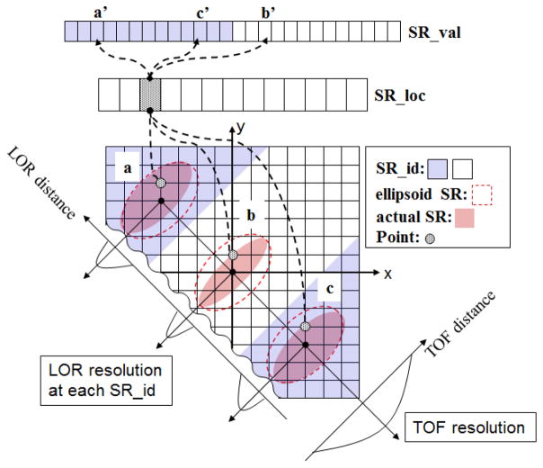
We pre-compute a set of shift-variant SR kernels and store them in different types of GPU memory to maximize memory cache performance. For this, we first create a shift-invariant elliptical SR kernel that has maximum TOF and LOR resolution. The information of the elliptical SR kernel is divided into location and value information (SR_loc and SR_val in Fig. 2). Here, the location information refers to the Cartesian coordinate of the SR kernel’s origin and the value information refers to the actual kernel values at a voxel in histo-image space. To handle shift-variant SR kernels, the histo-image is segmented according to the LOR distance, which is defined as the distance from the center of the image data to a voxel in the LOR radial direction (SR_id in Fig. 2). The SR_id is a 2-D look-up table of the same size (width and height) as the image transverse slice. It only needs to be computed once, in both non-tilt and tilt cases. As discussed in section II, the LOR resolution only varies in the radial direction. Both SR_loc and SR_val arrays are stored in (linear) global memory such that each thread can access them in a coalesced manner. Finally, while the accesses to the SR_id for each thread are spread out, they are well localized within the shape of the elliptical SR kernel. This kind of memory access pattern (called 2-D cloud) is very efficient with texture memory and its cache [18]. The image data are also mapped to texture memory for similar reasons.
Fig. 2.
Modeling spatially variant SR kernels. In this illustration, there are two regions (blue and white) having different LOR resolution in the radial direction. In each region, the ellipsoid SR kernel (red-dot boundary) shares the same location information (SR_loc) for the grid points within the kernel. For example, SR_loc will return (0, 1) for all points in the kernels (a, b, and c). This information can be used to fetch image data at those points by adding the origin of each kernel. However, each kernel can have a different SR_val according to its region. Assuming SR_loc is a following row-major order, for example, SR_val will return a′ and b′ for the points in a and b, respectively; but, for the point in c, SR_val will return c′ by fetching it in reverse order.
This method has the following two advantages: (1) unlike our previous work [12], it does no longer require an interpolation kernel, and (2) projection operations are much easier to implement since the (enclosing maximum) outline of the elliptical SR kernels is always symmetric and shift-invariant. Fig. 2 illustrates via a 2-D space example how the elliptical SR kernel is modeled and utilized.
A. GPU implementation of the projection operations
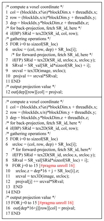
In back-projection, each thread performs the gather operation for its target voxel as follows: (1) compute the coordinate of the voxel and select SR_val by fetching SR_id, and (2) collect the values of the voxel neighbors and multiply them by the values of the selected SR kernel mapped to these voxels locations. In contrast, the forward projection is a scattering operation. It is different from back-projection in that each voxel writes and updates its neighbors weighted by the corresponding kernel value (see section II).
The GPU gather operations are more efficient than scatter operations because memory reads can be cached and are therefore faster than memory writes. Moreover, gather operations can avoid write hazards (or race conditions) by writing data in an orderly fashion, while scatter operations require slower atomic operations to avoid such hazards [18]. For these reasons, we converted the scatter operation of the forward-projection into a gather operation. Note that this (forward-projection) gather operation is different from the back-projection gather operation for the variant and/or asymmetric kernels in that the kernel itself is dependent on the neighbor’s location and not just its looked-up value. Also, the SR kernels used here are radially flipped versions of the SR kernels used for the backprojection operation.
We combine TLP with ILP to minimize the long memory latency associated with fetching the SR_val, SR_loc, SR_id and image data within the gather operations. We add ILP to TLP by assigning multiple voxels to each thread. The voxels are chosen along the axial direction (z-axis) so that we can keep the same voxel access pattern for the SR_id and image data. Also, the instructions for these voxels are unrolled to hide latencies among them. Fig. 3 gives the pseudo code for [TLP only] and for [TLP+ILP].
Fig. 3.
Pseudo CUDA code for projection operations. [top] TLP only. [bottom] TLP+ILP. In the top, each thread does gathering operations for one output, while, in the bottom, the gathering operations are performed for 16 outputs (experimentally chosen) per thread.
V. Analysis Of Projection Operations
A. Time performance analysis
Table II gives relevant CUDA statistics for the projection code and the average time performance for a one of the views. As described in section IV, the projection code with ILP consumes more registers per thread and it causes lower thread occupancy. However, the ILP more efficiently handles the long latency associated with fetching the SR information and the image data. This efficiency results in better time performance in ILP (about 2 times faster than TLP only). There is also almost no difference between the times required for forward projection and back projection. These findings impressively demonstrate that in order to optimize the run time speed for a GPUs-accelerated application one must study the performance of all available options and then pick the best.
TABLE II.
The Projection CUDA kernel’s attributes and Time performance for one view
| Constant memory (Bytes) | Shared memory per block (Bytes) | # threads per block | # registers per thread | Thread occupancy (%) | Time (sec) | ||
|---|---|---|---|---|---|---|---|
| FP | BP | ||||||
| TLP only | 36 | 64 | 512 | 14 (13) | 100 | 4.94 | 4.37 |
|
| |||||||
| TLP+ILP | 36 | 64 | 384 | 42 | 38 | 2.59 | 2.56 |
Note 1: Test conditions are 900 ps FWHM of TOF resolution, and 10 to 100 mm FWHM (radial direction) and 10 mm FWHM (axial direction) of LOR resolutions with 144 x 144 x 48 (4 mm3 voxels) volume dimensions.
Note 2: The computation time for modeling the ellipsoid SR kernel (SR_loc, SR_val and SR_id) is trivial and less than 1% of the projection operations.
We also compared the ILP CUDA projection code with a CPU-based FFT approach. Here we used FFTW [19] – the fastest free FFT software implementation available – on a Mac Pro 2.66 GHz Quad-Core Intel Xeon. While we report results for single-threaded FFTW, experiments revealed that multithreading FFTW only yielded a speedup of a little more than two for the 3D-FFT.
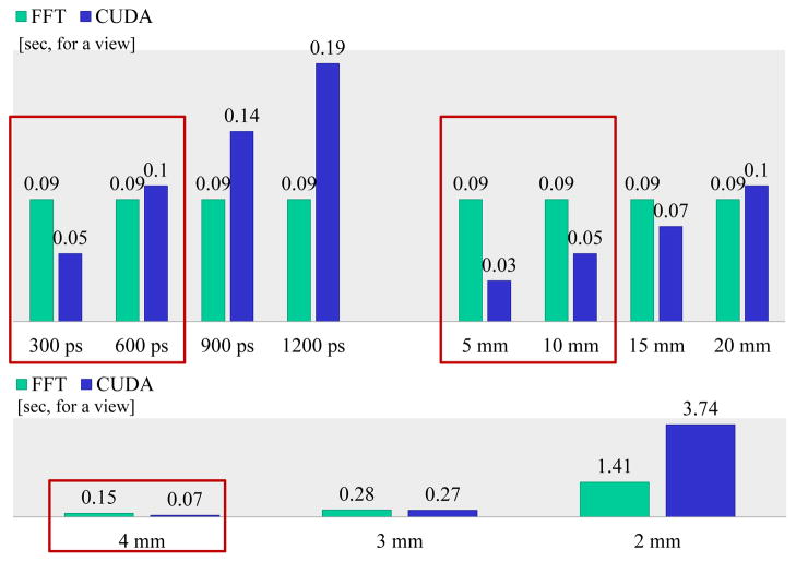
Fig. 4[top] shows the time performances with different SR kernel sizes. FFT-based approaches are generally attractive since their time performance is not affected by the SR kernel size, at least for a fixed grid size. This is not the case for the spatial-domain CUDA approach. However, we find that given the characteristics of modern PET scanners (600 ps and below), the CUDA approach in fact exhibits similar or faster time performance than the FFT-based one. Our study is based on clinical data and a resolution size representative of a state-of-the-art TOF scanner based on the LaBr3 detector [8][9].
Fig. 4.
Time performance for the FFT and the CUDA approach. [top] time performances for different SR kernel resolutions and for a fixed voxel size and dimension (4 mm3, 144 x 144 x 48); [top-left] varying TOF resolution (300 to 1200 ps FWHM) with fixed LOR resolution (10 mm and 5 mm radial and axial FWHM, respectively); [top-right] varying LOR resolution in the radial direction (5 to 20 mm FWHM) with fixed TOF (300 ps) and axial (5 mm) resolutions. [bottom] time performances for different voxel sizes (4 to 2 mm), and fixed SR kernel resolutions (375 ps FWHM for TOF and 6.5 mm for LOR) and voxel dimension (144 x 144 x 48). The red rectangle indicates configurations with parameter settings that are clinically practical.
Fig. 4[bottom] shows the effect of voxel size. Reducing the voxel size corresponds to an increase of the total number of voxels within the image, but at the same time it also leads to an increase of the number of voxels under the SR kernel. Both raise the computational demands of the space domain operations. For a reduction of voxel size from 4 to 2 mm, the number of operations for the space-based projection operations increases 23 x 23 = 64-times, while for the FFT-based approach the number of operations grows only by a factor close to 23 = 8-times, because the FFT approach performance is affected only by the image dimensions and not by the SR kernel size. In practice, the CUDA approach has a time increase slightly less than predicted – about a factor of 54.3 – for a 4 to 2mm voxel size reduction, while the FFT approach time grows by a factor of about 9.4. For 4mm voxels the CUDA approach is about twice as fast as the FFT approach, while for 2mm voxels it is about 2.7-times slower. However, it is crucial to realize that the CUDA approach can also efficiently handle projection operations with variant and/or asymmetric SR kernels (shown below), which is not possible with the FFT approach. This is the strength and motivation of our effort.
B. Accuracy tests of GPU forward and back-projectors
Figs. 5 and 6 show the projection results for three point sources with identical intensity values and placed along the y-axis in the same image slice but using different SR kernels. The color scale of these images has been carefully chosen to best show the structure. In the CUDA approach the SR kernel has been truncated to approximately three times of the kernel FWHM (±3σ) to minimize the SR kernel truncation errors. The maximum error between the two approaches is less than 1% of the maximum intensity value (Fig. 5a and b). With symmetric invariant SR kernels, there is no difference between the forward- and back-projections. The effects of the SR kernel truncation in the CUDA approach can be observed in the difference images in Fig. 5c. We observe elliptical boundaries where the CUDA approach drops to zero while the FFT approach still contains non-zero values (these effects are less than 0.48% of the maximum value). On the other hand, the truncation of the discretized SR kernel spectrum in the FFT approach causes small ripples (Gibbs artifacts) especially in the directions of the short kernel axes (LOR radial and axial directions) (Fig. 5c). Furthermore, for the extra-large SR kernels used in this example, we can also observe spatial aliasing effects in the FFT approach caused by the periodic nature of the discretized image in the FFT, leading to cyclic convolution. For example, in Fig. 5c [transverse view], the portion of the top of the SR kernel tail extending beyond (and truncated by) the top image boundary is leaking back into the bottom part of the image (from the periodic repeats of the image). To avoid such aliasing effects in the FFT approach, volume images can be padded with zeros before 3D-FFTs in the x, y and z directions. For a practical SR kernel and image sizes no or only a very small amount of zero-padding is usually needed.
Fig. 5.
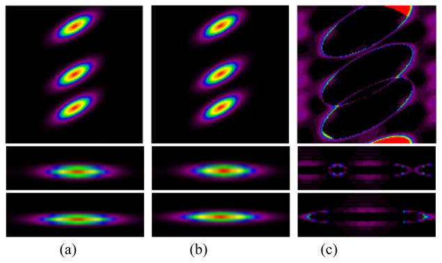
Comparison of the FFT and CUDA projector for the symmetric invariant case. The SR kernel has a 900 ps TOF resolution, and 50 mm and 10 mm LOR resolution in the radial and axial directions, respectively. (a) FFT (b) CUDA and (c) (FFT – CUDA) image. [top] transverse, [middle] sagittal and [bottom] coronal view. The sagittal and coronal views are zoomed-in to the center point source for better illustrations.
Fig. 6.
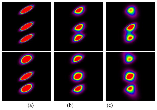
CUDA projector with generic SR kernel modeling. The SR kernels have 600 ps FWHM TOF resolution, and a LOR resolution of 10 to 80 mm (spatially variant) or 50 mm (spatially invariant) FWHM in the radial direction and 10 mm FWHM in the axial direction. (a) spatially variant symmetric (b) spatially invariant asymmetric and (c) spatially variant asymmetric. [top] forward projection and [bottom] back-projection.
But in practice, the SR kernels have different LOR resolutions depending on their radial locations. In the CUDA approach, such spatially varying SR kernels can be accurately modeled and applied to the projection operations. With symmetric (spatially) variant SR kernels, the results from forward- and back-projections are different, as shown in Fig. 6a. More specifically, with symmetric variant SR kernels each voxel has a particular SR kernel based on its radial location. Thus, the forward-projection spreads the intensity value at each point source to its neighbors and results in symmetric ellipsoid-like shapes, each having a different level of blurring (width) according to their radial distance from the central line of the projection (Fig. 6a [top]). In contrast, during back-projection, voxels at various radial distances from the projection center collect values from these same point sources but now the contributing SR kernels have different widths (narrower at locations radially closer to the center, and wider at locations radially closer to the FOV edge). This results in asymmetric elliptical shapes (wider towards the FOV edge, Fig. 6a [bottom])..
Lastly, we tested the CUDA code for forward- and back-projection with asymmetric invariant and variant SR kernels. To simulate asymmetric kernels the LOR resolutions in the radial direction are generated using the sum of two Gaussians in which one has twice the width. The wider Gaussian is shifted such that the sum can have a wider width on the side of the kernel towards the center of the FOV. With asymmetric and/or invariant SR kernels, we can observe different behaviors for forward- and back-projection operations which are by nature scatter and gather operations, respectively. For the forward-projection (Fig. 6b and c [top]), the results have an elongated response toward the FOV center, while during back-projection (Fig. 6b and c [bottom]) the elongated response is in the opposite direction. Especially with variant SR kernels, the elongation gets longer (or blurs more) as it goes closer to the edge of the FOV (Fig. 6c). We note that the large SR kernels used in these tests were not modeled based on real data—rather we sought to demonstrate the capability of our CUDA code to handle any generic SR kernel resolutions, which are difficult (if not impossible) to model with an FFT-based approach.
VI. Use of GPU Projectors Within DIRECT
In this section we test the performance of our CUDA forward- and back-projectors using both symmetric invariant (for comparison to the compatible FFT case) and symmetric variant SR kernels. The kernel parameters employed in this section are chosen to emulate (at various degrees) the characteristics of a state-of-the-art whole body TOF PET scanner.
A. Methods
We tested the DIRECT TOF PET reconstruction with two different projection approaches (FFT and CUDA), using measured data obtained from the University of Pennsylvania prototype whole body LaBr3 TOF-PET scanner [8][9]. This scanner has a 57.6 cm FOV, ±10° axial acceptance angle, with 4x4x30 mm3 LaBr3 crystals (and with 4.3 mm crystal pitch). The crystals are located within 24 detector flat modules, placed on a cylindrical detector surface of diameter 93 cm. The intrinsic spatial resolution of the scanner is about 5.8 mm and the timing resolution is approximately 375–430 ps (depending on the count rates). The measured data include attenuation, scatter and random events. The phantom object we used is a 35 cm diameter cylinder with clinically relevant volume and attenuation factors representative of a heavy patient. It contains six uniformly distributed 10 mm diameter spheres at radial positions of about 7.5 cm (from the center) which are placed in the central slice of the scanner. We acquired a relatively high number of counts (approximately 430M prompts) to enable us to see any differences between the approaches.
We use a block version of RAMLA (Row-Action Maximum Likelihood Algorithm). In DIRECT, we group and deposit events into 40 x 3 views: 40 intervals in azimuthal angle and 3 intervals in co-polar angle. Each view represents one block of RAMLA, giving us 120 updates for one pass through the data in the 40 x 3 view case. We employ TOF kernels representing 400 ps TOF resolution of measured data, and model spatially invariant and variant detector resolution kernels; the data deposition effects are not implicitly modeled in this particular study. The invariant LOR resolution kernel is applied for both approaches, FFT and CUDA, while the variant LOR resolution kernels are applied only in CUDA. The final image has a size of 144 x 144 x 48 with 4 mm3 voxels.
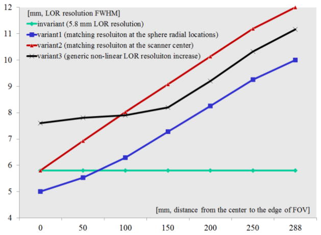
Fig. 7 shows the widths (FWHM) of the modeled detector LOR resolutions for both the invariant and the variant cases. For the invariant case, we use a 5.8mm FWHM LOR resolution over the entire FOV. We also model three variant kernels: (1) matching the LOR resolution at the center of the scanner (variant2), (2) matching the LOR resolution at the sphere locations at 7.5 cm radius (variant1), and (3) choosing a generic resolution functions varying with the radius in a non-linear fashion (variant3).
Fig. 7.
Models of the spatially invariant and variant detector resolutions. The variant detector resolutions are modeled to vary along the radial direction with different slopes.
We investigated the behavior of the variant and invariant resolution modeling in conjunction with iterative reconstruction, using the contrast versus noise trade-off for a range of iterations and reconstruction parameters. Contrast recovery coefficients (CRC) are calculated for all spheres as: CRC=((ps−pb)/pb)/c, where ps is the mean value in a 2D circular region of interest (ROI) axially and transversely centered over the sphere, pb is the mean background value in the 2D annular region surrounding and centered over each sphere, and c is the ideal contrast value. The reported CRC values are the average values over all 10 mm spheres in the phantom. The noise is evaluated as the pixel-to-pixel noise standard deviation inside a large 50 mm ROI located in the central uniform region of the phantom and normalized by the background mean value.
B. Reconstruction results
Table III shows the time performance for the invariant and variant SR kernels with the LOR widths based on the plots shown in Fig. 7. Similar to the evaluations of the projection operations, the CUDA implementation shows slightly faster or comparable time performance to the FFT for the invariant case. For the variant cases, the required time per iteration is slightly longer compared to the FFT invariant case. Note that for the variant SR kernels, the SR kernel’s physical (memory) size is defined by the longest LOR width, so the practical CUDA time performance is determined by the LOR resolution at the radial boundary of the FOV. The DIRECT iterative re-construction time includes all of the reconstruction stages such as reading the data, data transfers to and from the GPU, forward- and back-projection, and the discrepancy (computing the differences between the forward-projected and measured deposited data) and update (updating the image estimation) operators (Table IV). The forward- and back-projection operations still remain the bottleneck of the reconstruction process even if they are implemented on the GPU and were carefully optimized. The other operations take only about 10% (or less) of the total reconstruction time. According to Amdahl’s law which governs the speedup that can be obtained when only a fraction of the program is improved, the maximum possible speed-up is 1/(1−0.1)=1.1. It is therefore not beneficial to optimize and/or implement these operations on the GPU.
TABLE III.
Time performance comparison in DIRECT TOF PET reconstruction between FFT and CUDA
| Approach | FFT (single thread) | CUDA | |||
|---|---|---|---|---|---|
| LOR type at the edge [mm] | invariant 5.8 |
invariant 5.8 |
variant1 10 |
variant2 12 |
variant3 11.17 |
| 1 iteration [sec] | 21.48 | 15.63 | 22.43 | 25.66 | 24.68 |
TABLE IV.
Measured time at critical stage for invariant and variant1 cases with GPU in DIRECT TOF PET (20 iterations)
| [min:sec] | Forward-projection (GPU) | Discrepancy (CPU) | Back-projection (GPU) | Update (CPU) | Total | ||||
|---|---|---|---|---|---|---|---|---|---|
| H2D | FP | D2H | H2D | BP | D2H | ||||
| invariant | 0:7.53 | 1:45.27 | 0:2.85 | 0:0.32 | 0:7.59 | 1:43.18 | 0:2.85 | 0:12.59 | 5:11.97 |
| variant1 | 0:7.55 | 2:52.88 | 0:2.86 | 0:0.32 | 0:7.59 | 2:49.81 | 0:2.85 | 0:12.58 | 7:26.21 |
Note) H2D: data transfer from CPU to GPU, D2H: data transfer from GPU to CPU
Fig. 8[top] illustrates the contrast versus noise trade-off curves for DIRECT reconstructions using variant and invariant resolution models. Fig. 8[bottom] shows representative images of individual cases for matched noise levels (about 8%). It is clear from both the graphs and the visual image quality that the FFT and GPU approaches using invariant resolution models provide nearly identical results. In the spatially variant case (variant1 in Fig. 7), the CRC curve converges to slightly lower values compared to the invariant case. This is due to the fact that in the variant case the actually modeled LOR resolution at each particular sphere location changes with the projected view based on the radial distance of the sphere from the projection central line in each view. Thus, although this is a more accurate modeling, the average modeled resolution is actually lower than that in the invariant case, and this leads to a lower contrast values. For the other variant cases, having higher resolution models, the contrast converges to higher values. This is accompanied by increased overshoots (Gibbs artifacts) at the object boundaries (Fig. 8[bottom]), consistent with our previous experiences (as well as that of others) with the resolution modeling approaches.
Fig. 8.
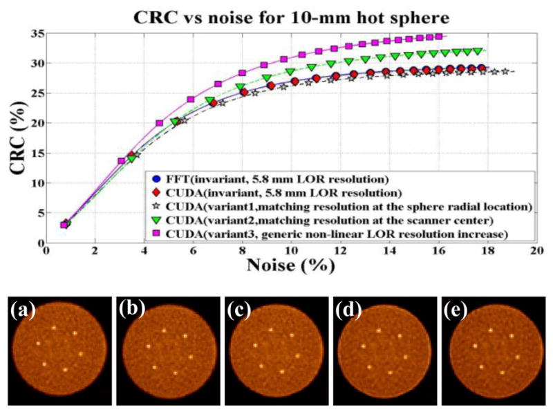
[top] CRC vs. Noise trade-off curves. [bottom] Reconstructed images (transverse view) at matched noise level (8%) (a) [ FFT] invariant SR kernel, (b) [CUDA] invariant SR kernel, (c) [CUDA] variant1, (d) [CUDA] variant2 and (e) [CUDA] variant3
VII. DISCUSSION
In the work conducted so far we did not compare our GPU-based schemes with equivalently optimized CPU implementations, both in terms of performance and in terms of accuracy. While this is planned for the future, it is unlikely that it will change the outcome and conclusions of our work.
First, it is doubtful that the performance of such a CPU-based scheme will match that of the GPU. This is because (for shift-invariant kernels) a CPU-based spatial convolution scheme will be naturally inferior to the more efficient divide-and-conquer strategy of an FFT-based implementation. On the other hand, our GPU-implementation is nearly on par, at least for problem sizes relevant to current clinical routine. In fact, we have observed this type of situation before in the context of exact CT reconstruction via the inverse Radon transform [20]. Then, modifying the shift-invariant CPU implementation to shift-variant kernels will incur similar performance losses than the modification of our GPU-accelerated scheme. Hence, the CPU implementation will still be significantly slower.
Second, when it comes to accuracy, with the emergence of GPU-based supercomputers employed for serious scientific simulations, GPUs have become as accurate as high-end CPUs. The recent NVIDIA Kepler GPU architecture fully complies with the IEEE 754 standard that governs single- and double-precision arithmetic. The work presented here has used a slightly older GPU which deviates from this standard in that some rounding modes as well as the NaN signal are not supported. But previous publications such as ours [11] have shown that even CT reconstructions obtained with much older GPU architectures were largely indistinguishable from their CPU-computed counterparts. Nevertheless, the GPU code that is the basis of the work presented here will trivially port to a Kepler GPU board and so honor the full IEEE standard.
VIII. Conclusion
We have implemented, optimized and evaluated an efficient framework for GPU-based forward- and back-projection operations (at any tilt and view direction) for the DIRECT TOF PET iterative reconstruction approach. Our framework is quite general and supports very generic system kernels, including both symmetric and asymmetric spatially (shift) variant and invariant kernels. We paid special attention to the memory access patterns for off-aligned axes in GPU memory and subsequently devised CUDA code that achieves a high level of performance by carefully balancing thread-level (TLP) and instruction-level (ILP) parallelism. Our GPU accelerated scheme is particularly relevant because it supports spatially variant and asymmetric kernels where algorithmically more efficient schemes based on the FFT cannot be used. It thus provides an important contribution to the PET reconstruction field since it allows for more accurate SR kernel modeling, particularly within the DIRECT iterative reconstruction framework without impeding clinical time performance.
Acknowledgments
This work was supported by NIH grant R01-EB-002131 and in part by NSF grants 1050477, 0959979 and 1117132.
Contributor Information
S. Ha, Email: sunha@cs.sunysb.edu, Center for Visual Computing, Computer Science Department, Stony Brook University, NY 11794 USA
S. Matej, Email: matej@mail.med.upenn.edu, Department of Radiology, University of Pennsylvania, Philadelphia, PA 19104 USA.
M. Ispiryan, Email: misp@mail.med.upenn.edu, Department of Radiology, University of Pennsylvania, Philadelphia, PA 19104 USA.
K. Mueller, Email: mueller@cs.sunysb.edu, Center for Visual Computing, Computer Science Department, Stony Brook University, NY 11794 USA.
References
- 1.Surti S, Karp J, Popescu L, Daube-Witherspoon M, Werner M. Investigation of time-of-flight benefit for fully 3-D PET. IEEE Trans Medical Imaging. 2006;25(5):529–538. doi: 10.1109/TMI.2006.871419. [DOI] [PubMed] [Google Scholar]
- 2.Conti M, Bendriem B, Casey M, Chen M, Kehren F, Michel C, Panin V. First experimental results of time-of-flight reconstruction on an LSO PET scanner. Phys Med Biol. 2005;50(19):4507–4526. doi: 10.1088/0031-9155/50/19/006. [DOI] [PubMed] [Google Scholar]
- 3.Watson C. An evaluation of image noise variance for time-of-flight PET. IEEE Trans Nuclear Science. 2007;54(5):1639–1647. [Google Scholar]
- 4.Karp J, Surti S, Daube-Witherspoon M, Muehllehner G. Benefit of time-of-flight in PET: Experimental and clinical results. J Nuclear Medicine. 2008;49(3):462–470. doi: 10.2967/jnumed.107.044834. [DOI] [PMC free article] [PubMed] [Google Scholar]
- 5.Matej S, Surti S, Jayanthi S, Daube-Witherspoon M, Lewitt R, Karp J. Efficient 3D TOF PET reconstruction using view-grouped histo-image: DIRECT-direct image reconstruction for TOF. IEEE Trans Medical Imaging. 2009;28(5):739–51. doi: 10.1109/TMI.2008.2012034. [DOI] [PMC free article] [PubMed] [Google Scholar]
- 6.Daube-Witherspoon M, Matej S, Werner M, Surti S, Karp J. Comparison of list-mode and DIRECT approaches for time-of-flight PET reconstruction. IEEE Trans Medical Imaging. 2012;31(7):1461–71. doi: 10.1109/TMI.2012.2190088. [DOI] [PMC free article] [PubMed] [Google Scholar]
- 7.Popescu L, Matej S, Lewitt R. Iterative image reconstruction using geometrically ordered subsets with list-mode data, “. IEEE Nuclear Science Symposium Conf Record. 2004;6:3536–3540. [Google Scholar]
- 8.Karp J, Kuhn A, Perkins A, et al. Characterization of a time-of-flight PET scanner based on lanthanum bromide. IEEE Nuclear Science Symposium Conf Record. 2005;4:23–29. [Google Scholar]
- 9.Daube-Witherspoon ME, Surti S, Perkins A, Kyba CCM, Wiener R, Werner ME, et al. The imaging performance of a LaBr3-based PET scanner. Phys Med Biol. 2010;55:45–64. doi: 10.1088/0031-9155/55/1/004. [DOI] [PMC free article] [PubMed] [Google Scholar]
- 10.Xu F, Mueller K. Accelerating popular tomographic reconstruction algorithm on commodity PC graphics hardware. IEEE Trans Nuclear Science. 2005;52(3):654–663. [Google Scholar]
- 11.Xu F, Mueller K. Real-time 3D computed tomographic reconstruction using commodity graphics hardware. Phys Med Biol. 2007;52(12):3405–3419. doi: 10.1088/0031-9155/52/12/006. [DOI] [PubMed] [Google Scholar]
- 12.Ha S, Zhang Z, Matej S, Mueller K. Efficiently GPU-accelerating long kernel convolutions in 3D DIRECT TOF PET reconstruction via a kernel decomposition scheme. IEEE Nuclear Science Symposium Conf Record. 2010:2866–2867. [Google Scholar]
- 13.NVIDIA Corporation. CUDA Programming Guide Version 40. 2011. [Google Scholar]
- 14.NVIDIA Corporation. NVIDIA GeForce GTX 200 GPU Architectural Overview. 2008 May; http://www.nvidia.com/docs/IO/55506/GeForce_GTX_200_GPU_Technical_Brief.pdf.
- 15.Bakhoda A, Yuan G, Fung W, Wong H, Aamodt T. Analyzing CUDA workloads using a detailed GPU simulator. IEEE ISPASS. 2009:163–174. [Google Scholar]
- 16.Pratx G, Xing L. GPU computing in medical physics: a review. Medical Physics. 2011;38(5):2685–2698. doi: 10.1118/1.3578605. [DOI] [PubMed] [Google Scholar]
- 17.Lo J, Emer J, Levy H, Stamm R, Tullsen D, Eggers S. Converting thread-level parallelism to instruction-level parallelism via simultaneous multithreading. ACM Trans Computing Systems. 1997;15(3):332–354. [Google Scholar]
- 18.Hakura Z, Gupta A. The design and analysis of a cache architecture for texture mapping. Proc Symp on Computer Architecture. 1997:108–120. [Google Scholar]
- 19.Frigo M, Johnson S. The design and implementation of FFTW3. Proceedings of the IEEE. 2005;93(2):216–231. [Google Scholar]
- 20.Neophytou N, Xu F, Mueller K. Hardware acceleration vs. algorithmic acceleration: Can GPU-based processing beat complexity optimization for CT?. SPIE Medical Imaging Conference; February 2007. [Google Scholar]


