Abstract
In this work, we conduct a computational study on the loading of cryoprotective agents into cells in preparation for cryopreservation. The advantages of microfluidics in cryopreserving cells include control of fluid flow parameters for reliable cryoprotectant loading and reproducible streamlined processing of samples. A 0.25 m long, three inlet T-junction microchannel serves as an idealized environment for this process. The flow field and concentration distribution are determined from a computational fluid dynamics study and cells are tracked as inert particles in a Lagrangian frame. These particles are not confined to streamlines but can migrate laterally due to the Segre-Sildeberg effect for particles in a shear flow. During this tracking, the local concentration field surrounding the cell is monitored. This data are used as input into the Kedem-Katchalsky equations to numerically study passive solute transport across the cell membrane. As a result of the laminar flow, each cell has a unique pathline in the flow field resulting in different residence times and a unique external concentration field along its path. However, in most previous studies, the effect of a spatially varying concentration field on the transport across the cell membrane is ignored. The dynamics of this process are investigated for a population of cells released from the inlet. Using dimensional analysis, we find a governing parameter α, which is the ratio of the time scale for membrane transport to the average residence time in the channel. For , cryoprotectant loading is completed to within 5% of the target concentration for all of the cells. However, for , we find the population of cells does not achieve complete loading and there is a distribution of intracellular cryoprotective agent concentration amongst the population. Further increasing α beyond a value of 2 leads to negligible cryoprotectant loading. These simulations on populations of cells may lead to improved microfluidic cryopreservation protocols where more consistent cryoprotective agent loading and freezing can be achieved, thus increasing cell survival.
INTRODUCTION
The cryopreservation of cells and tissues has become a practical way of storing biomaterials in a variety of disciplines and industries.1, 2, 3, 4, 5, 6 Cryopreservation is critical to long term storage and off-the-shelf availability.3, 7 Typical cryopreservation protocols aim to remove intracellular water to avoid damaging intracellular ice formation (IIF).8 This is usually accomplished by exposing the sample to a cryoprotective agent (CPA) to create an osmotic pressure gradient. These chemicals can be either permeable CPAs, which penetrate the cellular membrane and replace intracellular water, or impermeable CPAs, which dehydrate the cell by drawing out intracellular water.8 While CPAs are useful in preventing cell damage due to IIF, the dehydration process introduces cells to an osmolality gradient, inducing harmful osmotic shock.3, 9 Complicating the process further, the CPAs themselves can be toxic to cells.8, 10, 11
Two potential methods of cryopreservation are generally employed for cryopreservation: freezing and vitrification. The former uses lower CPA concentrations and slower cooling rates, which minimize osmotic shock and cytotoxicity effects, while being more susceptible to IIF. In the latter, high CPA concentrations are used with rapid cooling rates. This generally minimizes IIF at the expense of exposing the cell to potentially lethal osmostic gradients and toxic reagents. Since both methods require CPA loading and unloading, an understanding of the trans-membrane transport processes would be beneficial to optimizing protocols that would improve cell viability.
Mass transport of a non-electrolyte solute and the resulting water transport are typically modeled by the Kedem-Katchalsky (KK)12 equations. The equations for water flux and CPA flux across the membrane are given as:3, 9, 13, 14
| (1) |
| (2) |
| (3) |
| (4) |
| (5) |
In Eqs. 1, 2, 3, 4, 5, Jw and Jc are the water flux and cryoprotectant flux, respectively, Lp is the hydraulic conductivity, is the trans-membrane pressure gradient, σ is the CPA reflection coefficient, R is the universal gas constant, T is absolute temperature, is the trans-membrane concentration gradient, Vw and Vc are the water volume and cryoprotectant molality, respectively, A is the cell's surface area, ω is the CPA permeability through the membrane, and is the average of the internal and external CPA concentrations. Kleinhans provides an excellent review of these equations and when simplifications from the three parameter model to a two parameter model are appropriate.15
In traditional cryopreservation protocols, all cells are placed in a constant concentration for a prescribed time period. Due to the osmotic stresses and toxicity introduced to the cells, stepwise introduction of CPAs has been used; still, prescribed concentration and exposure time (along with any steps in concentration) are both known and constant for all cells. Modeling these scenarios has become fairly routine as Eqs. 1, 2, 3, 4, 5 are two coupled non-linear differential equations, which can be solved readily computationally. However, this could be further complicated by allowing a time dependent external cellular concentration (in the term). In an effort to account for the replacement time of a perfusion solution in their microdevice, Chen et al. have made the external concentration a time dependent term.16, 17 While a constant external concentration is valid for batch systems, it is not necessarily so for flow systems which have non-zero spatial concentration gradients due to incomplete mixing. Although a microdevice may operate at steady state, each cell will move through this device and encounter different extracellular concentrations as a function of time. While there has been a recent push to optimize cryopreservation protocols for survivability and throughput,2, 4, 11, 18 to optimize CPA loading in microfluidic devices, a more rigorous approach is necessary.
Microfluidic devices have been finding widespread utility in bioengineering and biomedical applications, including recent applications to CPA loading and unloading protocols. They offer reproducible, high-throughput analysis while minimizing sample volume and reagent consumption.19, 20 Microfluidic channels typically operate at Reynolds numbers (Eq. 6) on the order of unity and Peclet numbers (Eq. 7) on the order of 1000, indicating a lack of turbulence and that diffusion will be a relatively slow process compared to convection through the channel
| (6) |
| (7) |
In Eqs. 6, 7, u, w, ρ, μ, and Dab are the characteristic velocity, distance, density, viscosity, and mass diffusivity of the system. The resulting lack of mixing in high Peclet number, convection dominated environments, has often been lamented as a pitfall of lab-on-a-chip devices. A variety of micromixers have been developed to overcome this problem and its associated challenges.21, 22, 23, 24, 25 However, the laminar flow in microdevices has also been used advantageously. Spherical particles in laminar shear flow experience a lift force, which causes them to migrate to an equilibrium position. This is known as the Segre and Silberberg effect.26 The effect is observed in long channels, and the magnitude of this force is dependent on the particle Reynolds number. It has been used in microchannels as a means for particle separation based on size.27
Recent work on cryoprotectant loading and unloading on a chip has also used the lack of turbulence in microdevices to their advantage, where the lack of fluid mixing allows a slow introduction of CPA to the cell.9, 10, 18, 28, 29, 30, 31, 32 Song et al.9 have shown that the gradual loading of CPA into the cell improves cell survival compared to traditional methods. They argue the less dramatic water flux across the membrane is responsible for the improved cell viability by limiting osmotic shock. The application of microfluidics to the CPA loading process also meets the needs cited by researchers in the cryopreservation field, namely, the ability to create high-throughput, readily reproducible, and streamlined processes needed in research and industry.2, 4, 6 With a stable of advantages and the decreasing cost of device fabrication, microfluidic devices have the potential to become commonplace in cryopreservation protocols.
Previous modeling work on CPA loading in microfluidic devices has been devoid of discrete cells traveling throughout the channel. The concentration along a single streamline has been input into the external concentration9 for CPA loading, and a CPA source/sink term (depending on whether CPA is entering or exiting the cell) has been included in the species transport equation.28, 29, 30 The former does not capture the true trajectory of a single cell, which will experience forces due to the shear flow in the long microchannel; the latter does not monitor the changes in volume or internal concentration among the cells. Neither of these methods capture the dynamics across a population of cells, which will have a distribution of residence times as well as external concentration profiles. Furthermore, the utilization of constant fluid properties in the previous simulations could be a source for error, especially given the disparity between the viscosities of common CPAs and water.
Prior to their modeling, Song et al.9 made the KK equations dimensionless and they arrive at a characteristic time, t0, for transport across the membrane
| (8) |
It is important to note that t/t0 equal to one does not mean that the transport process across the membrane has reached equilibrium; in batch processes (where the extracellular concentration is maintained at C0) this occurs around t/t0 of between 5 and 6. The residence time is a natural time scale for convection in a microchannel,
| (9) |
Taking the ratio of these two time scales allows us to determine the relative magnitude of each process (analogous to the Peclet number as the ratio of convection to diffusion). This results in
| (10) |
If , we expect complete CPA loading; for we expect the cells will move through the channel faster than any appreciable loading can take place; for (t0 is a characteristic time scale, but not the time for the process to complete as noted earlier) we expect a distribution of intracellular CPA concentration where loading will be appreciable but incomplete.
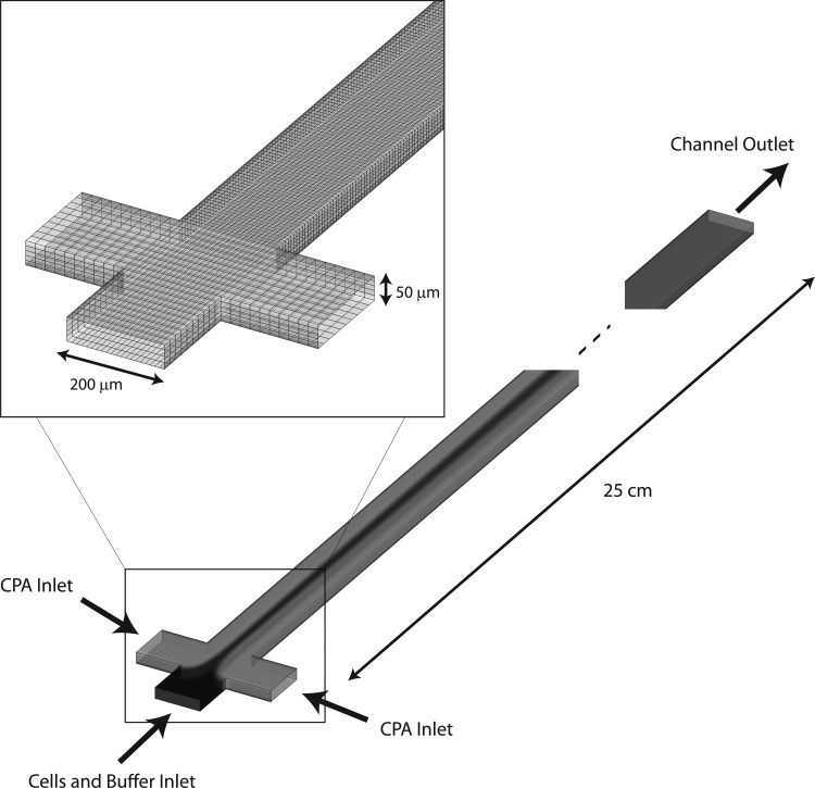
In this work, we simulate the loading of 1,2-propanediol (a common cryoprotectant agent) across an idealized cell membrane in a T-channel. Fig. 1 shows a schematic of the simulated device. This microchannel could easily be folded into a serpentine-like geometry to minimize the chip footprint.9 However, the 0.25 m pathlength is necessary to provide adequate residence time for membrane transport to occur and the cells to reach equilibrium with their environment. Two possibilities exist for extending the residence time in the channel: (1) decreasing the Reynolds number, or (2) increasing the channel length. Since the latter is not ideal in microfluidics where chip footprint is paramount (and to maintain sufficient accuracy in a long simulation domain), in this work, we investigate the membrane transport over a range of flow rates in a channel of fixed length.
Figure 1.
The three inlet T-Channel simulation geometry. The inset highlights the mesh resolution at the junction of the three inlets.
METHODS
Fluid flow modeling
The computational fluid dynamics package ansys fluent v13 (Ansys, Inc., Canonsburg, PA) was used to solve the steady state continuity, conservation of momentum, and species continuity (Eqs. 11, 12, 13, 14) using the finite volume method
| (11) |
| (12) |
| (13) |
| (14) |
| (15) |
In Eqs. 11, 12, 13, 14: u is the fluid velocity, ρ is the fluid density, μ is the fluid viscosity, Ci is the concentration of species i, and Dab is the mass diffusivity. Local fluid properties of the CPA-water mixture were calculated by mass averaging the local density and viscosity in each finite volume element. The diffusivity of propanediol in water was calculated using a modified Wilke-Chang equation33
| (16) |
In Eq. 16, D12 is the local mass diffusivity, M1 is the molecular weight of the solvent, T is the absolute temperature, V1 is the molal volume of solvent, V2 is the molal volume of solute, and is the local viscosity of the mixture.
The boundary conditions for the Navier-Stokes equations were specified as the same constant normal velocity at all three inlets and zero pressure at the outlet. The no-slip boundary condition was specified at all walls. For the species continuity equation, constant inlet concentrations were specified for the sample and sheath inlets. A convective flux condition was specified at the outlet, with a zero flux boundary condition specified on the walls.
Particle tracking
Lagrangian particle tracking was used in fluent to simulate cells as inert spherical particles inside the channel. Once the steady state flow field is solved in the domain, spherical particles are released from each finite volume face on the center inlet. The position and velocity of the particles as they progress through the microdevice are calculated via a force balance on the particles,
| (17) |
| (18) |
| (19) |
| (20) |
In Eqs. 17, 18, 19, 20, FD is the drag force on the particle, uf is the fluid velocity, up is the particle velocity, g is the acceleration due to gravity, is the particle density, is the fluid density, F is the Saffman lift force due to shear, CD is the drag coefficient for smooth and spherical particles, Rep is the particle Reynolds number, dp is the particle diameter, K is a constant coefficient of Saffman's lift force (and is set to 2.594), ν is the fluid kinematic viscosity, and dij is the deformation tensor.
Particles are released from each face of the sample inlet and the particle tracking continues for each particle until they exit the channel. One-way steady coupling was used between the discrete phase and the continuous phase (the discrete phase was assumed to cause negligible disturbances on the dynamics of the continuous phase). The particles used in the Lagrangian tracking are point particles; a particle diameter and density are specified to solve the force balance equations, but the particles do not occupy a physical space and hence they are allowed to overlap. Particle-particle interactions (collisions, drafting) are not included in this work. The particle time-step was controlled using a custom user-defined function in fluent that allowed a maximum particle time step of 0.001 s. This was done to maintain accuracy during the particle position integration, as well as providing a sufficient number of concentration data points as inputs into the KK equations. As each particle progresses through the domain, the local CPA concentration of each particle is recorded at each time step.
Membrane transport modeling
After fluid flow and particle tracking simulations are complete, the transient local CPA concentration data for each particle is imported into matlab (MathWorks, Natick, MA). As previously discussed, membrane permeability to non-electrolytes is modeled by the Kedem-Katchalsky equations, Eqs. 1, 2, 3, 4; in this work, these equations are solved numerically using a 4th order Runge-Kutta scheme. While our model captures water efflux out of the cell, the dilution of the local external concentration around each cell is assumed to be negligible. The cellular density is assumed to be constant; that is, removal of water and introduction of CPA does not change the density used in Eqs. 17, 18. Table TABLE I. shows the parameters used in these equations.
TABLE I.
Model parameters for the Kedem-Katchalsky equations9 and fluid dynamics equations.
| Parameter | Value |
|---|---|
| Initial cell diameter, | |
| Hydraulic conductivity, Lp | |
| Permeability, ω | (kmol/N s) |
| Reflection coefficient, σ | 0.8 |
| Particle (cell) density, | 1030 (kg/m3) |
| CPA density, | 1036 (kg/m3) |
| CPA viscosity, | 0.0404 (Pa s) |
| Water density, | 998 (kg/m3) |
| Water viscosity, | 0.001 (Pa s) |
We study the importance of the relative time for membrane mass transport and transport of the cell from inlet to outlet. In this work, our models are tested over a range of α from 0.05 to 10. Select times and parameters for Eq. 10 are shown in Table TABLE II..
TABLE II.
The range of α's tested.
| Flow rate (μl/min) | C0 (mol/l) | (s) | (s) | |
|---|---|---|---|---|
| 0.05 | 1 | 9998 | 112.3 | 0.112 |
| 0.1 | 1 | 499 | 112.3 | 0.2246 |
| 1 | 1 | 49.9 | 112.3 | 2.246 |
| 10 | 1 | 4.999 | 112.3 | 22.46 |
RESULTS
Simulation validation
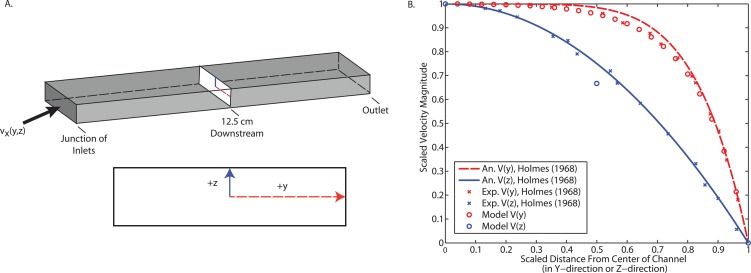
Accurately capturing the fluid flow and mass transport in the microchannel are critical in modeling the mass transport across the membrane. In Fig. 2, we compare our results to an analytical expression and experimental data for the velocity profile in a rectangular duct. This validation study uses the same geometry and mesh as in the remainder of our studies, but with pure water entering each of the inlets. The analytical expression34
| (21) |
is an empirical approximation of the more rigorous solution for laminar flow in a rectangular duct. Here, ξ and ζ are scaled distances in the y and z directions, respectively, and m and n are empirically determined coefficients that depend on the aspect ratio of the rectangular duct. We achieve excellent agreement with both the analytical expression and the experimental results, indicating that our model can capture the fluid flow accurately.
Figure 2.
Comparing the velocity magnitudes of this fluid dynamics model with pure water at all inlets to analytical and experimental data. (a) A schematic of the geometry and the cross-sections where velocity was evaluated. (b) Scaled velocity magnitude as a function of scaled y-position and scaled z-position for an analytical expression for fluid flow in a rectangular duct, experimental results, and this model.
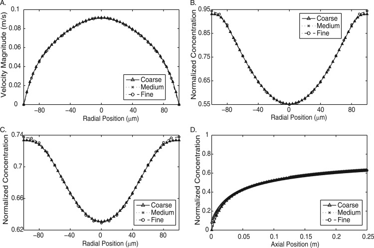
We perform mesh dependence studies to determine the effect of changing the mesh resolution. These tests were performed at several inlet flow rates, with CPA entering from the sheath inlets and water entering from the sample inlet. The numerical methods are expected to exhibit a greater degree of mesh dependency at higher Peclet numbers. The results in Fig. 3 show the effect of mesh resolution at the highest Peclet number tested in this work. Both the velocity profile and concentration profiles in multiple directions show negligible differences. We find that our fluid flow simulations are sufficiently resolved so as to be mesh independent.
Figure 3.
Mesh dependence test of three meshes at the highest flow rate evaluated. Coarse = 4 788 966 elements; Mid= 5 745 246 elements; Fine = 6 303 966 elements. (a) Velocity magnitude cross-section at a distance of 0.125 cm downstream from the junction of the inlets. (b) Concentration cross-section at a distance of 0.125 cm downstream from the junction of the inlets. (c) Concentration cross-section at the outlet. (d) Concentration profile along the axial length of the channel.
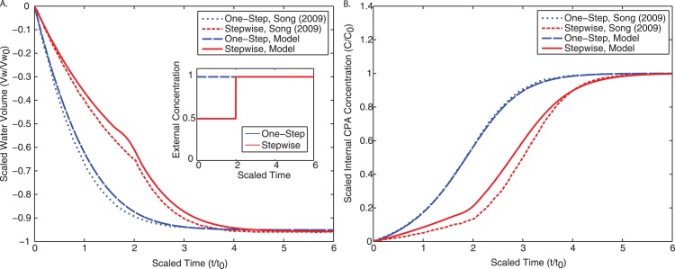
A final validation of this approach was to test the implementation of the Kedem-Katchalsky equations by comparing to results from the literature.9 For one-step CPA loading (shown in Fig. 4a), all cells are exposed to a normalized concentration of for a normalized time of . For stepwise CPA loading (shown in Fig. 4b), the scaled external CPA concentration is set at for a time of and then raised to for an additional (inset of Fig. 4a). Our results match well for both cases and we can conclude that our model will successfully capture the dynamics of membrane transport.
Figure 4.
Comparison of our implementation of the KK equations to Song9 for both one-step loading (cells exposed to for a time of ) and stepwise loading (cells exposed to for a time of , and then to for an additional ). (a) Normalized intracellular water volume as a function of normalized time. The inset describes the transient external CPA concentration to which the cells were exposed. (b) Normalized intracellular CPA concentration as a function of normalized time.
Varying fluid and mass transport properties
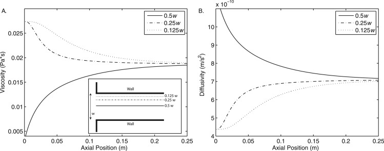
With a water-based buffer solution entering the sample inlet and 1.5 mol/l propanediol entering the side inlets, the viscosity ratio is close to 40:1. As the two miscible streams begin to mix, the viscosity of the mixture changes as illustrated in Fig. 5a. Since diffusion is hindered by the more viscous liquid, as the fluids mix, the diffusivity of the mixture also changes (Fig. 5b). These complex, local changes in fluid properties are determined by the flow field itself and are accounted for in the simulation using mixing rules, based on local concentrations.
Figure 5.
Varying fluid viscosity as a function of axial position in the microchannel. Data are taken along three parallel lines spanning the length of the channel from the junction of the inlets to the outlet. In the transverse direction, these lines correspond to one-half, one-quarter, and one-eighth of the channel width.
In Fig. 5, the viscosity and the diffusivity approach their respective well-mixed values by the end of the channel. Since viscosity (and by Eq. 16, diffusivity as well) are functions of the local propanediol concentration, this indicates that at 10 μl/min the solution has reached a nearly homogeneous state in the middle 75% of the channel. These plots are for the highest inlet flow rates tested in this work; lower inlet flow rates become uniformly mixed closer to the inlet.
Dynamic particle data
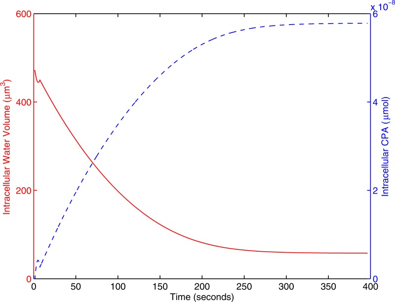
When the cells encounter an osmotic gradient, intracellular water exits the cell. If the external solute causing the osmotic gradient is permeable, it will enter the cell. The increase in intracelluar solute, coupled with the decrease in intracellular solvent both increase the internal CPA concentration. This behavior is shown in Fig. 6.
Figure 6.
The transient behavior of a single cell at . Water exits the cell while CPA enters. The solid red line represents intracellular water volume; the dashed line represents intracellular moles of CPA.
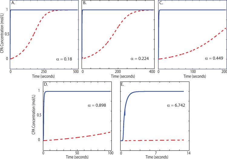
One key advantage of numerical modeling over experimental data is the ability to simultaneously probe the dynamic behavior of every cell as they move throughout the microchannel. Since experimental work has shown that this loading is within the osmotic tolerance of the cells,9 in this work, we focus particularly on the distribution of internal concentration rather than cell volume. The response of cell volume to anisosmotic conditions has been extensively studied and verified using experimental approaches.35 Since internal CPA concentrations are obviously more difficult to measure directly, the modeling approach can yield insight. Fig. 7 shows the same cell's intracellular and extracellular concentration as a function of its time throughout the device for different α values. The target loading of this cell was 1 mol/l, which is met at different residence times throughout the mixer depending on the inlet flow rate. In Fig. 7, lower α values have larger residence times (the x-axis). This affords the membrane transport process enough time to complete, as seen at α's of 0.18 and 0.224 (Figs. 7a, 7b). For this particular cell of the population, Fig. 7b shows the transport process takes approximately the full residence time to complete (). As the flow rate increases, corresponding to an increase in α, the residence time decreases. This cell only loads to 20% of its target concentration for α = 0.898. At α = 6.742, the internal CPA concentration is negligible for this cell at the channel outlet.
Figure 7.
Transient concentration profiles for one representative particle out of the 250 particles tracked. The solid line showsthe extracellular CPA concentration; the dashed line shows the intracellular CPA concentration. Each plot displays a different value of α, showing how this parameter changes the final CPA loading. As α increases, the loading moves further from completion. The α values correspond to flow rates of: (a) 0.08 μl/min, (b) 0.1 μl/min, (c) 0.2 μl/min, (d) 0.4 μl/min, and (e) 3 μl/min.
Fig. 7 also shows how changing α can change how a flow system is modeled. For the lower values of α, mixing by molecular diffusion occurs in such a relatively short length down the channel that the cell experiences a constant external concentration for almost its entire residence time. Only in this limit, modeling the membrane transport process as a batch system held at a constant external concentration would be valid.
Cell population results
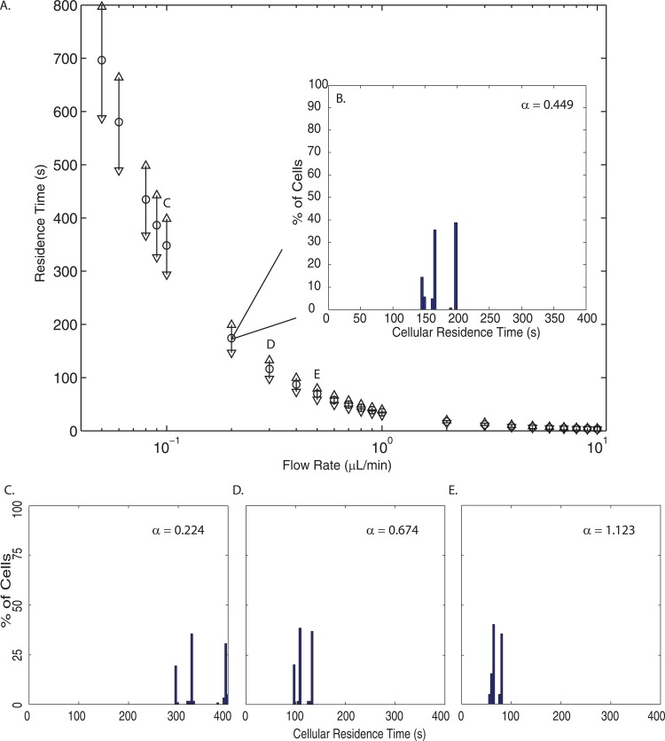
The dynamic data were analyzed for each individual cell released from the inlet. While this information is useful for understanding each cells' experience as they pass through the microchannel, histograms provide information on the population of cells once they exit. Fig. 8a shows the cellular residence time distribution at each flow rate: , and ▽ represent the mean, maximum, and minimum residence time, respectively. Panels B-E in Fig. 8 show the histograms associated with selected flow rates. Slower flow rates have larger residence times and the deviation from the mean increases as flow rate decreases; at higher flow rates, particles exit the channel closer in magnitude to the mean.
Figure 8.
(a) The cellular residence time distributions over the entire cell population for each flow rate simulated. The ○ indicates the mean residence time, while the △ represents the maximum residence time, and the ▽ shows the minimum residence time. (b) A histogram of the cellular residence times at 0.2 μl/min (). (c)-(e) Histograms of cellular residence times at 0.1 μl/min (), 0.3 μl/min (), and 0.5 μl/min (), respectively.
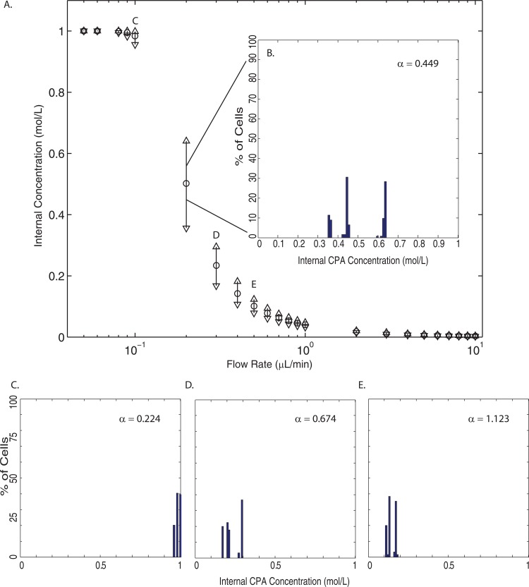
Fig. 9a shows the distribution of the cells' internal concentration when they reach the channel outlet for each flow rate; panels B-E show the histograms associated with selected flow rates. Again, the ○ indicates the mean internal concentration, △ represents the maximum internal concentration, and the ▽ shows the minimum internal concentration. Fig. 9 clearly shows three regimes: complete loading, incomplete loading, and negligible loading. These correspond to , and . As expected by the scaling, when t0 (the characteristic time for membrane transport) is much less than τ (the cell's residence time), the cell exits the channel before CPA loading can begin. If τ is smaller than t0, the CPA has enough time to make it across the cell membrane. When these two times are comparable, the cell will not complete loading.
Figure 9.
(a) The internal concentration distributions over the entire cell population for each flow rate simulated. The ○ indicates the mean internal concentration, while the △ represents the maximum internal concentration, and the ▽ shows the minimum internal concentration. (b) A histogram of the internal concentration at 0.2 μl/min (). (c)-(e) Histograms of internal concentrations at 0.1 μl/min (), 0.3 μl/min (), and 0.5 μl/min (), respectively.
The larger internal concentration distributions also occur in this incomplete loading regime. At higher α values, there is a small deviation in cell residence times and all cells have a residence time sufficiently small for negligible loading. With small α, Fig. 8 shows that there are large distributions in residence time. However, even the smallest residence time (within the complete loading regime) is still large enough for the membrane transport process to complete. When these two processes are on the same order, in this incomplete loading regime, there will be a larger distribution of internal CPA concentration across the population of cells. In our study, we found the largest internal concentration distribution to occur at a flow rate of 0.2 μl/min ().
CONCLUSIONS
Cryoprotectant loading and unloading are necessary steps in the cryopreservation process. The removal of intracellular water is critical in elimination of intracellular ice formation, which is lethal to cells during freezing. Historically, this loading has been a batch process where the external cryoprotectant concentration remained constant. Microfluidics has recently been shown to provide gradual loading which is thought to minimize osmotic shock and increase post-freeze viability.9, 18 In this work, we have numerically investigated the effect of laminar shear flow on the distribution of cryoprotectant loading across a population of cells in a microchannel. The parabolic velocity profile ensures a distribution of cellular residence times in the channel. Since each cell has a different residence time and path through the channel, the transient external environment varies across the population of cells. This results in a distribution of internal CPA concentration.
The fluid and transport properties have been resolved to reflect the disparity between the two miscible liquids, specifically their viscosities. In our simulations, viscosity and density for the mixture are weighted by the local concentration of propanediol. More viscous liquids should provide greater resistance to diffusion, which was accounted for by a modified Wilke-Chang equation in our model. We have used Lagrangian tracking with inert spherical particles to represent idealized cells. The Kedem-Ketchalsky equations were then solved with the time-varying external concentration for each cell.
Appropriate time scales for both convection through the microchannel and transport across the cell membrane were chosen. The ratio of the two provides insight into which process is dominant, and when the two are comparable. When , cells are carried through the microchannel slow enough that cryoprotectant transport has time to complete in all cells. For large values of α, transmembrane transport is slower than convection and CPA loading is incomplete. Incomplete loading and distributions of intracellular CPA concentration occur when .
While lower flow rates () provide complete CPA loading, their loading profiles begin to approach that of a batch process with a constant concentration for the majority of the cell's residence time. At low enough flow rates, molecular diffusion completely mixes the two fluids a short distance down the channel. As α increases, the transient external concentration of a batch process and the microfluidic process grow increasingly different. This has significant ramifications on cell viability. Song et al.9 showed that microfluidic loading resulted in higher cell survival rates than both one-step and stepwise CPA loading (both batch processes). They argued that the water flux and CPA flux profiles were less pronounced, and this resulted in a smaller degree of osmotic shock. Combining this with our results, we can see that to experience these benefits of progressive loading (smaller fluxes resulting in improved viability), operating at the lower values of α are ill-suited because the dynamics of loading for each individual cell more closely resembles a batch system. In addition, modeling in the low α range can be simplified: cells can be modeled with a constant external concentration, but with each cell having a unique residence time. The particle tracking is still necessary, but the additional computational effort required for the dynamic external CPA concentration can be removed.
Our model has several distinct advantages over previous modeling efforts of CPA loading in a microchannel. Other simulations do not include discrete particles (cells); they either account for the varying concentration by following a streamline, or they lump the cells together and add a source/sink term to the species continuity equation. While the former can then use a transient concentration as input, cells in a shear flow will migrate across streamlines in long enough channels. This will result in an inaccurate transient concentration profile, as well as an inaccurate residence time (as cells migrate further from the center of the channel, they will have a slower velocity). The latter is capable of simulating the removal of CPA from the microchannel fluid to the cells (for CPA loading), or addition of CPA to the microchannel fluid by the cells (in the case of CPA unloading). However, this is captured by a bulk source/sink term to the species continuity equation and since no cells are included in this modeling, the dynamics inside each cell are not observed. Modeling discrete cells using Lagrangian particle tracking could be of use in device design as well, where cell separation and recovery is dependent on channel geometry and operating conditions.30, 31, 32, 36
The simulations presented herein also include the effect of a parabolic velocity profile in three dimensions that the cells are initially evenly distributed across. Ramifications of this inclusion are two-fold: (1) all cells do not have the same residence time, and (2) all cells do not experience the same external CPA concentration throughout their residence time. This directly affects the dynamics of CPA loading for each cell of the population. Finally, previous modeling efforts have treated fluid properties as constants despite most common CPAs being much more viscous than water. Our model captures the spatially varying density, viscosity, and CPA diffusivity. Unlike other modeling work in the literature, this has the potential to model the more complex interactions of multiple CPAs inside a microchannel, as in CPA cocktails.
Other pioneering work has been done to show the potential of microfluidics in the field of cryopreservation; this current work has shown that special care must be taken in choosing operating conditions.9, 10, 18, 28 We have shown that an analysis on a population of cells is possible and modeling can be done to avoid intracellular CPA distributions and incomplete loading, which could lead to large variability in cell freezing behavior and thus survival. Given that osmotic tolerances and CPA toxicity levels are known for many cell types, our model provides a method for a further understanding of cell viability during CPA loading and unloading. In our model we calculate cell volume, internal concentration, and residence time of every cell as it moves throughout the microchannel. Since lethal osmotic shock can be quantified by monitoring cell volume, and since CPA toxicity is a function of the CPA concentration and the exposure time, our model provides a framework for comparing the relative magnitudes of each cause of cell death during CPA loading. In the future we intend to apply our model to other microsystems with spatially varying concentration fields where cell outcomes are dictated by membrane transport.
ACKNOWLEDGMENTS
The authors wish to acknowledge the High Performance Computing Center at Louisiana State University. Thomas Scherr is supported by the Computational Fluid Dynamics NSF-IGERT program at Louisiana State University, the Donald W. Clayton Fellowship at Louisiana State University, and a Coates Research Grant at Louisiana State University. Shelby Pursley would like to acknowledge the Chancellor's Future Leaders in Research program at Louisiana State University.
References
- Lane M., Bavister B. D., Lyons E. A., and Forest K. T., Nat. Biotechnol. 17, 1234 (1999). 10.1038/70795 [DOI] [PubMed] [Google Scholar]
- Hu E., Yang H. P., and Tiersch T. R., Cryobiology 62, 74 (2011). 10.1016/j.cryobiol.2010.12.006 [DOI] [PMC free article] [PubMed] [Google Scholar]
- Cui Z. F., Dykhuizen R. C., Nerem R. M., and Sembanis A., Biotechnol. Prog. 18, 354 (2002). 10.1021/bp0101886 [DOI] [PubMed] [Google Scholar]
- Tiersch T. R., Yang H., and Hu E., Comp. Biochem. Physiol., Part C: Toxicol. Pharmacol. 155, 49 (2012). 10.1016/j.cbpc.2011.08.007 [DOI] [PubMed] [Google Scholar]
- Thirumala S., Gimble J. M., and Devireddy R. V., Biotechnol. Bioeng. 92, 372 (2005). 10.1002/bit.20615 [DOI] [PubMed] [Google Scholar]
- Yang H. P., Norris M., Winn R., and Tiersch T. R., Cryobiology 61, 211 (2010). 10.1016/j.cryobiol.2010.07.006 [DOI] [PMC free article] [PubMed] [Google Scholar]
- Lawson A., Mukherjee I. N., and Sambanis A., Cryobiology 64, 1 (2012). 10.1016/j.cryobiol.2011.11.006 [DOI] [PMC free article] [PubMed] [Google Scholar]
- Guha A. and Devireddy R., Ann. Biomed. Eng. 38, 1826 (2010). 10.1007/s10439-010-9963-z [DOI] [PubMed] [Google Scholar]
- Song Y. S., Moon S., Hulli L., Hasan S. K., Kayaalp E., and Demirci U., Lab Chip 9, 1874 (2009). 10.1039/b823062e [DOI] [PMC free article] [PubMed] [Google Scholar]
- Park S., Wijethunga P. A. L., Moon H., and Han B., Lab Chip 11, 2212 (2011). 10.1039/c1lc20111e [DOI] [PMC free article] [PubMed] [Google Scholar]
- Benson J. D., Kearsley A. J., and Higgins A. Z., Cryobiology 64, 144 (2012). 10.1016/j.cryobiol.2012.01.001 [DOI] [PubMed] [Google Scholar]
- Kedem O. and Katchalsky A., J. Gen. Physiol. 45, 143 (1961). 10.1085/jgp.45.1.143 [DOI] [PMC free article] [PubMed] [Google Scholar]
- Xu F., Moon S., Zhang X., Shao L., Song Y. S., and Demirci U., Philos. Trans. R. Soc. London 368, 561 (2010). 10.1098/rsta.2009.0248 [DOI] [PMC free article] [PubMed] [Google Scholar]
- Li L. Y., Comput. Mater. Sci. 35, 75 (2006). 10.1016/j.commatsci.2005.03.006 [DOI] [Google Scholar]
- Kleinhans F. W., Cryobiology 37, 271 (1998). 10.1006/cryo.1998.2135 [DOI] [PubMed] [Google Scholar]
- Chen H. H., Purtteman J. J. P., Heimfeld S., Folch A., and Gao D., Cryobiology 55, 200 (2007). 10.1016/j.cryobiol.2007.08.001 [DOI] [PubMed] [Google Scholar]
- Chen H. H., Shen H., Heimfeld S., Tran K. K., Reems J., Folch A., and Gao D. Y., Int. J. Heat Mass Transfer 51, 5687 (2008). 10.1016/j.ijheatmasstransfer.2008.04.013 [DOI] [Google Scholar]
- Heo Y. S., Lee H. J., Hassell B. A., Irimia D., Toth T. L., Elmoazzen H., and Toner M., Lab Chip 11, 3530 (2011). 10.1039/c1lc20377k [DOI] [PMC free article] [PubMed] [Google Scholar]
- Squires T. M. and Quake S. R., Rev. Mod. Phys. 77, 977 (2005). 10.1103/RevModPhys.77.977 [DOI] [Google Scholar]
- Whitesides G. M., Nature 442, 368 (2006). 10.1038/nature05058 [DOI] [PubMed] [Google Scholar]
- Stroock A. D., Dertinger S. K. W., Ajdari A., Mezic I., Stone H. A., and Whitesides G. M., Science 295, 647 (2002). 10.1126/science.1066238 [DOI] [PubMed] [Google Scholar]
- Scherr T., Quitadamo C., Tesvich P., Park D. S. W., Tiersch T., Hayes D., Choi J. W., Nandakumar K., and Monroe W. T., J. Micromech. Microeng. 22, 055019 (2012). 10.1088/0960-1317/22/5/055019 [DOI] [PMC free article] [PubMed] [Google Scholar]
- Park D. S., Egnatchik R. A., Bordelon H., Tiersch T. R., and Monroe W. T., Theriogenology 78, 334 (2012). 10.1016/j.theriogenology.2012.02.008 [DOI] [PMC free article] [PubMed] [Google Scholar]
- Nguyen N. T. and Wu Z. G., J. Micromech. Microeng. 15, R1 (2005). 10.1088/0960-1317/15/2/R01 [DOI] [Google Scholar]
- Sudarsan A. P. and Ugaz V. M., Lab Chip 6, 74 (2006). 10.1039/b511524h [DOI] [PubMed] [Google Scholar]
- Segre G. and Silberberg A., Nature 189, 209 (1961). 10.1038/189209a0 [DOI] [Google Scholar]
- Bhagat A. A. S., Kuntaegowdanahalli S. S., and Papautsky I., Microfluid. Nanofluid. 7, 217 (2009). 10.1007/s10404-008-0377-2 [DOI] [Google Scholar]
- Fleming K. K., Longmire E. K., and Hubel A., J. Biomech. Eng. 129, 703 (2007). 10.1115/1.2768373 [DOI] [PubMed] [Google Scholar]
- Fleming Glass K. K., Longmire E. K., and Hubel A., Int. J. Heat Mass Transfer 51, 5749 (2008). 10.1016/j.ijheatmasstransfer.2008.04.018 [DOI] [PMC free article] [PubMed] [Google Scholar]
- Hanna J., Hubel A., and Lemke E., Biotechnol. Bioeng. 109, 2316 (2012). 10.1002/bit.24499 [DOI] [PMC free article] [PubMed] [Google Scholar]
- Bala Chandran R., Reinhart J., Lemke E., and Hubel A., Biomicrofluidics 6, 044110 (2012). 10.1063/1.4767463 [DOI] [PMC free article] [PubMed] [Google Scholar]
- Mata C., Longmire E. K., McKenna D. H., Glass K. K., and Hubel A., Microfluid. Nanofluid 5, 529 (2008). 10.1007/s10404-008-0265-9 [DOI] [PMC free article] [PubMed] [Google Scholar]
- Reddy K. A. and Doraiswamy L. K., Ind. Eng. Chem. Fundam. 6, 77 (1967). 10.1021/i160021a012 [DOI] [Google Scholar]
- Holmes D. B. and Vermeulen J. R., Chem. Eng. Sci. 23, 717 (1968). 10.1016/0009-2509(68)85006-7 [DOI] [Google Scholar]
- McGrath J. J., Cryobiology 34, 315 (1997). 10.1006/cryo.1997.2013 [DOI] [PubMed] [Google Scholar]
- Mata C., Longmire E., McKenna D., Glass K., and Hubel A., Microfluid. Nanofluid. 8, 457 (2010). 10.1007/s10404-009-0470-1 [DOI] [PMC free article] [PubMed] [Google Scholar]


