Abstract
Background:
Available restorative space and bar height is an important factor in stress distribution of implant-supported overdentures. The purpose of this study was to evaluate the effect of different vertical restorative spaces and different bar heights on the stress distribution around implants by 3D finite element analysis.
Materials and Methods:
3D finite element models were developed from mandibular overdentures with two implants in the interforaminal region. In these models, four different bar heights from gingival crest (0.5, 1, 1.5, 2 mm) with 15 mm occlusal plane height and three different occlusal plane heights from gingival crest (9, 12, 15 mm) with 2 mm bar height were analyzed. A vertical unilateral and a bilateral load of 150 N were applied to the central occlusal fossa of the first molar and the stress of bone around implant was analyzed by finite element analysis.
Results:
By increasing vertical restorative space, the maximum stress values around implants were found to be decreased in unilateral loading models but slightly increased in bilateral loading cases. By increasing bar height from gingival crest, the maximum stress values around implants were found to be increased in unilateral loading models but slightly decreased in bilateral loading cases. In unilateral loading models, maximum stress was found in a model with 9 mm occlusal plane height and 1.5 mm bar height (6.254 MPa), but in bilateral loading cases, maximum stress was found in a model with 15 mm occlusal plane height and 0.5 mm bar height (3.482 MPa).
Conclusion:
The reduction of bar height and increase in the thickness of acrylic resin base in implant-supported overdentures are biomechanically favorable and may result in less stress in periimplant bone.
Keywords: Finite element analysis, implant, overdenture, stress
INTRODUCTION
Implant-retained mandibular overdenture presents a reliable and simple solution to denture retention and stability.[1,2] The retention and stability characteristics are provided mainly by implants through attachments.[3,4] So, various types of attachment systems have been proposed for connecting implant-retained mandibular overdentures to underlying implants. Independent connections to each implant abutment with O-rings, or splinting of implants with bar/clip attachments are the most common approaches that have been used.[1–5] Bar overdenture is a popular choice because of its load sharing.[6] One of the most important evaluation during the diagnostic phase of implant overdenture therapy is evaluating available restorative space.[7,8] Restorative space can be defined as the three-dimensional oral space available to receive the proposed prosthodontic restoration. In edentulous patients, this space is bounded by occlusal plane, supporting tissues of the edentulous jaw, facial tissues (cheeks and lips), and the tongue. For implant overdenture patients, this space must accommodate a denture base of sufficient dimensions, appropriate positioned denture teeth, and an implant attachment system. Factors such as interocclusal rest space, phonetics, and esthetics must also be considered for defining available restorative space.[9–11] Ahuja and Cagna described four distinct classes that represent available vertical restorative space in edentulous arches. This classification is helpful during the diagnostic phase of dental implant therapy. Class I to class IV described the clinical conditions where available vertical restorative space, from the soft tissue crest of the residual edentulous ridge to the proposed occlusal plane, is ≥15 mm, 12-14 mm, 9-11 mm and <9 mm, respectively. Most overdenture attachment systems work well in class I and class II restorative space.[12]
In the case of removable prostheses, with mobility and soft tissue support, two prosthetic levers of height should be considered. The first is the height of attachment system to the crest of the bone and the second is the distance from the attachment to the occlusal plane.[13] Rismanchian et al. in a finite element analysis (FEA) study, evaluating the stress distribution of bar height of 0, 1, 2, 3 mm in mandibular overdenture, showed an increase in stress values by increasing bar height from 1 to 3 mm, but 0 mm bar height transferred the greatest value of stress to implants.[14]
Since, there is not another similar study evaluating stress generated by different attachment height and there is no study evaluating the effect of the second vertical lever of implant removable prostheses, the purpose of this study was to evaluate the effect of different vertical restorative space (occlusal plane distance to gingival level) and different bar height on the stress distribution around implants by 3D FEA.
MATERIALS AND METHODS
In this study, an acrylic model of an edentulous mandible was fabricated with a clear acrylic resin (Meliodent Multicryl, Heraeus-Kulzer GmbH, Wehrhrim, Germany). The configuration of the bone was duplicated from an edentulous mandibular skeleton. Two screw-typed implants (Biohorizons Internal; Biohorizons Implant Systems Inc., Birmingham, Alabama, USA), 4 × 10.5 mm with 4.5-mm diameter abutment platform, were embedded in the interforaminal region of the acrylic model using a surveyor (Ney Surveyor; Dentsply intl, York, Pa). The implants were vertically oriented, perpendicular to the occlusal plane, and parallel to each other. The crestal bone position of the implants was on the top of the ridge. The inter-implant distance was 20 mm. Custom cast abutments (4.5, PGCAH; Biohorizons Implant Systems Inc.) were placed on each implant. A connecting bar (Egg-shaped Dolder bar-Mini, Straumann, Basel, Switzerland) was fabricated from a base metal alloy (Biosil-F; Degudent GmbH, Hanau, Germany), and passive fit was confirmed through tightening one screw and observing complete seating at the other two implant–abutment interfaces. The connecting bar was parallel to the plane of occlusion and aligned perpendicular to the line bisecting the angle between the posterior edentulous ridges to allow rotation of the prosthesis.
A complete overdenture containing one clip attachment (Dolder bar matrix, includes spacer, mini, Straumann) was fabricated on this bar attachment model by conventional dental laboratory techniques. By using spacer, an attachment system would permit apical movement and a hinge motion, so the prosthesis movement of this model was classified as PM-3.[15] The plastic model, acrylic denture, implants, and the bar and clip attachments were used for computerized reproduction. To decrease analytical problems, the implants were considered as flat cylinders. The three-dimensional (3D) geometry of the whole system was scanned and digitized using ATOS II (Triple Scan) scanning technology (GOM mbH, Braunschweig, Germany) and ATOS viewer (Version v6.3.0) software (GOM, Germany). Implants were considered totally osseointegrated, so a mechanically perfect interface, assuring the continuity of displacement and traction vectors, was pressured between implants and bone. Other contacts existing between the elements were also assumed to be perfect. The resultant dense point cloud was transferred to CATIA modeling software (BM, Kingstone, NY). The geometry was then meshed by tetrahedral linear elements [Figure 1]. The mucosa and cortical bone were reproduced as 2 and 2.5 mm layers, respectively. Four different bar heights (0.5, 1, 1.5, 2 mm) with a 15 mm occlusal plane height and three different occlusal plane heights (9, 12, 15 mm) with a 2 mm bar height were modeled [Figures 2–4]. Hence, six models were obtained. The value of friction coefficient was fixed to 0.02.[16] Stress analysis was performed using the FEA software ABAQOUS v.6.11 (ABAQUS Inc., Providence, RI). Linear static analysis was used in this study. In the literature, masticatory force in the molar site ranges from 50 to 150 N.[17–21] In the model, an arbitrary 150 N vertical unilateral and bilateral load representing the masticatory force was applied to the central occlusal fossa of the first molar of the prosthesis [Figure 5]. Boundary condition is shown in Figure 6. Material properties for prosthesis and all implant parts and bone are shown in Table 1.[22–26] The number of elements and nodes are summarized in Table 2.
Figure 1.
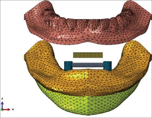
Jaw and overdenture computerized meshed modeling
Figure 2.
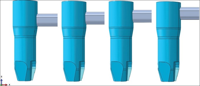
Modeling of four different bar heights (first lever arm)
Figure 4.
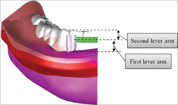
Two lever arms in overdenture assessed in this study
Figure 5.
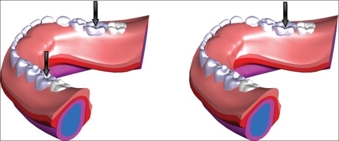
Unilateral and bilateral loads applied to the overdenture
Figure 6.
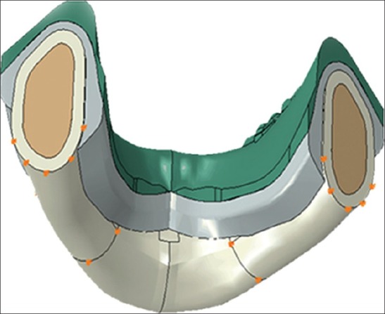
Boundary condition of the model
Table 1.
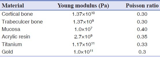
Table 2.
The number of elements and nodes in models
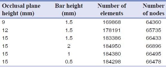
Figure 3.

Modeling of three different occlusal plane heights (second lever arm)
RESULTS
Maximum stress values in bone in unilateral and bilateral load application models are summarized in Tables 3 and 4. In unilateral loading models, the maximum stress was found in a model with 9 mm occlusal plane height and 1.5 mm bar height (6.254 MPa), but in bilateral loading cases the maximum stress was found in a model with 15 mm occlusal plane height and 0.5 mm bar height (3.482 MPa). Maximum stress values in bone were observed mostly in mesial bone adjacent to the ipsilateral implant when unilateral load was applied [Figure 7] and more distal to bone adjacent to the implants when bilateral load was applied [Figure 8].
Table 3.
Stress values generated in the bone with different occlusal plan heights and bar heights by unilateral loading
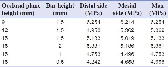
Table 4.
Stress values generated in the bone with different occlusal plan heights and bar heights by bilateral loading
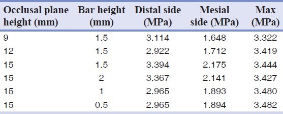
Figure 7.
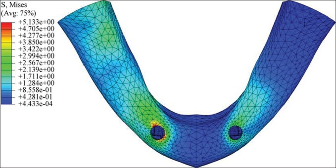
Stress distribution pattern when unilateral load was applied
Figure 8.
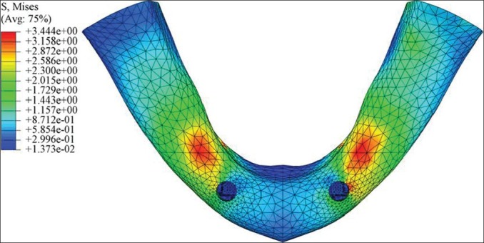
Stress distribution pattern when bilateral load was applied
DISCUSSION
Stress transferred to the implants or periimplant bone under occlusal force applied to the overdentures has been well documented.[4,27–34] Increasing the crown height and degree of nonaxial (eccentric) load over an implant-supported prosthesis increases the risk of excessive occlusal overload because of an increased moment arm.[35] An alternative term is crown height space (CHS), defined as the distance measured from the crest of the alveolar bone to the plane of occlusion. The biomechanics of CHS is related to the mechanics of lever arm.[36] Non-axial loading creates a significant lateral moment, which proportionally increases with the increase of CHS, resulting in stress concentration at the bone surrounding the implant neck[37] and will result more crestal bone loss which is a major criterion for implant success.[38] In the case of removable prostheses, with implant and soft tissue support, CHS is divided into two levers of height : height of attachment system and the distance from the attachment to the occlusal plane.[13] Occlusal load transferred down the long axis of the implant are not considerably affected by CHS.[36] Occlusal loading, however, is very rarely truly axial especially in the case of removable prosthesis.
In this study, when a unilateral load was applied, maximum stress was found on the crestal bone around the implants on the ipsilateral side [Figure 7]. This finding was in agreement with previous studies using unilateral loading,[14,39–41] but in bilateral cases, maximum stress sites were more distal to the crest of the bone surrounding the implants [Figure 8]. This may be because of more evenly distributed loading and different stress patterns and different induced lever arms in these models. To the author's knowledge, no similar FEA has been reported for overdentures under bilateral loading.
With the same vertical restorative space, by increasing bar height, the maximum stress values around implants were increased in unilateral loading models but slightly decreased in bilateral loading cases [Figure 9]. This finding was in agreement with Rismanchian et al. study.[14] No similar study of bilateral loading could be found in the literature. Unilateral and bilateral loading produced completely different stress patterns. This may be because of different induced lever arms in two models. In bilateral loading models, stresses were distributed more evenly. Also, in unilateral loading models, for each 1 mm increase of bar height, the stress increased by around 9%, but stress values in bilateral loading models, decreased by less than 1% for each 1 mm, which is negligible and it might be due to modeling errors.
Figure 9.
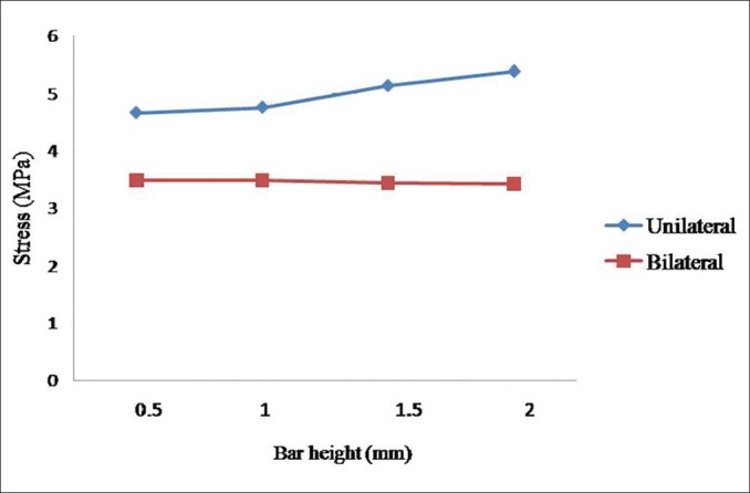
Stress values generated in the bone with different bar heights
For the same bar height, more stresses were predicted by reducing second lever arm (distance from attachment to occlusal plane) when unilateral load was applied [Figure 10]. This may be related to decrease of acrylic resin volume and hardness of denture. By increasing the volume of acrylic resin, stresses may distribute more evenly on denture surfaces and then, less stress values are transferred to implants. Again, a completely different pattern was seen in bilateral loading models where the maximum stress values were increased by increasing the second lever arm. According to FEA simulations, the stresses in these models were more evenly distributed on the bone and less stress concentration was observed on the crestal bone. In unilateral loading models, the increase in acrylic resin volume produced more even stress pattern. This finding is in contradiction with traditional believe in literature and lever arm biomechanics. Again each 1 mm increase of the second lever arm produced more obvious decrease of stress values in unilateral loading models (~3.6%) than the increase in bilateral loading models (~0.6%). With the increase of occlusal plane height, stress values do not change linearly as is seen in Figure 10. With the decrease of acrylic resin thickness, stress values increase sharply. This is due to the increase of overdenture flexibility. This loss of rigidity causes larger overdenture deflections or displacements, less contact areas between overdenture and tissue as well as more stress concentration between bar and clip. These findings are in agreement with previous observations and belief that increasing vertical restorative space will help attachment systems work better as is reported by Ahuja and Cagna.[12] In bilateral loading models, less deflection happened. So the rigidity of aclylic denture may play a small role in stress pattern, and this may be the reason that an increase in acryic resin volume did not decrease the stress value in bilateral loading models.
Figure 10.
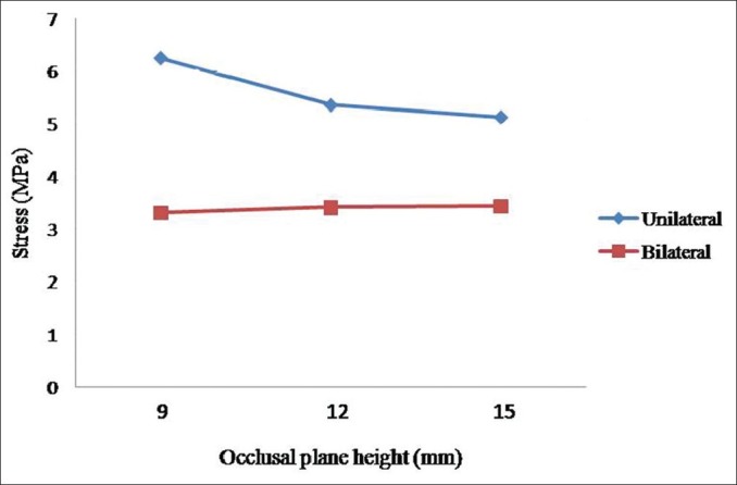
Stress values generated in the bone with different occlusal plane heights
This study showed that when CHS is increased, stress distribution pattern in implant-retained overdentures is truly different from implant-supported fixed prosthesis. This may be related to the resilient retention mechanism in overdentures. In cases of fixed prosthesis, for each 1 mm increase of CHS, the cervical load will increase by 20%.[36] This is more serious and critical than the result of our removable prosthesis study in which for each 1 mm increase of CHS, the cervical load will increase by a maximum of 3.6% for unilateral loading.
It was often claimed that resilient retention mechanisms of overdenture stabilization should be used to distribute stresses between overdenture, tissue, and implant support.[27,31,32,42,43] A vertical gap between bar and clip delayed the axial contact between these parts. Therefore, the implant supported only a weak part of the contact force.[44] The denture bearing area is mainly determined by the number of degrees of freedom of the attachment. Rigid retention mechanism can generate higher stress values on the periimplant bone during mastication as is confirmed in the literature.[26,29,31,32,43] It is accepted that periimplant bone resorption occurs if implant is overloaded. However, the level of stress correlated to bone resorption is not clearly defined in literature. Also, because FEA have theoretical nature and cannot make strict and sharp clinical conclusions,[22,45] the aim of this study was not to report absolute values of stresses but to compare stress values between different models.
Since, the stress variations in bilateral loading models were not significant, and increasing bar height contributed to an increase in stress values in unilateral loading models, so the minimum clinically acceptable bar height is suggested to reduce the stress transferred to implant. In patients treated with bar-supported overdenture, the bar should be more than 2 mm away from the soft tissue to provide an easy access for hygiene.
There are some limitations in FEA studies, mainly in biologic simulations, that oblige studies to assume some simplifications. Bone is a complex living structure without a defined pattern; its characteristics vary among individuals and its actual mechanical properties are not precisely established. Furthermore, the use of FEA in a study of an extremely accurate anatomy of a bone structure may limit the results to that particular structure. The implants were modeled without threads, as the aim of the study was to analyze the stresses on implants and not the mechanical interactions within the bone.[22] It has been said that this assumption results in an underestimation of stress patterns in bone, as reported in previous studies.[46,47] In addition, the connecting screws at the implant–abutment interface were not modeled although some authors showed that modeling the screw is not necessary.[22] It was assumed that the models were homogenous and isotropic. Because this study was comparative in nature, such assumptions would not interfere in the aims, as they were present in all models.[48]
CONCLUSION
Based on the findings of this study, the reduction of bar height and an increase in the thickness of acrylic resin base in implant-supported overdentures are biomechanically favorable and may result in less stress in periimplant bone.
Footnotes
Source of Support: Nil
Conflict of Interest: No
REFERENCES
- 1.Naert I, Alsaadi G, Quirynen M. Prosthetic aspects and patient satisfaction with two-implant-retained mandibular overdentures: A 10-year randomized clinical study. Int J Prosthodont. 2004;17:401–10. [PubMed] [Google Scholar]
- 2.Naert I, Alsaadi G, van Steenberghe D, Quirynen M. A 10-year randomized clinical trial on the influence of splinted and unsplinted oral implants retaining mandibular overdentures: Peri-implant outcome. Int J Oral Maxillofac Implants. 2004;19:695–702. [PubMed] [Google Scholar]
- 3.Fanuscu MI, Caputo AA. Influence of attachment systems on load transfer of an implant-assisted maxillary overdenture. J Prosthodont. 2004;13:214–20. doi: 10.1111/j.1532-849X.2004.04041.x. [DOI] [PubMed] [Google Scholar]
- 4.Tokuhisa M, Matsushita Y, Koyano K. In vitro study of a mandibular implant overdenture retained with ball, magnet, or bar attachments: Comparison of load transfer and denture stability. Int J Prosthodont. 2003;16:128–34. [PubMed] [Google Scholar]
- 5.MacEntee MI, Walton JN, Glick N. A clinical trial of patient satisfaction and prosthodontic needs with ball and bar attachments for implant-retained complete overdentures: Three-year results. J Prosthet Dent. 2005;93:28–37. doi: 10.1016/j.prosdent.2004.10.013. [DOI] [PubMed] [Google Scholar]
- 6.Meijer HJ, Kuiper JH, Starmans FJ, Bosman F. Stress distribution around dental implants: Influence of superstructure, length of implants, and height of mandible. J Prosthet Dent. 1992;68:96–102. doi: 10.1016/0022-3913(92)90293-j. [DOI] [PubMed] [Google Scholar]
- 7.AbuJamra NF, Stavridakis MM, Miller RB. Evaluation of interarch space for implant restorations in edentulous patients: A laboratory technique. J Prosthodont. 2000;9:102–5. doi: 10.1111/j.1532-849x.2000.00102.x. [DOI] [PubMed] [Google Scholar]
- 8.Cagna DR, Massad JJ, Schiesser FJ. The neutral zone revisited: From historical concepts to modern application. J Prosthet Dent. 2009;101:405–12. doi: 10.1016/S0022-3913(09)60087-1. [DOI] [PubMed] [Google Scholar]
- 9.Atwood DA. Reduction of residual ridges: A major oral disease entity. J Prosthet Dent. 1971;26:266–79. doi: 10.1016/0022-3913(71)90069-2. [DOI] [PubMed] [Google Scholar]
- 10.Tallgren A. The continuing reduction of the residual alveolar ridges in complete denture wearers : A mixed-longitudinal study covering 25 years. J Prosthet Dent. 1972;27:120–32. doi: 10.1016/0022-3913(72)90188-6. [DOI] [PubMed] [Google Scholar]
- 11.Ahuja S, Cagna DR. Defining available restorative space for implant overdentures. J Prosthet Dent. 2010;104:133–6. doi: 10.1016/S0022-3913(10)60107-2. [DOI] [PubMed] [Google Scholar]
- 12.Ahuja S, Cagna DR. Classification and management of restorative space in edentulous implant overdenture patients. J Prosthet Dent. 2011;105:332–7. doi: 10.1016/S0022-3913(11)60064-4. [DOI] [PubMed] [Google Scholar]
- 13.Misch CE, Goodacre CJ, Finley JM, Misch CM, Marinbach M, Dabrowsky T, et al. Consensus conference panel report: Crown-height space guidelines for implant dentistry-part 2. Implant Dent. 2006;15:113–21. doi: 10.1097/01.id.0000217907.18396.18. [DOI] [PubMed] [Google Scholar]
- 14.Rismanchian M, Dakhilalian M, Bajoghli F, Ghasemi E, Sadr-Eshkevari P. Implant-retained mandibular bar-supported overlay dentures: A finite element stress analysis of four different bar heights. J Oral Implantol. 2012;38:133–9. doi: 10.1563/AAID-JOI-D-09-00037.1. [DOI] [PubMed] [Google Scholar]
- 15.Misch CE. The edentulous mandible: An organized approach to implant-supported overdentures. 3rd ed. Saunders: Mosby; 2008. pp. 293–313. [Google Scholar]
- 16.Nickel JC, McLachlan KR. In vitro measurement of the frictional properties of the temporomandibular joint disc. Arch Oral Biol. 1994;39:323–31. doi: 10.1016/0003-9969(94)90124-4. [DOI] [PubMed] [Google Scholar]
- 17.O’Mahony AM, Williams JL, Spencer P. Anisotropic elasticity of cortical and cancellous bone in the posterior mandible increases peri-implant stress and strain under oblique loading. Clin Oral Implants Res. 2001;12:648–57. doi: 10.1034/j.1600-0501.2001.120614.x. [DOI] [PubMed] [Google Scholar]
- 18.Dubois G, Daas M, Bonnet AS, Lipinski P. Biomechanical study of a prosthetic solution based on an angled abutment: Case of upper lateral incisor. Med Eng Phys. 2007;29:989–98. doi: 10.1016/j.medengphy.2006.10.017. [DOI] [PubMed] [Google Scholar]
- 19.Ortorp A, Jemt T. Clinical experiences of CNC-milled titanium frameworks supported by implants in the edentulous jaw: 1-year prospective study. Clin Implant Dent Relat Res. 2000;2:2–9. doi: 10.1111/j.1708-8208.2000.tb00101.x. [DOI] [PubMed] [Google Scholar]
- 20.van Zyl PP, Grundling NL, Jooste CH, Terblanche E. Three-dimensional finite element model of a human mandible incorporating six osseointegrated implants for stress analysis of mandibular cantilever prostheses. Int J Oral Maxillofac Implants. 1995;10:51–7. [PubMed] [Google Scholar]
- 21.Bonnet AS, Postaire M, Lipinski P. Biomechanical study of mandible bone supporting a four-implant retained bridge: Finite element analysis of the influence of bone anisotropy and foodstuff position. Med Eng Phys. 2009;31:806–15. doi: 10.1016/j.medengphy.2009.03.004. [DOI] [PubMed] [Google Scholar]
- 22.Zampelis A, Rangert B, Heijl L. Tilting of splinted implants for improved prosthodontic support: A two-dimensional finite element analysis. J Prosthet Dent. 2007;97:S35–43. doi: 10.1016/S0022-3913(07)60006-7. [DOI] [PubMed] [Google Scholar]
- 23.Greco GD, Jansen WC, Landre Junior J, Seraidarian PI. Stress analysis on the free-end distal extension of an implant-supported mandibular complete denture. Braz Oral Res. 2009;23:182–9. doi: 10.1590/s1806-83242009000200014. [DOI] [PubMed] [Google Scholar]
- 24.Menicucci G, Mossolov A, Mozzati M, Lorenzetti M, Preti G. Tooth-implant connection: Some biomechanical aspects based on finite element analyses. Clin Oral Implants Res. 2002;13:334–41. doi: 10.1034/j.1600-0501.2002.130315.x. [DOI] [PubMed] [Google Scholar]
- 25.Maeda Y, Wood WW. Finite element method simulation of bone resorption beneath a complete denture. J Dent Res. 1989;68:1370–3. doi: 10.1177/00220345890680091601. [DOI] [PubMed] [Google Scholar]
- 26.Chun HJ, Park DN, Han CH, Heo SJ, Heo MS, Koak JY. Stress distributions in maxillary bone surrounding overdenture implants with different overdenture attachments. J Oral Rehabil. 2005;32:193–205. doi: 10.1111/j.1365-2842.2004.01407.x. [DOI] [PubMed] [Google Scholar]
- 27.Mericske-Stern R, Piotti M, Sirtes G. 3-D in vivo force measurements on mandibular implants supporting overdentures. A comparative study. Clin Oral Implants Res. 1996;7:387–96. doi: 10.1034/j.1600-0501.1996.070413.x. [DOI] [PubMed] [Google Scholar]
- 28.Duyck J, Van Oosterwyck H, vander Sloten J, De Cooman M, Puers R, Naert I. In vivo forces on oral implants supporting a mandibular overdenture: The influence of attachment system. Clin Oral Investig. 1999;3:201–7. doi: 10.1007/s007840050102. [DOI] [PubMed] [Google Scholar]
- 29.Menicucci G, Lorenzetti M, Pera P, Preti G. Mandibular implant-retained overdenture: A clinical trial of two anchorage systems. Int J Oral Maxillofac Implants. 1998;13:851–6. [PubMed] [Google Scholar]
- 30.Kenney R, Richards MW. Photoelastic stress patterns produced by implant-retained overdentures. J Prosthet Dent. 1998;80:559–64. doi: 10.1016/s0022-3913(98)70032-0. [DOI] [PubMed] [Google Scholar]
- 31.Porter JA, Jr, Petropoulos VC, Brunski JB. Comparison of load distribution for implant overdenture attachments. Int J Oral Maxillofac Implants. 2002;17:651–62. [PubMed] [Google Scholar]
- 32.Menicucci G, Lorenzetti M, Pera P, Preti G. Mandibular implant-retained overdenture: Finite element analysis of two anchorage systems. Int J Oral Maxillofac Implants. 1998;13:369–76. [PubMed] [Google Scholar]
- 33.Cekic C, Akca K, Cehreli MC. Effects of attachment design on strains around implants supporting overdentures. Quintessence Int. 2007;38:e291–7. [PubMed] [Google Scholar]
- 34.Meijer HJ, Starmans FJ, Steen WH, Bosman F. A three-dimensional, finite-element analysis of bone around dental implants in an edentulous human mandible. Arch Oral Biol. 1993;38:491–6. doi: 10.1016/0003-9969(93)90185-o. [DOI] [PubMed] [Google Scholar]
- 35.Richter EJ. In vivo horizontal bending moments on implants. Int J Oral Maxillofac Implants. 1998;13:232–44. [PubMed] [Google Scholar]
- 36.Sarment DP, Misch CE. Diagnostic Casts and Surgical templates. In: Misch CE, editor. Contemporary implant dentistry. 3rd ed. Mosby: Sunders; 2008. pp. 276–92. [Google Scholar]
- 37.Barbier L, Schepers E. Adaptive bone remodeling around oral implants under axial and nonaxial loading conditions in the dog mandible. Int J Oral Maxillofac Implants. 1997;12:215–23. [PubMed] [Google Scholar]
- 38.Salimi H, Savabi O, Nejatidanesh F. Currentresults and trends in platform switching. Dent Res J (Isfahan) 2011;8:S30–6. [PMC free article] [PubMed] [Google Scholar]
- 39.Skalak R. Biomechanical considerations in osseointegrated prostheses. J Prosthet Dent. 1983;49:843–8. doi: 10.1016/0022-3913(83)90361-x. [DOI] [PubMed] [Google Scholar]
- 40.Quirynen M, Naert I, van Steenberghe D. Fixture design and overload influence marginal bone loss and fixture success in the Branemark system. Clin Oral Implants Res. 1992;3:104–11. doi: 10.1034/j.1600-0501.1992.030302.x. [DOI] [PubMed] [Google Scholar]
- 41.Holmes DC, Loftus JT. Influence of bone quality on stress distribution for endosseous implants. J Oral Implantol. 1997;23:104–11. [PubMed] [Google Scholar]
- 42.Walton JN, MacEntee MI. Problems with prostheses on implants: A retrospective study. J Prosthet Dent. 1994;71:283–8. doi: 10.1016/0022-3913(94)90468-5. [DOI] [PubMed] [Google Scholar]
- 43.Heckmann SM, Winter W, Meyer M, Weber HP, Wichmann MG. Overdenture attachment selection and the loading of implant and denture-bearing area. Part 2: A methodical study using five types of attachment. Clin Oral Implants Res. 2001;12:640–7. doi: 10.1034/j.1600-0501.2001.120613.x. [DOI] [PubMed] [Google Scholar]
- 44.Daas M, Dubois G, Bonnet AS, Lipinski P, Rignon-Bret C. A complete finite element model of a mandibular implant-retained overdenture with two implants: Comparison between rigid and resilient attachment configurations. Med Eng Phys. 2008;30:218–25. doi: 10.1016/j.medengphy.2007.02.005. [DOI] [PubMed] [Google Scholar]
- 45.Satoh T, Maeda Y, Komiyama Y. Biomechanical rationale for intentionally inclinedimplants in the posterior mandible using 3D finite element analysis. Int J Oral Maxillofac Implants. 2005;20:533–9. [PubMed] [Google Scholar]
- 46.Natali AN, Pavan PG, Ruggero AL. Evaluation of stress induced in peri-implant bone tissue by misfit in multi-implant prosthesis. Dent Mater. 2006;22:388–95. doi: 10.1016/j.dental.2005.08.001. [DOI] [PubMed] [Google Scholar]
- 47.Bellini CM, Romeo D, Galbusera F, Taschieri S, Raimondi MT, Zampelis A, et al. Comparison of tilted versus nontilted implant-supported prosthetic designs for the restoration of the edentuous mandible: A biomechanical study. Int J Oral Maxillofac Implants. 2009;24:511–7. [PubMed] [Google Scholar]
- 48.Silva GC, Mendonça JA, Lopes LR, Landre J., Jr Stress patterns on implants in prostheses supported by four or six implants: A three-dimensional finite element analysis. Int J Oral Maxillofac Implants. 2010;25:239–46. [PubMed] [Google Scholar]


