Abstract
The ability for individuals with spinal cord injury (SCI) to affect changes in standing posture with functional neuromuscular stimulation (FNS) was explored using an anatomically inspired musculoskeletal model of the trunk, pelvis and lower extremities (LE). The model tracked trajectories for anteriorly and laterally shifting movements away from erect stance. Forces were applied to both shoulders to represent upper extremity (UE) interaction with an assistive device (e.g., a walker). The muscle excitations required to execute shifting maneuvers with UE forces <10% body-weight (BW) were determined via dynamic optimization. Nine muscle sets were examined to maximize control of shifting posture. Inclusion of the Psoas and External Obliques bilaterally resulted in the least relative UE effort (0.119, mean UE effort = 45.3N ≡ 5.4% BW) for anterior shifting. For lateral shifting, the set including the Psoas and Latissimus Dorsi bilaterally yielded the best performance (0.025, mean UE effort = 27.8 N ≡ 3.3% BW). However, adding the Psoas alone bilaterally competed favorably in overall best performance across both maneuvers. This study suggests suitable activation to specific muscles of the trunk and LE can enable individuals with SCI to alter their standing postures with minimal upper-body effort and subsequently increase reach and standing work volume.
Keywords: Human Standing, Functional Neuromuscular Stimulation (FNS), Standing Balance, Reaching, Posture Shifting, Spinal Cord Injury
INTRODUCTION
Quiet standing and simple stepping maneuvers can be restored to individuals paralyzed by spinal cord injury (SCI) through neuroprostheses employing functional neuromuscular stimulation (FNS). Existing FNS systems maintain a single erect standing posture by continuously activating the knee, hip and trunk extensors (Jaeger et al, 1989; Yarcony et al., 1990; Triolo et al, 1996). Current systems essentially lock users into a single upright posture with no means to alter position except by pulling or pushing against the continuously activated muscles with the upper extremities (Kobetic et al, 1999). Furthermore, existing FNS systems are capable of activating only a small number of carefully selected muscles, making advanced functions and finer movements difficult. The purpose of this study was to examine the feasibility of dynamically shifting standing posture with low upper extremity exertion and a minimal number of optimally selected muscles. The ability to dynamically shift posture by appropriately modulating stimulation would expand work volume to allow users to reach and manipulate objects or prepare for anticipated disturbances, thus affording greater control over the environment and reducing the potential for falls.
Simplifying assumptions in prior modeling studies examining standing balance include: actuating the system by joint moments (Hemami and Wyman, 1979, Kim et al., 2006, Matjacic et al., 2001), representing the body as a multi-joint single inverted pendulum (Soetanto et al, 2001, Gollee et al., 2004), or combining pelvis and trunk into a single segment (Mihelj and Munih, 2004). While adequate for theoretical investigations into disturbance response and single limb stance, these models were essentially static oversimplifications. Exploring FNS-generated movement in three dimensions is important because muscle actions are not confined to single planes. For instance, stimulating the tibialis anterior after SCI causes the body to both fall forward (a sagittal plane movement) and lean sideways (a coronal plane movement). Moreover, the closed chain defined by maintaining the feet on the ground effectively reduces the system degrees of freedom but couples their individual effects across all movement planes. Thus, stimulation of any muscle about the closed chain can result in complex motor behavior unaccounted for by planar models. Finally, it is necessary to represent the pelvis and trunk separately since important muscles attach to one without spanning the other. A single pelvis-trunk segment could require complex synergy patterns from many muscles to constrain the anatomy to fit the simplified model.
Recent simulation studies with 3D musculoskeletal models have demonstrated the possibility of holding the body statically at discrete bipedal postures with FNS (Heilman, et al., 2006; Gartman, et al., 2008). These studies used static optimization to determine optimal muscle sets to maintain the body in different postures. However, the muscle forces calculated to keep the body in static equilibrium are not guaranteed to be sufficient to move the body dynamically from one posture to another.
In our study, a 3D model was used to explore the feasibility of producing dynamic movements with FNS in a typical individual with paralysis. The results will inform future clinical implementation of neuroprostheses designed to restore standing balance after SCI and assist surgeons and rehabilitationists in the selection of optimal muscles and stimulation patterns.
METHODS
Musculoskeletal Model
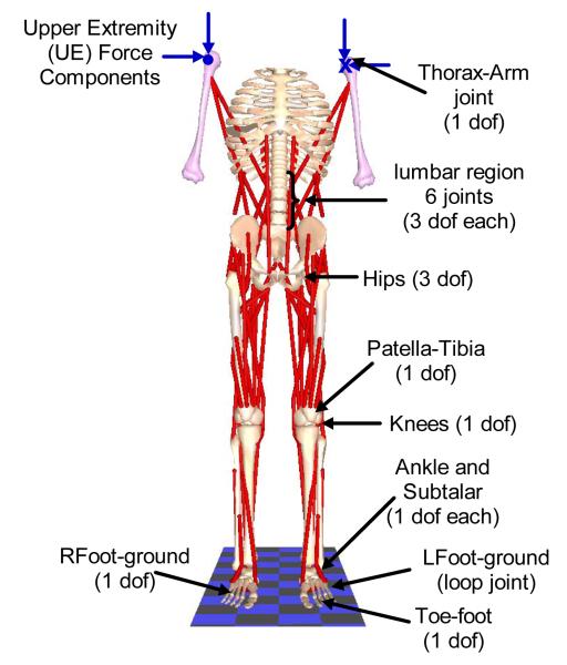
The musculoskeletal model (Figure 1) was a doubly-supported inverted pendulum consisting of 21 bone segments connected by 21 joints (Zhao, et al. 1998). The segmental mass and inertia properties were calculated according to anthropometric tables (Winter, 1990) based on an average healthy male (weight 840.7 N, height 1.72 m). The model was actuated by 32 Hill-type muscle elements (Zajac, 1989) including bilateral Medial Gastrocnemius (MEDGAS), Tibialis Anterior (TIBANT), Vastus Lateralis and Medialis (VASTI), Semimembranosus (SEMIMEM), Adductor Magnus (AMAG), Gluteus Medius (GMED), Gluteus Maximus (GMAX), Psoas (PSOAS), Erector Spinae (ESPINAE), External Obliques (EXTOBL), Latissimus Dorsi (LDORSI), and Sartorius (SART). For clarity, muscles on the left side were identified with a prefix (i.e., LMEDGAS). Broad hip muscles (GMAX, GMED, and AMAG) were each modeled as two separate elements, but treated as single muscles by requiring them to have the same excitation.
FIGURE 1.
Human bipedal musculoskeletal model used in the study showing the joints. Single degree-of-freedom revolute joints connected each foot to the talus to define the subtalar joints; the talus to the tibia/fibula to define the ankle joints, and the tibia/fibula to the femur to define the knee joints. Three degrees-of-freedom gimbal joints connected the two femurs to the pelvis to define flexion/extension, adduction/abduction and internal/external rotation of the hip joints. The torso attaches to the pelvis via a three degree-of-freedom gimbal joint that defined trunk flexion/extension (pitch), lateral bending (roll) and axial rotation (yaw). Five other lumbar joints also had three degrees-of-freedom each but moved synergistically in accordance with anatomically realistic kinematic constraints with respect to the torso-pelvic joint (White and Panjabi, 1990; Wilkenfeld et al., 2006). All other joints are prescribed to have zero velocity and acceleration; but were invaluable in defining realistic muscle wrapping points.
Characteristics of the muscles were modified to match known changes that occur as a consequence of paralysis. Maximum moments generated with FNS following SCI are approximately 50% of able-bodied values (Heilman et al, 2006). To include this effect, the maximum isometric forces of all muscles in the model were reduced by half. Properties of the passive structures across the joints were experimentally determined from individuals with SCI (Amankwah et al., 2004; Lambrecht et al., 2009). To further capture the effects of SCI, the effort exerted by the upper extremities (UE) on a support device was included in the formulation of the mechanical system (Nataraj et al, 2010). UE effort was defined in terms of all six components (, , , , , ) of the resultant forces (FL and FR) exerted at the left and right shoulders by voluntarily interacting with a walker.
Muscle Selection
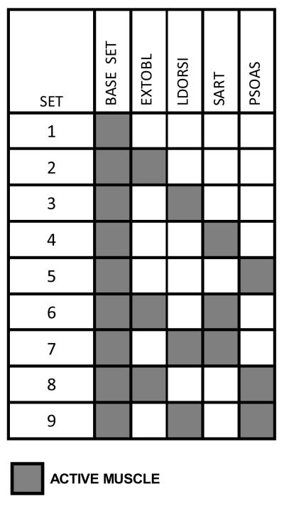
Nine muscle sets (Table 1) built around a base group of 8 bilateral muscles (MEDGAS, TIBANT, VASTI, SEMIMEM, AMAG, GMED, GMAX and ESPINAE) were specified for the dynamic optimization. Muscles were added to the base set for specific functions: External Obliques for enhanced trunk flexion and lateral bending; Latissimus Dorsi for additional trunk extension; Sartorius for hip flexion; and Psoas for hip and trunk flexion.
TABLE 1.
Muscle sets used in the optimization study. Each set consisted of the base set plus zero or more additional muscles chosen to enhance the capabilities of the base set.
|
Dynamic Optimization
Dynamic optimization can determine optimal muscle excitations and UE effort required to move the body from one position to another because the unknown control variables (muscle excitations and UE forces) are functions of time. This can be done by minimizing a scalar objective function subject to differential and non-differential (algebraic) constraints in the unknown variables.
(a) Objective function
The scalar objective function for the optimization was defined to penalize excessive deviation from the desired trajectories throughout the path and any other function defined at the final time:
| (1) |
Terminal cost is to be evaluated at the final time tf. The first term in the integrand represents the penalty for trajectory deviation. is the set of n joint angles at time t, is the corresponding desired or specified quantities at time t; the control is the vector of (m-6) muscle excitations and 6 UE force components at time t, ). Q(nxn) is a weighting matrix, is a vector of unknown constant parameters.
(b) Comparing muscle sets – terminal cost function
To determine the muscle set that resulted in the least UE effort, we defined a metric called relative UE effort (RUEE) representing the ratio between the work done by the UEs and the stimulated muscles. The total (absolute) musculotendon work was computed as the integral of the joint power generated by the muscle fibers (Kautz et al., 1994; Neptune, et al., 2009):
| (2) |
where and were the force and velocity of the ith musculotendon respectively, and M was the total number of muscles in that set.
The work done by the UE was computed as the integral of the (absolute) product of the UE force and the velocity of the trunk at the arms:
| (3) |
where is the linear velocity of the arms at the shoulders. The relative UE effort was defined as:
| (4) |
To include the RUEE in the objective function J (equation 1), the integrands in (2) and (3) were used to define the right hand sides of two auxiliary differential equations:
| (5) |
| (6) |
It can be proved that the value of each of the two variables x(tf)MT and x(tf)UE at the final time tf defined the respective terms WMT and WUE (Kaya, et al., 2004). The ratio RUEE = x(tf)UE/x(tf)MT defined the terminal cost [g(x,u,π)]tf in equation (1).
A normalization process (Audu and Davy, 1985) was employed to accommodate the final time tf which was an unknown parameter in this formulation. Starting from the inequality t0 ≤ t ≤ tf, subtracting t0 from all sides and dividing by tf – t0 gives:
| (7) |
Defining a new variable , (7) becomes 0 ≤ τ ≤ 1. Solving for t gives t = τ(tf–t0)+t0. For most practical purposes, t0 =0 ; hence t = τtf. Replacing all occurrences of t with the expression τtf in (1) and all the constraint equations effectively achieved a change in variables from t to τ. Since dt = tfdτ = π1dτ equation (1) becomes:
| (8) |
tf = π1 was the only unknown component of the parameter vector π which was part of the optimization decision variables.
(c) Differential Constraints
Differential constraints represented the equations of motion for the skeletal sub-system (Newton-Euler Equations), Hill’s muscle dynamic equations (Zajac, 1989) and the two auxiliary equations (5) and (6). By the transformation dt = tfdτ = π1dτ the equations become:
| (9) |
Newton-Euler equations were derived with SD/FAST (Parametric Technology Corp., Needham, MA) and AUTOLEV (Online Dynamics Inc, Sunnyvale, CA) and muscle dynamics were as defined in SIMM/Dynamics Pipeline (MusculoGraphics, Inc., Santa Rosa, CA).
(d) Non-differential constraints
Four sets of non-differential constraints were applied. The first represented loop closure equations for bipedal stance. These equations are highly complex functions of the joint angles internally generated by SD/FAST/AUTOLEV and take the general form:
| (10) |
The second represented the vector of bounds placed on muscle excitations and UE force components:
| (11) |
| (12) |
The third represented the vector of constraints imposing the synergistic movement of the lumbar joints (Wilkenfeld, et al., 2006):
| (13) |
where αT is the overall angle between the torso and the pelvis, αS1–L5 is the angle between the first sacral (S1) and the fifth lumbar (L5) vertebrae, etc. The fourth constrained UE forces so that the combined resultant at both shoulders did not exceed 10% of body weight, i.e.
| (14) |
For computational efficiency, UE forces were normalized to lie between −1 and 1 (equation 12). Bounds on the UE force components were defined as:
| (15) |
where i = [x, y or z]. Assuming the arm was forward 30° while holding an instrumented handle, the maximum effort exerted upward is approximately the same as the maximum effort exerted downward. The same applied to the anterior-posterior (AP) and the medio-lateral (ML) directions. Maximum efforts in the AP, ML and up/down directions were in the ratios 1.08 : 0.82 : 1 (Chaffin et al, 2006). Assuming minimum and maximum efforts on opposite arms are equal (), the components could be divided by the absolute value of the maximum effort to yield the normalized control variable :
| (16) |
To ensure that when the resultant of all 6 components was always less than 10%BW, the maximum for all force components was chosen as maxFL/R = (0.0288675)*BW. At every iteration the actual UE force applied on the system was defined as:
| (17) |
which always satisfies equation (14) for all values .
The dynamic optimization problem defined by equations (3) to (14) was solved with the software PSOPT (Pseudospectral Optimal Control Solver in C++), which utilizes direct collocation to convert it to a static optimization problem (Becerra, 2010). The resulting static optimization was solved with IPOPT (Wachter and Biegler, 2006). PSOPT internally discretizes all time varying functions starting from a coarse mesh of the independent variable τ∈[0,1]. Thereafter, the various time functions were approximated as weighted sums of smooth Legendre or Chebyshev polynomial basis functions.
Posture Shifts
To assess the potential for individuals with SCI to execute shifting maneuvers with FNS, the following alterations in standing postures were examined:
a) Forward Lean
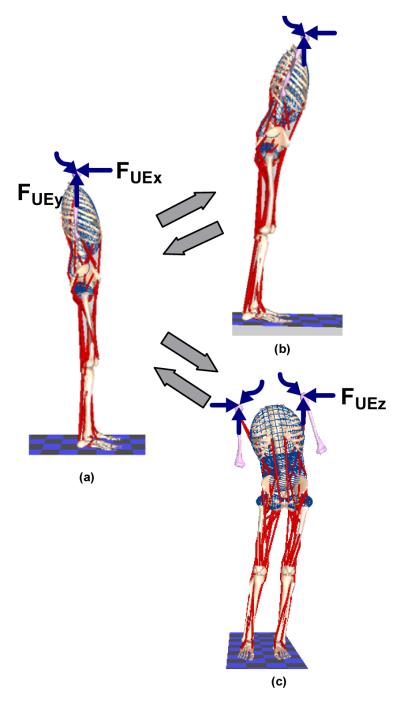
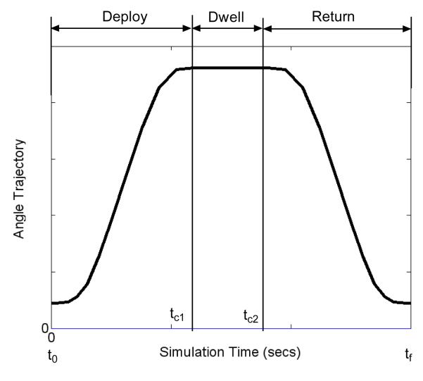
Forward leaning postures were achieved by changing ankle dorsiflexion, hip flexion and trunk pitch angles from zero (Figure 2a), to 5°, 10° and 5° respectively while maintaining all other angles near zero (Figure 2b). The model started at the erect posture with zero velocity and arrived at the destination with zero velocity followed by a short dwell period before returning to the erect position in the reverse direction. This typical trajectory is shown in Figure 3. Tracking accuracy was measured as the root-mean-square error (RMSE) between the specified and the computed trajectories.
FIGURE 2.
Posture changes from erect (a). The upper right hand side figure (b) shows a forward leaning posture from the erect posture and return; and the lower right hand side figure (c) shows a side shift posture from the erect posture and return. The straight colored arrows represent forces acting in the plane of the paper while the wavy lines represent forces acting perpendicular to the plane of the paper.
FIGURE 3.
A typical joint angle trajectory to be tracked by the dynamic optimization algorithm. The first part of the trajectory from time t0 to time tc1 is the deploy phase when the body moves away from the erect posture; the second part from time tc1 to time tc2 is the dwell phase when the body remains in the shifted position while the third phase from time tc2 to final time tf is the return phase when the body returns to the erect posture. By the design of the trajectory, the joint angle velocities will be zero at the beginning and end of every phase. The shapes of the deploy and return portions of the trajectories were deduced from experimental data with able-bodied individuals doing a number of leaning maneuvers.
b)Side Shift
Side shifting was accomplished by moving the pelvis to the left about the hips and ankles as depicted in Figure 2(b). The final position was defined by major changes in hip adduction, subtalar and trunk roll angles. During the deployment phase the right/left hips were abducted/adducted from 0° to 8° while the right/left subtalar angles were inverted/everted from 0° to 10° and the trunk tilted from 0° to 10° toward the right. In the return phase all angles were restored to zero. A minor amount of knee flexion (typically less than 6°) was required to preserve the closed-chain during side shifting.
Optimal simulation time
In a preliminary analysis using the base muscle set, the optimization problems were solved for the optimal time to a) move the body from an initial erect posture to the desired forward leaning position and return to erect, and b) move the body from an initial erect posture to the desired side shifted position and return to erect posture with no dwell periods.
RESULTS
1. Optimal simulation times
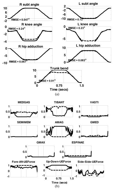
Optimal times for the combined deploy and return phases of the forward lean and side shifts without dwell were 1274 ms and 1155 ms respectively. We chose to use 1200 ms equally divided between deploy and return phases separated by an arbitrary dwell period of 300 ms for all subsequent simulations. Figures 4 and 5 show typical results from the forward and side leaning maneuvers with the base muscle set (Muscle Set 1). Results from other muscle sets were similar and omitted for brevity.
FIGURE 4.
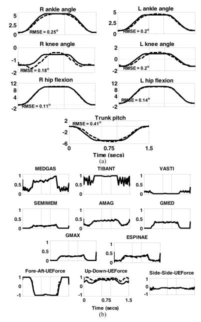
Results of dynamic optimization to move the body from an erect posture to a forward lean position, dwelling for 300 ms and then returning to the erect position. (a) Joint angle trajectories. Solid lines are the desired or specified trajectories while the dashed lines are those obtained by dynamic optimization. Positive directions for the joints are: subtalar (inversion), ankle (dorsiflexion), knee (extension), hip (flexion, adduction, internal rotation), trunk pitch (extension) and trunk bend( to the right); (b) muscles excitations and normalized upper extremity (UE) forces required to execute the desired motion. Solid lines are for the right side while dashed lines are for the left side. The thin vertical lines represent the boundaries of the three phases. The directions for UE force components were: Fore-aft – positive forward; Vertical component – positive upward and Side-to-side component – positive to the right of the body. The numbers inside each of the joint angle sub-plots were the RMSE values.
FIGURE 5.
Results of dynamic optimization to move the body from an erect posture to a side-shift position, dwelling for 300 ms and then returning to the erect position. (a) Joint angle trajectories. Solid lines are the desired or specified trajectories while the dashed lines are those obtained by dynamic optimization. Positive directions for the joints are: subtalar (inversion), ankle (dorsiflexion), knee (extension), hip (flexion, adduction, internal rotation), trunk pitch (extension) and trunk bend( to the right); (b) muscles excitations and normalized upper extremity (UE) forces required to execute the desired motion. Solid lines are for the right side while dashed lines are for the left side. The thin vertical lines represent the boundaries of the three phases. The directions for UE force components were: Fore-aft – positive forward; Vertical component – positive upward and Side-to-side component – positive to the right of the body. The numbers inside each of the joint angle sub-plots were the RMSE values.
2. Forward Lean
Figure 4 shows the lower extremity and trunk joint angles and muscle excitations required to deploy the body from an erect posture to a forward leaning position. The tracking RMSE for all angles were below 1° with the largest occurring in hip rotation (not shown).
Muscle activities and UE forces were nearly symmetric on the left (dashed) and right (solid). TIBANT and MEDGAS were most active muscles during the deploy phase, with the most prominent UE forces in the AP direction to assist moving the body toward the target. The largest muscle activity occurred during the dwell phase when the hip and trunk extensors (SEMIMEM, AMAG, GMED, GMAX and ESPINAE) were required to hold the body in position. During this phase, the fore-aft component of the UE force reversed direction to act posteriorly to help maintain the body in the forward position. In the return phase, the most prominent activity was again at the ankles (TIBANT and MEDGAS). The AP components of the UE forces which initially helped push the body backward reversed direction to decelerate it at the end of the movement. Throughout all phases, the vertical components of the UE forces remained at approximately 2.5% BW to help prevent collapse. Some muscle excitations (TIBANT) exhibited oscillations during the movement phases. This may be a consequence of the spline fit used by the optimization algorithm. Also, the UE forces tended toward saturation at the limit of 10% BW. This is reasonable because SCI subjects typically require UE effort of 12-25%BW to support quiet standing with stimulation (Kobetic et al, 1999), and demonstrates that dynamic movements were generated primarily by the stimulated muscles.
3. Side Shift
Figure 5 depicts joint angles and muscle excitations required to shift the pelvis left and return using the base set (Muscle Set 1). The optimization tracked the desired trajectories with RMSE below 1° in all cases. The main muscles recruited during this maneuver were TIBANT and AMAG. The largest activity occurred in the dwell phase with a marked difference between left and right sides since movement occurred primarily in the coronal plane. Left TIBANT activity increased while right TIBANT activity coincidentally decreased. The opposite occurred at the hip where right-side AMAG activity increased while left-side activity decreased accordingly. GMED was only recruited for support during the dwell phase and only on the left side. The AP and vertical components of the UE forces were most active throughout (~ 2.5%BW). The former maintained posture in the sagittal plane while the latter helped keep the body erect. The apparent instability in the sagittal plane and corresponding UE effort was due to the knee flexion necessary to maintain the closed-chain. During the dwell phase, right side UE effort increased to help maintain the trunk at the desired orientation while left UE effort decreased. ML UE effort remained close to zero throughout the maneuver except during transitions to and from dwell.
4. Relative, Mean and Maximum UE Effort
Table 2 lists the relative, mean and maximum resultant UE efforts for all 9 muscle sets. Muscle sets 5, 8 and 9 (shaded) were most effective in minimizing RUEE for both forward and side shifts. The three sets also resulted in lower mean UE efforts. Muscle set 8 (base plus bilateral PSOAS and EXTOBL) was most effective for forward leaning. Muscle set 9 (base plus bilateral PSOAS and LDORSI ) was best for side shifting, but was closely followed by muscle set 5 (base plus PSOAS bilaterally). Muscle set 5 was also the second best combination for the forward lean maneuver with a mean UE effort slightly lower than Muscle set 8.
TABLE 2.
Relative (RUEE), mean (Fmean) and maximum (Fmax) upper extremity effort (in N) for the nine muscle sets examined. Values of forces in parentheses represent the equivalent quantities expressed as percentage of body weight (BW)
| MUSCLE SET |
FORWARD LEAN | SIDE SHIFT | ||||
|---|---|---|---|---|---|---|
| RUEE | Fmax (N) | Fmean (N) | RUEE | Fmax (N) | Fmean (N) | |
| 1 | 0.266 | 67.90 (8.08) |
57.14 (6.80) |
0.082 | 57.46 (6.83) |
49.23 (5.86) |
| 2 | 0.235 | 72.84 (8.66) |
60.40 (7.18) |
0.125 | 80.12 (9.53) |
57.24 (6.81) |
| 3 | 0.266 | 67.30 (8.01) |
58.00 (6.90) |
0.136 | 67.15 (7.99) |
51.03 (6.07) |
| 4 | 0.214 | 64.23 (7.64) |
52.81 (6.28) |
0.170 | 74.66 (8.88) |
52.34 (6.23) |
| 5 | 0.133 | 62.08 (7.38) |
44.80 (5.33) |
0.031 | 40.73 (4.84) |
30.54 (3.63) |
| 6 | 0.199 | 63.00 (7.49) |
53.68 (6.39) |
0.090 | 68.59 (8.16) |
46.39 (5.52) |
| 7 | 0.225 | 60.23 (7.16) |
52.04 (6.19) |
0.117 | 63.95 (7.61) |
47.30 (5.63) |
| 8 | 0.119 | 62.41 (7.42) |
45.31 (5.39) |
0.025 | 39.09 (4.65) |
28.63 (3.41) |
| 9 | 0.135 | 63.94 (7.61) |
46.11 (5.48) |
0.025 | 35.33 (4.20) |
27.79 (3.31) |
DISCUSSION
This paper explored the theoretic feasibility of enabling individuals with SCI to undertake posture shifts while standing with FNS using a 3D musculoskeletal model adjusted for muscle properties typically observed in individuals with SCI and a powerful dynamic optimization software package. In these in silico experiments, total UE effort was restricted to less than 10%BW. Studies by Kobetic et al (1999) have shown that the upper extremities support an average of 25% BW while standing quietly with continuous open-loop stimulation; indicating that 10% is low and thus very practical. Muscle Sets 5, 8 and 9 clearly outperformed the others in terms of minimizing overall UE effort. Whereas only Psoas would be sufficient for the forward lean maneuver, adding either External Obliques or Latissimus Dorsi would be essential for sideways lean. Psoas was common to all three sets, and should be targeted in development of future FNS standing systems. Latissimus Dorsi may be preferable to External Obliques because of its excitability and ease of surgical access for electrical stimulation.
The base muscle set was identical to Gartman et al. (2008). This set supported hands-free standing for static postures, but was not evaluated for dynamic posture shifting. Our study demonstrated that adding a small number of muscles to aid trunk and hip motion can enable dynamic movements while minimizing interactions with a support device.
Able-bodied individuals perform functional reach largely by adopting a hip strategy (Wernick-Robinson, et al., 1999) characterized by hip flexion of 20° and ankle plantarflexion of 5°. Other studies showed plantarflexion well below 3° during sagittal plane reaching (Gillette and Abbas, 2003), indicating greater emphasis on hip and trunk movements. In this study, we imposed a strategy closer to the latter. The ankle was dorsiflexed instead of plantarflexed during forward leaning to ensure stability and keep the pelvis in the vicinity of the support device. Other preparatory strategies for reaching suggested by Abbas and Gillette (2001) include taking a step forward with one limb and are worth exploring in the future.
This study has several limitations including: (1) only one of the muscle characteristics (maximum isometric force) was adjusted for effect of paralysis. It is possible that other muscle parameters such as fiber speed may also be affected; (2) the maximum isometric force was scaled by a single factor (50%) for all muscles. It is possible that different muscles could be affected differently by SCI. This problem is usually addressed by determining a recruitment curve for each muscle for the specific individual to receive a neuroprosthesis; (3) the optimization algorithm required otherwise continuous variables to be discretized and interpolated to estimate values between samples. This could have compromised the smoothness of the results; and (4) only one set of simulation times was used for all muscle groups to ensure uniformity of their actions, rather than let them vary individually for each muscle group.
Overall, this analysis demonstrated that it is possible to identify and activate an optimal set of paralyzed lower extremity and trunk muscles to carry out useful standing maneuvers with minimal upper extremity effort. Activation of the defined muscle set with FNS should facilitate postural shifting for individuals with SCI and subsequently increase their work volumes during activities of daily living. The new postures attained could serve as set-points for disturbance rejection controllers that automatically maintain standing balance in the presence of otherwise destabilizing perturbations (Nataraj, et al. 2010).
ACKNOWLEDGEMENTS
Funding: National Institute of Neurological Disorders and Stroke Grant No.: R01NS040547.
Footnotes
CONFLICT OF INTEREST: None.
Publisher's Disclaimer: This is a PDF file of an unedited manuscript that has been accepted for publication. As a service to our customers we are providing this early version of the manuscript. The manuscript will undergo copyediting, typesetting, and review of the resulting proof before it is published in its final citable form. Please note that during the production process errors may be discovered which could affect the content, and all legal disclaimers that apply to the journal pertain.
REFERENCES
- Abbas JJ, Gillette JC. Using Electrical Stimulation to Control Standing Posture. IEEE Control systems magazine. 2001;21(4):80–90. [Google Scholar]
- Amankwah K, Triolo RJ, Kirsch RF. The effects of spinal cord injury on lower limb passive joint moments revealed through a nonlinear viscoelastic model. Journal of Rehabilitation Research and Development. 2004;41:15–32. doi: 10.1682/jrrd.2004.01.0015. [DOI] [PubMed] [Google Scholar]
- Audu ML, Davy DT. The influence of muscle model complexity in musculoskeletal motion modeling. J. Biomech. Engng. 1985;107:147–157. doi: 10.1115/1.3138535. [DOI] [PubMed] [Google Scholar]
- Becerra VM. PSOPT Optimal Control Solver User Manual. 2010 Release 2. Available: http://code.google.com/p/psopt/downloads/list. [Google Scholar]
- Kaya CY, Lucas SK, Simakov ST. Computations for Bang-Bang Constrained Optimal Control Using a Mathematical Programming Formulation. Optimal Control Applications and Methods. 2004;25:295–308. [Google Scholar]
- Chaffin DB, Anderson GBJ, Martin BJ. Occupational Biomechanics. Wiley-Interscience; Hoboken, N.J.: 2006. p. 196. Table 8.7. [Google Scholar]
- Gartman S, Audu ML, Kirsch RF, Triolo RJ. Selection Of An Optimal Muscle Set For A 16-Channel Standing Functional Electrical Stimulation System. Journal of Rehabilitation, Research and Development. 2008;45:1007–1018. doi: 10.1682/jrrd.2007.10.0164. [DOI] [PubMed] [Google Scholar]
- Gillette JC, Abbas JJ. Foot Placement Alters the Mechanisms of Postural Control While Standing and Reaching. IEEE Transactions on Neural Systems and Rehabilitation Engineering. 2003;11:377–385. doi: 10.1109/TNSRE.2003.819790. [DOI] [PMC free article] [PubMed] [Google Scholar]
- Gollee H, Hunt KJ, Wood DE. New Results in Feedback Control of Unsupported Standing in Paraplegia. IEEE Transactions on Neural Systems and Rehabilitation Engineering. 2004;12(1):73–80. doi: 10.1109/TNSRE.2003.822765. [DOI] [PubMed] [Google Scholar]
- Heilman BP, Audu ML, Kirsch RF, Triolo RJ. Selection of an Optimal Muscle set for a 16-channel Standing Neuroprosthesis using a Human Musculoskeletal Model. Journal of Rehabilitation Research and Development. 2006;43:273–286. doi: 10.1682/JRRD.2007.10.0162. [DOI] [PMC free article] [PubMed] [Google Scholar]
- Hemami H, Wyman BF. Modeling and control of constrained dynamic systems with application to biped locomotion in the frontal plane. IEEE Transactions on Automatic Control. 1979;24:526–535. [Google Scholar]
- Jaeger RJ, Yarkony GM, Roth EJ. Standing the spinal cord injured patient by electrical stimulation: refinement of a protocol for clinical use. IEEE Trans Biomed Eng. 1989;36(7):720–728. doi: 10.1109/10.32104. [DOI] [PubMed] [Google Scholar]
- Kautz SA, Hull ML, Neptune RR. A comparison of muscular mechanical energy expenditure and internal work in cycling. Journal of Biomechanics. 1994;27:1459–1467. doi: 10.1016/0021-9290(94)90195-3. [DOI] [PubMed] [Google Scholar]
- Kim J, Popovic MR, Mills JK. Dynamic Modeling and Torque Estimation of FES-Assisted Arm-Free Standing for Paraplegics. IEEE Transactions on Neural Systems and Rehabilitation Engineering. 2006;14:46–54. doi: 10.1109/TNSRE.2006.870489. [DOI] [PubMed] [Google Scholar]
- Kobetic R, Triolo RJ, Uhlir J, Bieri C, Wibowo M, Polando G, Marsolais EB, Davis JA, Ferguson K, Sharma M. Implanted Functional Electrical Stimulation system for Mobility in Paraplegia: a Follow-up Case Report. IEEE Transactions on Rehabilitation Engineering. 1999;7(4):390–398. doi: 10.1109/86.808942. [DOI] [PubMed] [Google Scholar]
- Lambrecht JM, Audu ML, Triolo RJ, Kirsch RF. Musculoskeletal model of trunk and hips for development of seated-posture-control neuroprosthesis. Journal of Rehabilitation Research and Development. 2009;46:515–528. doi: 10.1682/jrrd.2007.08.0115. [DOI] [PMC free article] [PubMed] [Google Scholar]
- Matjacic Z, Voigt M, Popovic D, Sinkjaer T. Functional postural responses after perturbations in multiple directions in a standing man: a principle of decoupled control. Journal of Biomechanics. 2001;34:187–196. doi: 10.1016/s0021-9290(00)00182-2. [DOI] [PubMed] [Google Scholar]
- Mihelj M, Munih M. Unsupported Standing with Minimized Ankle Muscle Fatigue. IEEE Transactions on Biomedical Engineering. 2004;51(8):1330–1340. doi: 10.1109/TBME.2004.827560. [DOI] [PubMed] [Google Scholar]
- Nataraj R, Audu ML, Kirsch RF, Triolo RJ. Comprehensive Joint Feedback Control for Standing by Functional Neuromuscular Stimulation—A Simulation Study. IEEE Transactions on Neural Systems and Rehabilitation Engineering. 2010;18(6):646–657. doi: 10.1109/TNSRE.2010.2083693. [DOI] [PMC free article] [PubMed] [Google Scholar]
- Neptune RR, McGowan CP, Kautz SA. Forward dynamics simulations provide insight into muscle mechanical work during human locomotion. Exercise Sport Science Review. 2009;37:203–210. doi: 10.1097/JES.0b013e3181b7ea29. [DOI] [PMC free article] [PubMed] [Google Scholar]
- Soetanto D, Kuo CY, Babic D. Stabilization of human standing posture using functional neuromuscular stimulation. Journal of Biomechanics. 2001;34:1589–1597. doi: 10.1016/s0021-9290(01)00144-0. [DOI] [PubMed] [Google Scholar]
- Triolo RJ, Bieri C, Uhlir J, Kobetic R, Scheiner A, Marsolais EB. Implanted FNS systems for assisted standing and transfers for individuals with cervical spinal cord injuries: clinical case reports. Arch Phys Med & Rehab. 1996;7(11):1119–1128. doi: 10.1016/s0003-9993(96)90133-1. 1996. [DOI] [PubMed] [Google Scholar]
- Wachter A, Biegler LT. On the Implementation of a Primal-Dual Interior Point Filter Line Search Algorithm for Large-Scale Nonlinear Programming. Mathematical Programming. 2006;106:25–57. [Google Scholar]
- Wernick-Robinson M, Krebs DE, Giorgetti MM. Functional Reach: Does It Really Measure Dynamic Balance? Archives of Physical Medicine and Rehabilitation. 1999;80:262–269. doi: 10.1016/s0003-9993(99)90136-3. [DOI] [PubMed] [Google Scholar]
- White A, Panjabi M. Clinical Biomechanics of the Spine. 2nd ed Lippincott Williams & Wilkins; Philadelphia (PA): 1990. [Google Scholar]
- Wilkenfeld A, Triolo RJ, Audu ML. Feasibility of Functional Electrical Stimulation for Control of Seated Posture after Spinal Cord Injury: A Simulation Study. Journal of Rehabilitation Research and Development. 2006;43(2):139–152. doi: 10.1682/jrrd.2005.06.0101. [DOI] [PubMed] [Google Scholar]
- Winter DA. Biomechanics and motor control of human movement. 2nd ed John Wiley & Sons, Inc; Toronto (Canada): 1990. pp. 56–57. [Google Scholar]
- Yarcony GM, Jaeger RJ, Roth E, Kralj A, Quintern J. Functional neuromuscular stimulation for standing after spinal cord injury. Arch Phys Med & Rehab. 1990;71:201–206. [PubMed] [Google Scholar]
- Zajac FE. Muscle and Tendon: Properties, Models, Scaling, and Application to Biomechanics and Motor Control. In: Bourne JR, editor. CRC Critical Reviews in Biomedical Engineering. Vol. 19. CRC Press; Baca Raton: 1989. pp. 359–411. [PubMed] [Google Scholar]
- Zhao W, Kirsch RF, Triolo RJ, Delp S. A bipedal, closed-chain dynamic model of the human lower extremities and pelvis for simulation-based development of standing and mobility neuroprostheses. Proceedings, IEEE EEMBS; Hong Kong. 1998. pp. 2605–2608. [Google Scholar]


