Abstract
Major histocompatibility proteins share a common overall structure or peptide binding groove. Two binding groove domains, on the same chain for major histocompatibility class I or on two different chains for major histocompatibility class II, contribute to that structure that consists of two α-helices (“wall”) and a sheet of eight anti-parallel beta strands (“floor”). Apart from the peptide presented in the groove, the major histocompatibility α-helices play a central role for the interaction with the T cell receptor. This study presents a generalized mathematical approach for the characterization of these helices. We employed polynomials of degree 1 to 7 and splines with 1 to 2 nodes based on polynomials of degree 1 to 7 on the α-helices projected on their principal components. We evaluated all models with a corrected Akaike Information Criterion to determine which model represents the α-helices in the best way without overfitting the data. This method is applicable for both the stationary and the dynamic characterization of α-helices. By deriving differential geometric parameters from these models one obtains a reliable method to characterize and compare α-helices for a broad range of applications.
Program summary
Program title: MH2c (MH helix curves)
Catalogue identifier: AELX_v1_0
Program summary URL:http://cpc.cs.qub.ac.uk/summaries/AELX_v1_0.html
Program obtainable from: CPC Program Library, Queenʼs University, Belfast, N. Ireland
Licensing provisions: Standard CPC licence, http://cpc.cs.qub.ac.uk/licence/licence.html
No. of lines in distributed program, including test data, etc.: 327 565
No. of bytes in distributed program, including test data, etc.: 17 433 656
Distribution format: tar.gz
Programming language: Matlab
Computer: Personal computer architectures
Operating system: Windows, Linux, Mac (all systems on which Matlab can be installed)
RAM: Depends on the trajectory size, min. 1 GB (Matlab)
Classification: 2.1, 4.9, 4.14
External routines: Curve Fitting Toolbox and Statistic Toolbox of Matlab
Nature of problem: Major histocompatibility (MH) proteins share a similar overall structure. However, identical MH alleles which present different peptides differ by subtle conformational alterations. One hypothesis is that such conformational differences could be another level of T cell regulation. By this software package we present a reliable and systematic way to compare different MH structures to each other.
Solution method: We tested several fitting approaches on all available experimental crystal structures of MH to obtain an overall picture of how to describe MH helices. For this purpose we transformed all complexes into the same space and applied splines and polynomials of several degrees to them. To draw a general conclusion which method fits them best we employed the “corrected Akaike Information Criterion”. The software is applicable for all kinds of helices of biomolecules.
Running time: Depends on the data, for a single stationary structure the runtime should not exceed a few seconds.
Abbreviations: MH2c, MH helix curves (name of software); TR, T cell receptor; p, peptide; MH, major histocompatibility; MH1, major histocompatibility class I; MH2, major histocompatibility class II; G, binding groove; CDR, complementarity determining region; MD, Molecular Dynamics; PDB, Protein Data Bank; VMD, Visual Molecular Dynamics; PCA, Principal Component Analysis; PC, principal component; AIC, Akaike Information Criterion; cAIC, corrected Akaike Information Criterion; IMGT®, the international ImMunoGeneTics information system®
Keywords: MH; MHC; Helix; Akaike Information Criterion; Minimization and fitting; Utility; Structure and properties; Molecular dynamics simulation; Proteins; Secondary structure; Theory, modeling, and computer simulation; Conformational changes
1. Introduction
The interaction between a T cell receptor (TR), a peptide (p) and a major histocompatibility (MH) protein is an essential process in adaptive immunology. However, its detailed structural interaction mechanism for eliciting the immune response is still not clear. One hypothesis proposes an induction of conformational changes in the TR/pMH interface [3]. In this context the complementarity determining regions (CDR) of the TR play a major role: The centrally located and hypervariable CDR3 loops are the most structurally diverse CDR and mainly recognize the peptides presented by the MH (for a standardized nomenclature see [18,20]). In contrast, the CDR1 and CDR2 loops mainly recognize the rather conserved α-helices of the MH [18,20,32]. Hence, beside the presented peptide, these α-helices are of major interest for recognition by the TR. In this context the question arises how these α-helices can be characterized in a convenient way to allow further detailed investigations and comparisons. For the stationary case sequence-based methods [4], sequence-based methods with illustration on three-dimensional images [8] or two-dimensional sequence-based methods [19] exist. However, these methods are not satisfactory [23,24], if one adds structural and even dynamical aspects, as for example provided by Molecular Dynamics (MD) simulations [22]. Currently several hundred experimentally derived structures of pMH (bound or not to TR) are available from the Protein Data Bank (PDB) [1] and annotated in IMGT®/3Dstructure-Data Bank, the international ImMunoGeneTics information system® [6,7]. Most of them have roughly the same overall structure: A binding groove (G) flanked by two α-helices. However, these helices differ in their overall structure and/or in subtle arrangements. Although both helices depend on MH class I (MH1) and MH class II (MH2) classes, genes and alleles, especially the latter depends on different peptides bound to the MH and on different TR binding characteristics. On this basis the question arises how to classify and discriminate changes in the MH α-helices.
As a first step to handle these problems mathematically we introduce approximations via splines. Spline interpolation was utilized before to visualize macromolecules in convenient ways [13], with coloring schemes [28] or visualization of long secondary structures via Chebyshev polynomials [33]. The description of structural parts of macromolecules by mathematical functions will allow to calculate several differential geometric parameters characterizing biological information. For example, Mohapatra et al. developed a quantitative description of the structure of transmembrane helix bundles [29], whereas Enkhbayar et al. investigated the Leucine-Rich Repeat (LRR) proteins and observed structural changes [9]. Koh et al. analyzed the surface of a β-sheet by the help of the mean curvature [25]. The emphasis of this study differs from previous work by applying spline interpolation to investigate the α-helices of MH in a systematic way. For this purpose we present the software package MH2c (MH helix curves).
2. Methods
2.1. Helix fitting
Some authors suggest that the interaction process is guided by the side-chains of the α-helices [34], while others propose that the backbone interaction is more important [17]. For our purpose we extracted the -coordinates of the amino acids of the MH α-helices according to the classification of Visual Molecular Dynamics (VMD) implementing the STRIDE [11] and DSSP [21] algorithms. For each α-helix we performed a Principal Component Analysis (PCA) employing the Statistics Toolbox of Matlab version 7.11.0.584. This procedure yielded the coordinates of each α-helix by projection of the data points on the 3 principal components (PC). To represent the characteristic structure of an α-helix, we employed a vector-valued function in parametric form as a function of the 1st PC , which, by definition, represents the largest variation in the data:
| (2.1) |
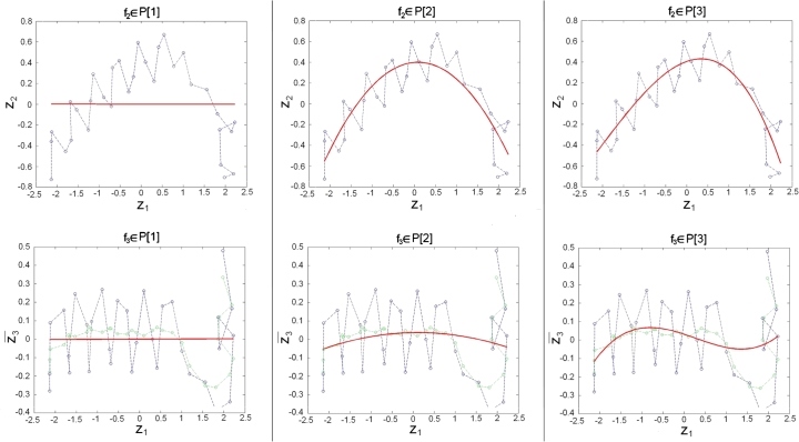
We determine for the functional form of the 1st vector component the identity function . In Fig. 1 we illustrate the 2nd vector component , representing the overall length of the α-helices, and the 3rd vector component . From this figure one can recognize that the periodic turns of the α-helices generate proportionally more noise in the 3rd vector component . Consequently we calculated a centered moving average [30] with period 4 according to
| (2.2) |
to remove the α-helicesʼ turns in the 3rd vector component (Fig. 1). We obtained from Eq. (2.1)
| (2.3) |
As functional forms, of our vector components, , , we considered polynomials and splines. Polynomials of degree m are defined as
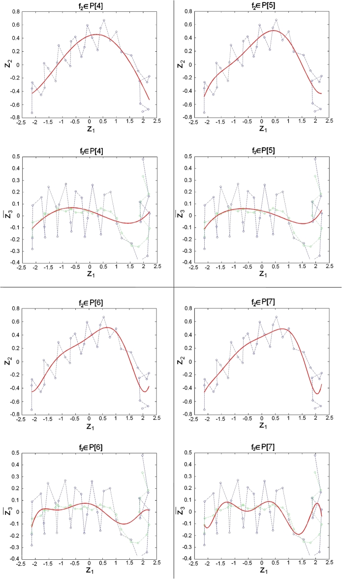
To define splines with N nodes we consider the set which yields a decomposition of the interval in subintervals , . The set of splines consists of smooth functions, which are polynomials of degree m on the subintervals . We will consider 21 different models to approximate and in Eq. (2.3), respectively. In particular we study polynomials (see Fig. 1), splines with node and splines with nodes, and in each case we let the polynomial degree vary within .
Fig. 1.
Projections of the α-helix of G-ALPHA of a pMH2 complex with the PDB accession code 3l6f: Transformed coordinates of -atoms are colored in blue. The moving average (Eq. (2.2)) of the 3rd vector component (Eq. (2.3)) is colored in green. The fitted polynomials of degrees 1 to 7 are colored in red. (For interpretation of the references to color in this figure legend, the reader is referred to the web version of this article.)
We employed the least-squares spline approximation algorithm from the Curve Fitting Toolbox of Matlab to fit the transformed data points of the vector components and by the above described models.
2.2. Model selection via information criteria for single stationary structures
Information criteria can be used to determine which models are most suitable to approximate given data. Usually there is a tradeoff between the goodness of fit and the complexity of a model, and information criteria typically incorporate penalties for the model size. To identify models which are suitable for describing our α-helices, we employed the corrected Akaike Information Criterion (cAIC) [16]:
| (2.4) |
Here SSE represents the Sum of Squared Error for the 2nd vector component and for the 3rd vector component; n is the number of data points and k is the number of model parameters. The 1st term of Eq. (2.4) corresponds to the negative maximum likelihood of the regression model, and decreases with model complexity. The 2nd term 2k is the penalty of the original Akaike Information Criterion (AIC), which obviously increases with model complexity. The final term (Eq. (2.4)) is a second-order correction of AIC for small sample sizes, which is recommended to be used when (see [2,16]). The criterion cAIC is computed for all 21 models, and those models with minimal cAIC are regarded as best.
For a more general comparison of results for different crystal structures, we calculated the cAIC-Differences [12] for each cAIC-value (Eq. (2.4)),
| (2.5) |
Consequently for the model which minimizes cAIC, but also other models with small might be considered as describing the data well. We refer to this procedure as “cAIC approach for the stationary case”.
2.3. Model selection via information criteria for whole trajectories of structures
Since dynamic trajectories over time yield deeper insight than single stationary structures, we extended our method to trajectories obtained from MD simulations. For this purpose we chose 4 exemplary structures from the PDB (see Section 2.5). On the basis of these structures we carried out MD simulations using Gromcas 4 [15] with the following settings:
We immersed each complex into an explicit artificial water bath allowing for a minimum distance of 20 Å between protein and box boundary. We applied periodic boundary conditions and minimized the energy of the complexes using the steepest descent method. Subsequently we warmed them up to 310 K. Finally we started MD simulations for a real time of 10 ns using the parameter sets approved by Omasits et al. [31]. On the basis of these simulations we investigated the effects of helical deformation on our spline models.
Each simulation consists of a sequence of stationary structures, hence the methodology for the stationary case can be applied for each time step of the MD simulations, resulting in 21 cAIC-Differences (see Eq. (2.5)) for every time step t of each simulation. As a result of the PCA applied to the α-helices, the functional form of the 2nd vector component is more stable than that of the 3rd vector component . Consequently the polynomial degree of the best model is stable over time for the 2nd vector component , whereas for the 3rd vector component one observes severe fluctuations. To deal with this instability we considered the performance of different functional forms over the whole time line. Specifically we added up the cAIC-Differences of Eq. (2.5) of each functional form over time
| (2.6) |
and favored those for which had a lower value. For the purpose of visualization of the cAIC-Differences we applied a robust version of local linear regression (Matlab function rlowess) using the Curve Fitting Toolbox of Matlab. We refer to this method as “cAIC approach for the dynamic case”.
2.4. Employed test set: stationary case
For the selection of an appropriate approximation of MH α-helices satisfying the balance between the goodness of fit and the complexity of a model, we applied the “cAIC approach for the stationary case”. For this purpose we extracted all 453 available crystal structures of (TR)/pMH complexes according to IMGT®, the international ImMunoGeneTics information system® [6,27] (accessed August 2011), from the PDB [1]. Out of this test set we excluded 10 complexes for reasons like incomplete helices or non-classical helices. This filtering yielded a test set of 443 crystal structures (Table 1).
Table 1.
Overview over the sets and the respective number of crystal structures. (The remaining complexes are omitted in the analysis, for the sake of completeness we added these complexes in this table.)
| MH1 | MH2 | Sum | |
|---|---|---|---|
| pMH | 323 | 24 | 347 |
| TR/pMH | 55 | 18 | 73 |
| Remaining complexes | 4 | 19 | 23 |
| Sum | 382 | 61 | 443 |
We classified these crystal structures first in MH class I (MH1) and class II (MH2). We then classified these complexes based on the absence of TR (pMH1, pMH2) or presence of TR (TR/pMH1 and TR/pMH2) in the crystal structures. A few crystal structures do not belong to one of these subsets, since their additional ligands are not TR (e.g. antibody pMH binding, natural killer cell receptor pMH binding, etc.). We collected these structures in Table 1 in the set of remaining complexes, but omitted them in our analysis. In total this leads to 4 subsets: pMH1, pMH2, TR/pMH1 and TR/pMH2 (Table 1).
2.5. Employed test set: dynamic case
We applied the “cAIC approach for the dynamic case” to our trajectories from MD simulations. For each of the first four sets in Table 1 we considered one MD simulation, with the following respective starting structures: PDB accession code 1hsa for pMH1, PDB accession code 1mi5 for TR/pMH1, PDB accession code 1sjh for pMH2 and PDB accession code 1fyt for TR/pMH2. In all cases we investigated which functional form has in an ε-neighborhood.
3. Results
3.1. Single stationary structures
In general, functional forms , corresponding to splines with 1 or 2 nodes have large cAIC-Differences . Therefore these models do not represent efficient α-helix approximations. The lowest cAIC-Differences were observed for polynomials, with different degrees for and .
In the first part of this section we will present the results for the MH1 and MH2 complexes. We will observe that the differences between the two MH-classes were reflected in the polynomial degree of models selected for the α-helices. In the second part of this section we will present results for the 2 subsets TR/pMH and pMH of each class investigating the influence of the TR binding at the α-helices.
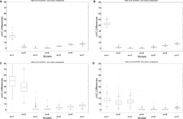
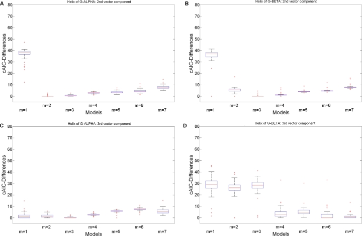
The boxplots of Figs. 2 and 3 illustrate the differences between MH1 and MH2 in terms of cAIC-Differences for polynomials (we illustrate all models including splines in Figs. S1 and S2 as supplementary data).
Fig. 2.
cAIC-Differences for the polynomial models over all crystal structures of MH1. (A) MH1 α-helix of G-ALPHA1: 2nd vector component . (B) MH1 α-helix of G-ALPHA2: 2nd vector component . (C) MH1 α-helix of G-ALPHA1: 3rd vector component . (D) MH1 α-helix of G-ALPHA2: 3rd vector component .
Fig. 3.
cAIC-Differences for the polynomial models over all crystal structures of MH2. (A) MH2 α-helix of G-ALPHA: 1st vector component . (B) MH2 α-helix of G-BETA: 1st vector component . (C) MH2 α-helix of G-ALPHA: 2nd vector component . (D) MH2 α-helix of G-BETA: 2nd vector component .
The best functional forms and resulting from our analysis for the MH1 are described in Table 2. Detailed information on the performance of different functional forms is provided as supplementary data in Table S1. From Fig. 2 and Table S1, we observe that for the 2nd vector component of both α-helices, as well as for the 3rd vector component of G-ALPHA1 [26] polynomials of degree 4 also perform well. In comparison, the 3rd vector component of G-ALPHA2 [26] requires a higher polynomial degree between and . Actually according to Table S1 the number of instances for which polynomials of degree 4, 5 or 6 perform best are almost identical. The number of the parameters for this functional form based on our method strongly depends on the angle of the kink in the α-helix; the more the enclosed angle is acute the higher is the resulting polynomial degree needed to approximate .
Table 2.
The functional forms and belonging to the vector-valued function (Eq. (2.3)) for the α-helices of MH1 (Fig. 2) and MH2 (Fig. 3) resulting from the “cAIC approach for the stationary case”.
| Single stationary structures |
||||
|---|---|---|---|---|
|
α-helix of G-ALPHA1 (MH1), G-ALPHA (MH2) |
α-helix of G-ALPHA2 (MH2), G-BETA (MH2) |
|||
| MH1 | 3 | 3 | 3 | 5 |
| MH2 | 2 | 3 | 3 | 6 |
In comparison to the MH1 complexes, the results for the MH2 complexes appear quite different (see Fig. 3): The best functional forms for these α-helices are again listed in Table 2. Figs. 3A, 3C and Table S2 provide more details. Thus for G-ALPHA [26], polynomials with degree 3 for the 2nd vector component are possible as well as polynomials with degree 2 for the 3rd vector component. For some instances a functional form is also a good approximation according to the cAIC-Differences , however we would not recommend this choice (see Section 4). The architecture of the α-helices of G-BETA [26] is slightly more complicated. Hence this structure requires polynomials with higher degrees. Apart from the functional forms given in Table 2 also (Fig. 3B) and (Fig. 3D) are appropriate.
In the second part of this section we will present results for the TR/pMH and pMH of each class. We performed the same descriptive statistic as used above. Corresponding figures and tables are presented as supplementary data (Fig. S3 for TR/pMH1, Fig. S4 for pMH1, Fig. S5 for TR/pMH2 and Fig. S6 for pMH2; the frequencies of TR/pMH1 and pMH1 are listed in Table S1 and the frequencies of TR/pMH2 and pMH2 in Table S2). The best functional forms are illustrated in Table 3.
Table 3.
The functional forms and belonging to the vector-valued function (Eq. (2.3)) for the α-helices of the pMH and TR/pMH of each MH class resulting from the “cAIC approach for the stationary case”.
| Single stationary structures |
||||
|---|---|---|---|---|
|
α-helix of G-ALPHA1 (MH1), G-ALPHA (MH2) |
α-helix of G-ALPHA2 (MH1), G-BETA (MH2) |
|||
| pMH1 | 3 | 3 | 3 | 5 |
| TR/pMH1 | 3 | 4 | 3 | 6 |
| pMH2 | 2 | 3 | 3 | 7 |
| TR/pMH2 | 2 | 3 | 3 | 6 |
Comparing the TR/pMH1 with pMH1, the results demonstrate that the polynomial degree of is the same in both α-helices. In the 3rd vector component the TR/pMH1 complexes showed a tendency to be approximated better with polynomials of higher degree (Figs. S3C and S3D). The best functional form of G-ALPHA1 is (Fig. S3C). Optional functional forms are and . The 3rd vector component of G-ALPHA2 required a functional form , however and are also suitable (Fig. S4D). These results show that the functional forms of the two domains are comparable in TR/pMH1 and pMH1 (Figs. S3 and S4). In summary the effect of the TR binding on the polynomial degree is rather small and insignificant. However, the effect of such binding will become noticeable in the coefficients of the model (see example in Section 4).
In Figs. S5 and S6 we illustrate the differences between TR/pMH2 and pMH2. Only the 3rd vector component of G-BETA showed minor differences. The complexes of pMH2 showed a tendency to a functional form . However, this effect is so small, that in general the functional forms of TR/pMH2 and pMH2 are the same. Similar to MH1 complexes, the effect of the TR binding at the α-helices will become noticeable in the coefficients of the model.
3.2. Dynamic structures
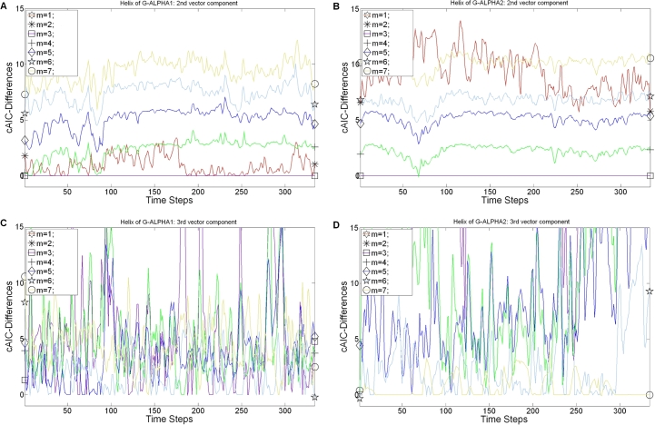
For our 4 MD simulations we applied the “cAIC approach for the dynamic case” (see Section 2), where we select the model for which (Eq. (2.6)) had the lowest value. Results for and are presented in Table 4. One illustrative example is given in Fig. 4, where we plotted the rlowess of the cAIC-Differences in each time step for polynomials (similar plot including splines is Fig. S7 in the supplementary data). We have shown for the single stationary case, that functional forms , corresponding to splines with nodes, yield in general larger cAIC-Differences , since they suffer from too many parameters. Consequently we consider here only polynomials for the vector components of our dynamic model.
Table 4.
The functional forms and belonging to the vector-valued function (Eq. (2.3)) for the α-helices of pMH and TR/pMH of each MH class resulting from the “cAIC approach for the dynamic case”.
Fig. 4.
rlowess of the cAIC-Differences belonging to the polynomial models over the time for the MH1 complex with the PDB accession code 1hsa. (A) MH1 α-helix of G-ALPHA1: 2nd vector component . (B) MH1 α-helix of G-ALPHA2: 2nd vector component . (C) MH1 α-helix of G-ALPHA1: 3rd vector component . (D) MH1 α-helix of G-ALPHA2: 3rd vector component .
Informations about other functional forms are listed in Table S3 for MH1 and Table S4 for MH2.
As we already mentioned in the Methods section (see Section 2), that the 2nd vector component is more stable than the 3rd vector component, which results from applying the PCA. Consequently the best model for the 2nd vector component has almost everywhere the same polynomial degree for the dynamic and the stationary structures (compare Section 3.1). The only differences to mention are polynomial degrees for the dynamic structures, that are almost always higher than for the single stationary structures. For example, pMH1 and TR/pMH1 need higher polynomials in the 3rd vector component for dynamics than for static structures.
In summary the results of the “cAIC approach for the dynamic case” are in line with the results of the “cAIC approach for the stationary case”: We found differences in the polynomial degrees in the functional forms for the α-helix of MH1 and MH2. We did not find any significant differences in the choice of the functional forms between TR/pMH and pMH, neither in the stationary case nor in the dynamic case. However, differences between helices become visible in the coefficients of the polynomials, as described in the example in the discussion.
3.3. Open interface for further analysis provided
The above described methodology is additionally supported by an open source code allowing the user to develop customized analysis procedures for the curves. Examples of such extensions are already provided in our implementation (see Appendix A) and discussed below.
4. Discussion
In this study we introduced splines to characterize the α-helix of the MH. Splines are a well-known concept in the context of molecular modeling where they were mainly used to visualize proteins in a convenient way (see Section 1). To our knowledge no method uses them to compare and investigate MH α-helices. Previously reported was the sequence-based IMGT/Collier-de-Perles tool [5,19] whose aim is also to make MH and their α-helices comparable. However, in contrast our method is entirely of structure-based origin. It will be of benefit to the community since in the literature one frequently reads sentences like: “After TR/peptide/co-receptor/superantigen binding the helix is deformed marginally/slightly/significantly/severely…”. These vague descriptions are difficult to interpret. Our method enables scientists to describe deformations in a structured, comparable and meaningful way.
Initially it sounds like a straight forward approach to characterize α-helix by curves. However, in this study several scientific challenges had to be addressed. The first question was to find an appropriate coordinate representation: We formulated a vector-valued function in parametric form consisting of polynomials and polynomial splines, since these functions are continuously differentiable. In our first approach we fitted the curves through coordinates of the α-helix obtained from the PDB. This procedure had the disadvantage that the approximations of the different α-helices were not comparable to each other, since the rotation and translation of the molecule complexes differ. In our second approach we used a rotation matrix to transform the α-helix into the diagonal of the Cartesian coordinate system. The advantage of this approach in comparison to our first fit was that the stationary structures were comparable to each other. However, in MD simulations we lost this advantage again, due to the movement over time. Consequently, in our third approach, we applied PCA to obtain a local coordinate system. After we established the different models with polynomials and splines with 1 or 2 nodes in combination with polynomials of degree 1 to 7 yielding 21 models on the basis of the PC, we used the cAIC to determine the most appropriate model for our α-helix. One representative example is depicted in Fig. 5.
Fig. 5.
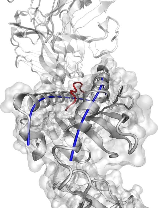
Visualization of a single stationary TR/pMH1 complex (PDB accession code 1mi5) with our recommended model according to Table 5.
The results, that polynomials are better approximations than splines, were quite surprising since the architecture of a single stationary α-helix is based on a model with polynomials or polynomial splines with one or two kinks (extremal values). However, during a MD simulation α-helices undergo conformational changes, which could not be represented by splines with nodes in a convenient way. One might consider further improvements for our splines. Instead of using equidistant nodes, the definition of the nodes at the kink points would be an improvement in the stationary case. The models would fit the α-helix more precisely. However, in the dynamic case one would have to define the nodes based on the first frame, yielding a very good model for this frame but not necessarily for others. During the simulation the kinks of the α-helix could shift, whereas the predefined nodes are fixed. This problem can be solved by redetermination of the nodes in every time step according to shifts of the kinks. This would lead to another more general approach where a dynamic search of the number of nodes and the location of these in each time step would be necessary. However, this redefinition would make the comparison over time difficult and lead to an exponential increase in computational time, rendering this approach impractical for longer MD trajectories. Hence the use of polynomials without nodes seems to be most appropriate (see recommendation in Table 5).
Table 5.
Recommended models.
| Single stationary structures |
Trajectories of structures |
|||||||
|---|---|---|---|---|---|---|---|---|
|
α-helix of G-ALPHA1 (MH1), G-ALPHA (MH2) |
α-helix of G-ALPHA2 (MH1), G-BETA (MH2) |
α-helix of G-ALPHA1 (MH1), G-ALPHA (MH2) |
α-helix of G-ALPHA2 (MH1), G-BETA (MH2) |
|||||
| MH1 | 4 | 4 | 4 | 5 | 4 | 7 | 4 | 7 |
| MH2 | 3 | 4 | 4 | 7 | 3 | 5 | 4 | 7 |
If the difference in the cAIC-Differences between models was found marginal we recommend using higher polynomials, particularly in the 2nd vector components, since this yields additional degrees of freedom and can fit α-helix during conformational changes more flexibly.
We do not recommend the polynomial , since linear functions are not flexible enough to guarantee good approximations for new complexes. The data show that for the α-helix of G-BETA (Table S4) the functional forms and are possible alternatives. In contrast to the results of the MH1 G-ALPHA2, the 2nd vector component of the α-helix of MH2 G-BETA needs a functional form with one higher polynomial degree. In this way the major differences [32] between the 2 MH classes are reflected in our results (see Section 3).
Furthermore our approach yielded interesting insights regarding the particular information on the α-helix which is represented in the different PC: (i) The plane spanned by the 1st and the 2nd PC contains the curvature of the α-helix. (ii) In the plane spanned by the 1st and the 3rd PC the torsion is described. Therefore the main information is found in the 2nd vector component and subtle information in the 3rd vector component.
Since there are hardly any differences in the selected functional forms between pMH and TR/pMH the same model can be applied, which is then suitable for calculating differences between complexes: The 2 MH2 complexes I–Ak (PDB accession code 1iak [10]) and I–Au (PDB accession code 1k2d [14]) differ by a helical displacement, as described by He et al. [14]. We applied our method to each complex yielding the same functional form as optimum (α-helix of G-ALPHA: , , α-helix of G-BETA: , ), but with different coefficients. Based on this we calculated the interhelical distances between curve approximation of the α-helix of G-ALPHA and the α-helix of G-BETA. The results nicely illustrate the displacement in a structured and meaningful way (Fig. 6A). The helical displacement toward the peptide of I–Au is characterized by the shallower curve of the interhelical distance. This effect becomes more visible in Fig. 6B showing the differences of the interhelical distances. To obtain a measure for this helical displacement, we calculated the approximation, using a triangulation, of the area of the ruled surface spanned by the two helices of each complex: The area of I–Ak amounts to 6.7255 nm2 and the area of I–Au amounts to 6.6575 nm2. The difference between these two areas is 0.068 nm2.
Fig. 6.

Helical displacement of MH2 I–Ak and I–Au. (A) The interhelical distances [nm] in each equidistant, discrete evaluation point of the curves (I–Ak is colored blue, I–Au is colored red). (B) The differences of the interhelical distances [nm] of these two complexes in each equidistant, discrete evaluation point of the curves. (For interpretation of the references to color in this figure legend, the reader is referred to the web version of this article.)
5. Conclusions
Altogether our method is a very general approach to model helices and can be applied to various parts of macromolecules to investigate their structural changes. Our method has potential applications for several areas of structural bioinformatics. For example, quantifying how α-helices rearrange in reaction to weak and strong MH binding peptides, binding processes by TR, co-receptors and superantigens. For this purpose our method provides models which can be evaluated with respect to differential geometric parameters like curvature, torsion and inter helical distances and spanned areas. In this way a convenient representation of the α-helices of the MH will be achieved yielding a big potential to shed light on the interaction mechanisms between MH and binding partners.
Acknowledgements
This study was supported by the Austrian Science Fund (FWF P22258-B12). Florian Frommlet was supported by Vienna Science and Technology Fund (WWTF MA 09-007a). We thank S. Hoellrigl-Binder, H. Havlicek and R. Karch for helpful discussions.
Footnotes
This paper and its associated computer program are available via the Computer Physics Communications homepage on ScienceDirect (http://www.sciencedirect.com/science/journal/00104655).
Supplementary material related to this article can be found online at doi:10.1016/j.cpc.2012.02.008.
Appendix A. Availability
The whole software, entitled MH2c, for the choice of the functional forms and simple examples for the characterization of arbitrary helices are available for free for academic researchers. The software package is implemented in Matlab version 7 and therefore available as platform independent source code from: http://www.meduniwien.ac.at/msi/md/sourceCodes/mhHelices/mhHelices.htm.
Appendix B. Supplementary material
The following is the Supplementary material related to this article.
Supplementary data for MH2c: Characterization of major histocompatibility α-helices – an information criterion approach.
References
- 1.Bergman H.M., Westbrook J., Feng Z., Gilliland G., Bhat T.N., Weissig H., Shindyalov I.N., Bourne P.E. Nucleic Acids Res. 2000;28:235–242. doi: 10.1093/nar/28.1.235. [DOI] [PMC free article] [PubMed] [Google Scholar]
- 2.Burnham K.P., Anderson D.R. Wildlife Res. 2001;28:111–119. [Google Scholar]
- 3.Choudhuri K., van der Merwe P.A. Semin. Immunol. 2007;19:255–261. doi: 10.1016/j.smim.2007.04.005. [DOI] [PubMed] [Google Scholar]
- 4.Clamp M.E., Cuff J., Searle S.M., Barton G.J. Bioinformatics. 2004;20:426–427. doi: 10.1093/bioinformatics/btg430. [DOI] [PubMed] [Google Scholar]
- 5.Ehrenmann F., Giudicelli V., Duroux P., Lefranc M.P. Cold Spring Harb. Protoc. 2011;2011:726–736. doi: 10.1101/pdb.prot5635. [DOI] [PubMed] [Google Scholar]
- 6.Ehrenmann F., Kaas Q., Lefranc M.P. Nucleic Acids Res. 2010;38:D301–D307. doi: 10.1093/nar/gkp946. [DOI] [PMC free article] [PubMed] [Google Scholar]
- 7.Ehrenmann F., Lefranc M.P. Cold Spring Harb. Protoc. 2011;2011:750–761. doi: 10.1101/pdb.prot5637. [DOI] [PubMed] [Google Scholar]
- 8.Elsner H.A., DeLuca D., Strub J., Blasczyk R. Bone Marrow Transplant. 2003;33:165–169. doi: 10.1038/sj.bmt.1704301. [DOI] [PubMed] [Google Scholar]
- 9.Enkhbayar P., Kamiya M., Osaki M., Matsumoto T., Matsushima N. Proteins. 2004;54:394–403. doi: 10.1002/prot.10605. [DOI] [PubMed] [Google Scholar]
- 10.Fremont D.H., Monnaie D., Nelson C.A., Hendrickson W.A., Unanue E.R. Immunity. 1998;8:305–317. doi: 10.1016/s1074-7613(00)80536-1. [DOI] [PubMed] [Google Scholar]
- 11.Frishman D., Argos P. Proteins. 1995;23:566–579. doi: 10.1002/prot.340230412. [DOI] [PubMed] [Google Scholar]
- 12.Ghosh J.K., Samanta T. Current Sci. 2001;80:1135–1144. [Google Scholar]
- 13.Gorielyn A., Hausrath A., Neukirch S. Biophys. Rev. Lett. 2008;3:77–101. [Google Scholar]
- 14.He X.L., Radu C., Sidney J., Sette A., Ward E.S., Garcia K.C. Immunity. 2002;17:83–94. doi: 10.1016/s1074-7613(02)00340-0. [DOI] [PubMed] [Google Scholar]
- 15.Hess B., Kutzner C., van der Spoel D., Lindahl E. J. Chem. Theory Comput. 2008;4:435–447. doi: 10.1021/ct700301q. [DOI] [PubMed] [Google Scholar]
- 16.Hurvich C.M., Tsai C.L. Biometrika. 1989;76:297–307. [Google Scholar]
- 17.Huseby E.S., White J., Crawford F., Vass T., Becker D., Pinilla C., Marrack P., Kappler J.W. Cell. 2005;122:247–260. doi: 10.1016/j.cell.2005.05.013. [DOI] [PubMed] [Google Scholar]
- 18.Kaas Q., Duprat E., Tourneur G., Lefranc M.P. Springer; New York, USA: 2008. Immunoinformatics. pp. 19–49. [Google Scholar]
- 19.Kaas Q., Ehrenmann F., Lefranc M.P. Brief. Funct. Genomics Proteomics. 2007;6:253–264. doi: 10.1093/bfgp/elm032. [DOI] [PubMed] [Google Scholar]
- 20.Kaas Q., Lefranc M.P. In Silico Biol. 2005;5:505–528. [PubMed] [Google Scholar]
- 21.Kabsch W., Sander C. Biopolymers. 1983;22:2577–2637. doi: 10.1002/bip.360221211. [DOI] [PubMed] [Google Scholar]
- 22.Karplus M., McCammon J.A. Nat. Struct. Biol. 2002;9:646–652. doi: 10.1038/nsb0902-646. [DOI] [PubMed] [Google Scholar]
- 23.Knapp B., Omasits U., Bohle B., Maillere B., Ebner C., Schreiner W., Jahn-Schmid B. Mol. Immunol. 2009;46:1839–1844. doi: 10.1016/j.molimm.2009.01.009. [DOI] [PubMed] [Google Scholar]
- 24.Knapp B., Omasits U., Schreiner W., Epstein M.M. PLoS ONE. 2010;5:e11653. doi: 10.1371/journal.pone.0011653. [DOI] [PMC free article] [PubMed] [Google Scholar]
- 25.Koh E., Kim T., Cho H.S. Bioinformatics. 2006;22:297–302. doi: 10.1093/bioinformatics/bti775. [DOI] [PubMed] [Google Scholar]
- 26.Lefranc M.P., Duprat E., Kaas Q., Tranne M., Thiriot A., Lefranc G. Dev. Comp. Immunol. 2005;29:917–938. doi: 10.1016/j.dci.2005.03.003. [DOI] [PubMed] [Google Scholar]
- 27.Lefranc M.P., Giudicelli V., Ginestoux C., Jabado-Michaloud J., Folch G., Bellahcene F., Wu Y., Gemrot E., Brochet X., Lane J., Regnier L., Ehrenmann F., Lefranc G., Duroux P. Nucleic Acids Res. 2009;37:D1006–D1012. doi: 10.1093/nar/gkn838. [DOI] [PMC free article] [PubMed] [Google Scholar]
- 28.Lopera J.A., Sturgis J.N., Duneau J.P. J. Mol. Graph. Model. 2005;23:305–315. doi: 10.1016/j.jmgm.2004.10.004. [DOI] [PubMed] [Google Scholar]
- 29.Mohapatra P.K., Khamari A., Raval M.K. J. Mol. Model. 2004;10:393–398. doi: 10.1007/s00894-004-0212-y. [DOI] [PubMed] [Google Scholar]
- 30.Montgomery K.T. Wiley; New York: 2001. Introduction to Statistical Quality Control. [Google Scholar]
- 31.Omasits U., Knapp B., Neumann M., Steinhauser O., Stockinger H., Kobler R., Schreiner W. Mol. Simul. 2008;34:781–793. [Google Scholar]
- 32.Rudolph M.G., Stanfield R.L., Wilson I.A. Annu. Rev. Immunol. 2006;24:419–466. doi: 10.1146/annurev.immunol.23.021704.115658. [DOI] [PubMed] [Google Scholar]
- 33.Thomas D.J. J. Mol. Graph. 1994;12:146–152. doi: 10.1016/0263-7855(94)80079-0. [DOI] [PubMed] [Google Scholar]
- 34.Varani L., Bankovich A.J., Liu C.W., Colf L.A., Jones L.L., Kranz D.M., Puglisi J.D., Garcia K.C. Proc. Natl. Acad. Sci. USA. 2007;104:13080–13085. doi: 10.1073/pnas.0703702104. [DOI] [PMC free article] [PubMed] [Google Scholar]
Associated Data
This section collects any data citations, data availability statements, or supplementary materials included in this article.
Supplementary Materials
Supplementary data for MH2c: Characterization of major histocompatibility α-helices – an information criterion approach.


