Abstract
Meniscus efficacy at promoting joint congruity and preventing osteoarthritis hinges on enthesis integrity Gross-scale tensile testing, histomorphometry, and magnetic resonance imaging reveal significant differences between the four attachments, implicating that each must endure a unique mechanical environment thereby dictating their structure. However, little data exists to elucidate how these interfaces have adapted to their complex loading environment, particularly on a relevant scale as the enthesis transitions through several unique zones in less than a millimeter. In our study we leveraged nano-indentation to determine viscoelastic material properties through the transition zones. Additionally, we employed histological techniques to evaluate enthesis structure including collagen organization and interdigitation morphometry. Mechanical evaluation revealed the medial posterior insertion site to be significantly more compliant than others. Collagen fiber orientation and dispersion as well as interdigitation morphometry was significantly different between attachments sites. These findings are clinically relevant as a disproportionate amount of enthesis failure occurs in the medial posterior attachment. Also, meniscal enthesis structure and function will need to be considered in future reparative and replacement strategies in order to recreate native meniscus mechanics and prevent osteoarthritis propagation.
Keywords: Insertion, enthesis, collagen fiber orientation, viscoelastic
1. Introduction
Classically defined by the thinning of articular cartilage, knee osteoarthritis (OA) entails a complex series of events attributed to either trauma or progressive degeneration. Increasing evidence has identified various joint structures as potential disease-initiating pathways, including cartilage, bone, ligaments, synovial fluid, and the meniscus [1]. The latter, which has historically been surgically triaged post-injury, is now known to be crucial in maintaining joint health and preventing OA [2]. Currently, treatment of menisci-derived OA using surgical intervention via repair, meniscectomy, or allograft replacement can be implemented; however, this can fail to halt OA progression [3, 4]. While diagnosis of meniscal injury and subsequent treatment are significantly more successful in younger patients [5], patients with identifiable meniscal damage increases with age, posing a serious physical and monetary burden [6]. One hope is that tissue engineered replacements will provide an alternative modality for individuals with severe meniscal degeneration and decrease the onset and progression of OA. In both donor and engineered replacements, particular attention is paid to the meniscal body itself. However, several studies have stressed the importance of meniscal attachments [7–9]. These studies have encouraged natural reconstruction of the meniscus to bone interface in order to prevent pathological contact pressures, load transmission, and excessive meniscal translation, a known indicator of OA [10]. While soft-tissue to bone tissue engineering is a thriving field of research, little attention has been paid to the meniscus to bone interface.
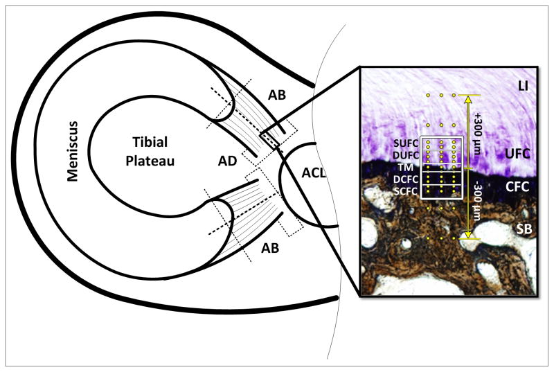
The main bodies of the menisci consist of fibrocartilaginous semi-lunar structures that are triangular in cross-section. This shape aids in joint alignment and cushioning by transducing applied compression to hoop stresses which are attenuated at the tibial plateau via fibrocartilaginous (FC) entheses [11–13]. These sites are located at the medial anterior (MA), lateral anterior (LA), medial posterior (MP), and lateral posterior (LP) portions of the menisci. As the main body of the meniscus transitions to bone, the superficial, randomly oriented and radial tie collagen fibers of the meniscal body diminish, leaving primarily ligament-like aligned type I collagen fibers [14]. These fibers demonstrate a crimped patterning and are responsible for bearing tensile loads developed from hoop stresses [8]. The ligamentous region (LI) extends from the body of the meniscus and transitions into the tibial plateau via uncalcified fibrocartilage (UFC) and calcified fibrocartilage (CFC). The UFC region contains primarily types I and II collagen fibers that are continuous across a calcification front known as the tidemark (TM) and transition into the CFC [15]. Changes in the depth and thickness of the TM can be indicative of pathophysiology, although little is known of its definitive purpose [16, 17]. Lastly, the CFC meets subchondral bone [SB) at an interdigitated cement line (Figure 1) [18, 19]. Developmental studies demonstrate that type I collagen fibers must be continuous through the enthesis at least until this junction [20]. Other forms of collagen are found in FC insertions, but in much smaller quantities, and the mechanical behavior of this transitional tissue is mostly dependent on contributions of type I and II collagens [21].
Figure 1.
Schematic of sample extraction and analysis regions. Dotted lines represent cut surfaces. Adaxial (AD) sections were used for collagen fiber orientation and interdigitation analyses, abaxial (AB) sections were used for mechanical evaluation. Inset shows the unique zones of the meniscal attachments: Ligamentous (LI), Uncalcified Fibrocartilage (UFC), Calcified Fibrocartilage (CFC), and Subchondral Bone (SB). The regions of fibrocartilage are separated by the tidemark (TM). Boxed region represents areas used for polarized light analysis (SUFC – Superior UFC, DUFC – Deep UFC, DCFC – Deep CFC, S – Superior CFC). Dots represent location of mechanical evaluation using nanoindentation. Indentation was performed in a region 300μm above and below the TM. Section is stained using toluidine blue and counter stained using Von Kossa technique.
The presence and amount of FC at insertion sites can be attributed to compressive and shear loads as well as insertion angle changes during joint movement [18, 22, 23]. Specifically, the UFC region is considered analogous to a rubber grommet on an electrical plug, shielding the insertion site from compression, while the CFC region protects the bone from shear loads [23]. In the context of the meniscal attachments, the femoral condyles may also be applying direct compressive and shear forces to some or all the insertion sites throughout the gait cycle. Magnetic resonance imaging (MRI) evaluation of meniscal translation, mechanical testing, and histological evaluation of the attachments has revealed significant differences between the sites, elucidating that each are dependent on the loading environment unique to their location [9, 18, 19, 24]. In particular the anterior sites possess significantly greater failure properties than the posterior insertion sites.
In this study we aim to quantitatively define the structure and mechanical function of the human meniscal attachments using nanomechanical and histomorphological techniques. Based on previous research, we hypothesized that the anterior collagen fiber insertion angles would be shallower, relative to the tidemark, and more organized, resulting in superior mechanical performance.
2. Materials and methods
2.1. Sample preparation
Eight cadaver knees (ages 41–61, average age: 55) were obtained from the Mayo Clinic tissue donor program with institutional review board approval. X-ray evaluation prior to dissection as well as gross evaluation of soft-tissue prior to testing/embedding was performed by an orthopaedic surgeon to ensure healthy samples. Bone blocks were excised to include meniscal attachment sites from the tibial plateau and bisected along the axis of collagen fiber insertion. Regular wetting using phosphate buffered saline (PBS) was used to keep tissue moist during processing. Each half of the attachment sites were wrapped in PBS soaked gauze and stored sealed at −20°C until further processing for either structural evaluation or mechanical testing.
2.2. Histology
Adaxial sections were utilized for histological analysis (Figure 1). Attachments were fixed in 10% neutral buffered formalin for 48 hours, serial dehydrated in ethanol, defatted in xylene and then embedded in methyl methacrylate (Technovit 9100 New, Heraeus Kulzer GmbH, Wehrheim, Germany). Sections were made (30μm thick) using standard cutting and grinding techniques. Collagen fiber orientation sections were decalcified and stained with 0.1% picrosirius red. Interdigitation sections were stained using von Kossa and counterstained with toluidine blue.
2.3. Collagen fiber orientation
Exploiting the enhancement of collagen fiber birefringence by sirius red allowed for determination of collagen fiber angles by utilizing polarized light analysis [25]. Stained sections were imaged using a microscope (Olympus BX51P) equipped with rotating polarizer and analyzer, a quarter wavelength compensator, and digital camera (DP70). The slides were placed between the polarizer (east-west position) and analyzer (north-south position) and aligned with the TM horizontal (along the 0–180° plane) so that all angular measurements were in reference to the TM. Images were obtained for sample orientations at 10° increments between 45° and 135° with and without the compensator (northwest-southeast position) in place.
A custom Matlab graphical user interface [26], was used to determine the fiber extinction angle. The software interface was used to select the tidemark and build a grid of measurement points above and below this feature. A plot of linearly polarized light intensity as a function of sample orientation was generated at each measurement point. The collagen fiber angle was determined from the angle corresponding to the minimum light intensity. To characterize the fiber angle across the insertion site, the measurement grid was subdivided into 5 sub-regions, described by their proximity to the tidemark: superior uncalcified fibrocartilage (SUFC), deep uncalcified fibrocartilage (DUFC), tidemark (TM), deep calcified fibrocartilage (DCFC), superior calcified fibrocartilage (SCFC) (Figure 1). Angular mean and variance for each sub-region were calculated using the Matlab circular statistics toolbox [27]. For examining fiber dispersion/organization, angular deviation was inclusive of all fiber angles. Individual attachment sites in each sub-region were compared using a Watson-Williams test (p < 0.01).
2.4. Interdigitation Analysis
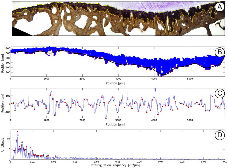
To analyze the interdigitated joining of fibrocartilage to bone the CFC region is first isolated using the ImageJ color deconvolution tool [28]. The resultant 8-bit single color image is then thresholded and all extraneous points are removed. The resultant binary pixels are then stored as discrete X & Y locations. A function defining the interface is generated by taking the minimum y-pixel value at each unique x-location. To simplify the analytical process the “drift” that is due to the anatomical shape of the insertion must be removed. This is accomplished by applying a coarse Savitzky-Golay smoothing function [29] to the interdigitation function and subtracting it from the original function (Figure 2).
Figure 2.
Example of interdigitation analysis performed. A) To identify the calcified fibrocartilage (CFC) region the insertion site was stained with toluidine blue and counter stained using Von Kossa technique. The CFC region (outlined in yellow) was isolated using the ImageJ color deconvolution tool. B) Pixel locations were loaded into Matlab and a coarse Savitzky-Golay smoothing function is overlaid (black line) at the cement line between CFC and subchondral bone. C) The smoothing function was then subtracted from the pixels at the cement line yielding unique x,y coordinates representing the interdigitations. Interdigitation size and average frequency was then computed using custom written scripts determine the nearest neighbor peak/valley pairs. Size is the height difference between pairs. Average frequency is the total number of interdigitations determined along the insertion site. D) A fast Fourier transform was then applied to the data to determine the peak and high frequency of interdigitation.
The complex interdigitations were defined using the average size, average-, most dominant-, and highest- frequency. A Matlab built-in function (findpeaks()) was used to identify the peaks/valleys of the interdigitation function. The average size of the interdigitations were ascertained by first determining the closest peak/valley pairs, with a pre-determined spacing and height threshold to remove any data “jitter”. An assessment algorithm sought through all valleys and peaks and determined the nearest neighbor. The difference in height between the two points was then computed. For a given sample the mean amplitude was then computed across the whole insertion site. Average frequency was determined from the number of peak/valley pairs over the length of the whole insertion site. As the interdigitations are inhomogeneous across the site, it is an oversimplification to define only a single frequency value, so more spectral data was required to fully define the interface. The interdigitation function was transformed to the frequency domain using a Fast Fourier Transform to identify the most dominant and highest frequency components. Results were compared using a student’s t-test (p < 0.05).
2.5. Nano-indentation
2.5.1. Testing
Abaxial sections were prepared for mechanical evaluation. Samples were thawed, rinsed in PBS, and placed cut surface up in mounting molds to allow for the insertion to be properly indented. A high viscosity acrylic resin that did not penetrate the specimen (ClaroCit, Struers Inc., Cleveland, OH) was then poured into the mold, without touching the cut surface, and allowed to fully cure. The exposed indentation surface was then series ground flat along the insertion fiber axis, so as to prevent fraying of soft-tissue, using 600- and 1200-grit silicon carbide paper with constant distilled water lubrication [30].
Embedded specimens were indented using a 300μm spherical ruby tip (Agilent Technologies, Inc., Santa Clara, CA) at 45 discrete locations (3 columns × 15 rows aligned from the TM). It should be noted that while the tip is relatively large compared to the insertion constituents, actual penetration depth resulted in a contact radius of less than 50 μm. Indentation locations were chosen by first locating the apparent TM separating the calcified and uncalcified fibrocartilage then mapping 7 indents above and below the tidemark at varying distances (Figure 1 inset).
Selection was based upon previous histological data as discerning the four unique zones is not possible using the basic light microscope installed on the nano-indentation test machine. The primary region of interest was at the immediate proximity to TM, and indent spacing was finer closer to and sparser further away from the TM. Three adjacent columns, separated by 50μm, were indented so as to capture the variability in material properties due to the highly interdigitated calcified fibrocartilage to subchondral bone interface [18, 19]. Indentation location order was randomized and specimens were kept moist with 0.9% saline during testing.
A variable maximum load of either 10-, 5-, or 1-mN was applied, depending if the presumed indentation location was subchondral bone, calcified fibrocartilage, or uncalcified fibrocartilage/ligamentous, respectively. The changing load is factored into the analytical model used, as discussed in the following section, and is thus accounted for [31]. The load was held for 100 seconds in order to exhaust time dependent behavior as determined through pilot testing.
2.5.2. Processing
Displacement time histories for the load-hold period were fit to a linear viscoelastic indentation model [31, 32] using a constrained trust-region reflective optimization algorithm. Instantaneous and steady-state shear moduli were extracted from the fitting process. The robust model accounted for the effect of material creep during load ramping, indenter geometry, and the variable applied load. The model assumption of isotropy was corrected using Gν = 2Gl (1−ν) assuming a Poisson’s ratio of ν = 0.3 [33, 34]. Lastly, shear moduli were converted to elastic moduli using E = 2G(1+ν). Model fits were evaluated using a t-test to compare mean standardized variance between the model and experimental data (p < 0.01) [35]. Indents that “failed,” either due to an optimization or testing anomaly, were rejected and replaced with a interpolated value based on one-dimensional piece-wise cubic interpolation. Material elastic fraction was evaluated using the ratio of steady-state and instantaneous moduli [36]. Modulus disparities due to the joining of the dissimilar mineralized and unmineralized zones were assessed using the slope of the elastic moduli across the tidemark. This metric provides an indicator of the mechanical gradient across the insertion site. Due to the variability of zonal constituents and shortcoming of using a basic light microscope to select indentation points, a custom written MATLAB script determined the optimal points to include in slope determination. The processing algorithm optimized indentation locations to determine best linear fit for points within 100 μm of TM. Remaining points not included in the slope fitting process were grouped into hard tissue and soft tissue and averaged accordingly. Material parameters were compared using a two-factor ANOVA (attachment site, indent location). Explicit differences were elucidated post-hoc using Tukey’s method (p < 0.01). Modulus disparities were compared between the anterior and posterior for each meniscus using paired t-tests (p < 0.05).
3. Results
3.1. Collagen fiber orientation
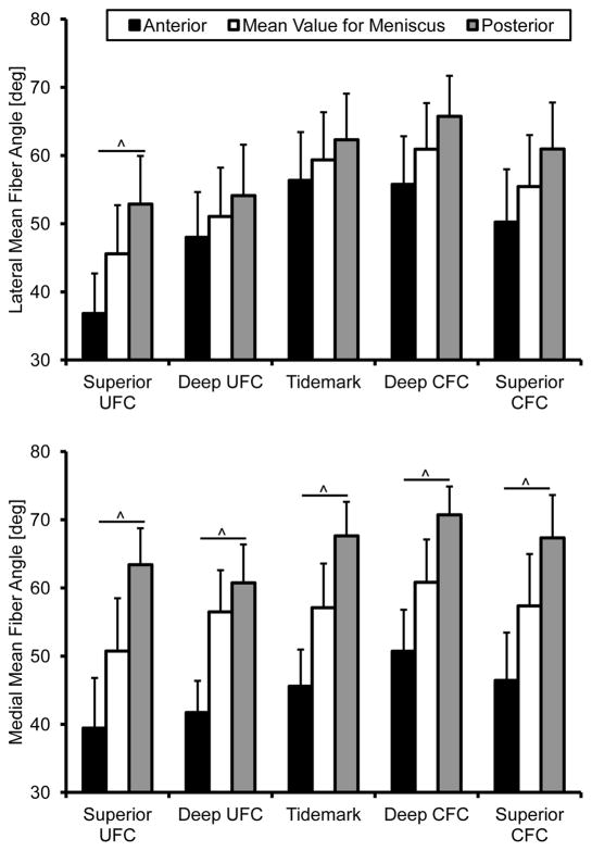
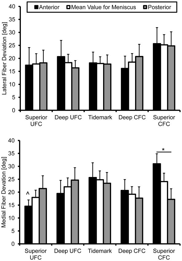
Structural analysis revealed the presence of interwoven fibers throughout the insertion sites (Figure 3). These fibers, not atypical of FC entheses [17], were ignored by removing angles greater than 90°. This effectively removed skewing of the mean for the primary fiber direction due to the woven fibers. The angular cutoff was determined by examining the resultant histograms generated from this analysis. Removing these fibers and determining the primary mean fiber angle direction revealed significant differences between attachments. The collagen fibers of the medial anterior attachment inserts into the bone at significantly shallower angles than the posterior, relative to the tidemark, throughout the entire interface (Figure 3). In the lateral attachment sites this was only true for the SUFC region. Fiber dispersion was significantly different within and between attachment sites. Specifically, the medial anterior attachment site significantly increased in dispersion between the SUFC and SCFC. Additionally, the medial anterior site was significantly more disperse than the posterior in the SCFC region (Figure 4).
Figure 3.
Mean collagen fiber orientation through the meniscal insertions. The medial attachment sites were significantly different from one another throughout the entire interface. The lateral attachment sites fiber angle was only significantly different in the superior uncalcified fibrocartilage zone. Mean ± standard error. (^ - p < 0.01)
Figure 4.
Collagen fiber deviation through the meniscal insertions. Medial anterior fiber dispersion significantly increased from the superior uncalcified fibrocartilage to the superior calcified fibrocartilage. Fiber dispersion was significantly greater in the medial anterior superior calcified fibrocartilage region than the medial posterior. Mean ± standard error (^ - s.d. from medial anterior SCFC p < 0.01, * - p < 0.05)
3.2. Interdigitation Analysis
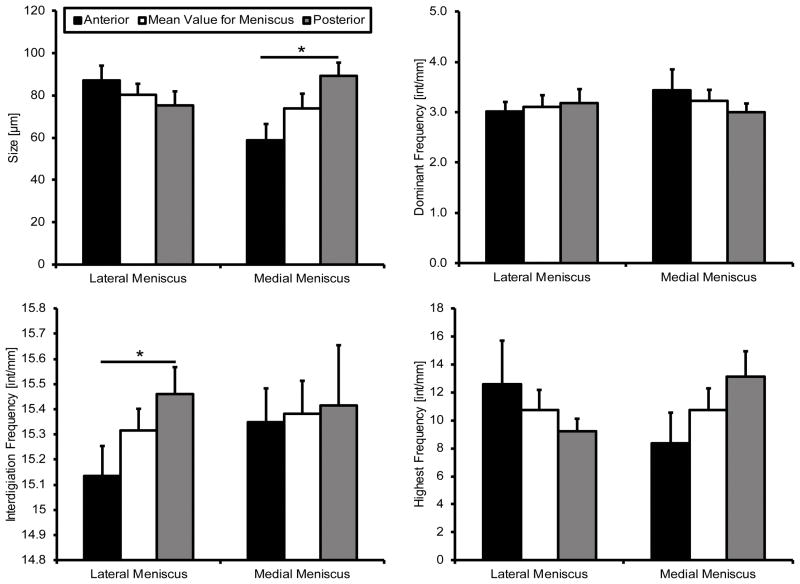
Interdigitation size was found to be significantly different in the medial compartment, with the posterior being significantly larger than the anterior (Figure 5). No significant differences were identified in the lateral compartment, or between compartments. The average frequency of interdigitations was found to be approximately 15.4 interdigitations per millimeter for both menisci. There was a significant difference between the anterior and posterior in the lateral compartment, however the medial appeared to be similar between attachment regions (Figure 5). The most dominant frequency is a low interdigitation oscillation of approximately 3–3.5 interdigitations per millimeter (Figure 5). The highest frequency observed varied between sites, however there was no identified significant difference between attachment or meniscus (p < 0.05).
Figure 5.
Interdigitation geometry. The medial posterior was significantly larger than the anterior. Average interdigitation frequency was significantly higher in the lateral posterior than the lateral anterior. Determination of most dominant and highest frequencies did not yield any significant differences between attachment sites. Mean ± standard error. (^ - p < 0.01)
3.3. Nano-Indentation
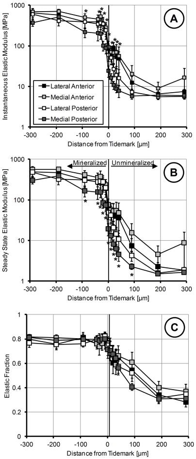
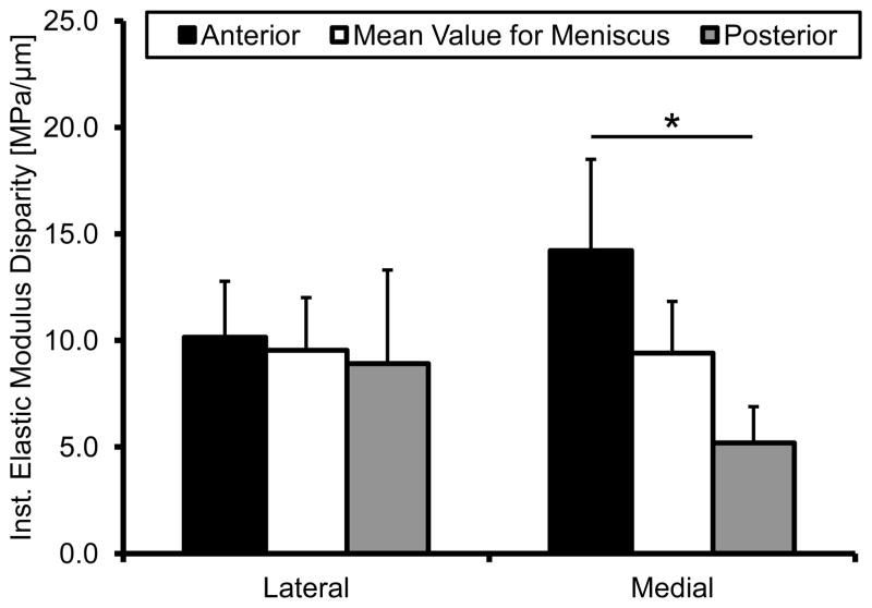
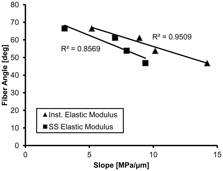
Mechanical evaluation of the insertions using nano-indenation elucidated that the medial posterior attachment is significantly more compliant for both instantaneous and steady-state behavior (Figure 6A&B). While there was an apparent difference in elastic fraction between soft and hard tissue, particularly towards the LI portion of the insertion, this behavior was consistent among attachments (Figure 6C). Instantaneous elastic modulus disparities were significantly different between the medial meniscus attachments, with the posterior having the lowest disparity between the soft and hard tissue (Figure 7). No significant differences were identified in the lateral meniscus. The mean fiber angle appeared to be inversely correlated with the slope of the instantaneous modulus (R2=0.9505); however this was inferiorly correlated for steady-state behavior (R2=0.8569) (Figure 8).
Figure 6.
Mechanical properties of the meniscal insertions determined using nano-indentation. X-axis represents distance from the tidemark with positive values towards the ligamentous region and negative towards the subchondral bone. A) Instanteous elastic modulus of the four attachment sites. Medial posterior was significantly more compliant than all other insertions, particularly in the fibrocartilage regions. B). Steady-state elastic modulus of the four attachment sites. Medial posterior was significantly more compliant than all other insertions, specifically in the fibrocartilage regions. C). Elastic fraction of the attachment sites. Mineralized regions were more elastic while unmineralized were more viscous. There were no significant differences for elastic fraction between insertions. Mean ± standard error. (* - locations are significantly different from the medial posterior, p < 0.05)
Figure 7.
Modulus disparity at each meniscal attachment site as determined by the slope of the instantaneous elastic modulus. The medial anterior and posterior insertions were significantly different from one another. Mean ± standard error. (* - p < 0.05)
Figure 8.
Linear correlation between the modulus disparity and the mean fiber angle across the tidemark.
4. Discussion
This research documents for the first time the quantitative differences in structure and function within and between the human meniscal attachment sites. Our results agreed with the hypothesis that the anterior attachment sites would have a more acute insertion angle and be mechanically superior to the posterior.
Meniscus mobility may shape fiber insertion angle as MRI investigation of meniscus translation during deep knee flexion has shown that the anterior horns undergo significantly greater translation than the posterior and remain flatter to the tibial plateau [37]. Accordingly, posterior fiber insertion angles were found to be more direct, with respect to the tidemark, potentially indicative of the limited displacement during knee flexion. Contrary to findings in tendon enthesis, fiber angle dispersion of the meniscal attachments was rarely significantly different between the zones examined here [26]. However, the regions examined here were smaller than that quantified in the aforementioned study which focused on the supraspinatus of a rat. Previous qualitative examination of the ligamentous region of the meniscal attachments does reveal a highly aligned network [14] which would suggest a similar transition from highly to a more disperse collagen fibril network. This structural organization is thought to be a mechanical adaptation to attenuating different modes of loading that the insertion site is subjected to [17, 21, 26, 38]. Notably, overall fiber deviation of the meniscal attachments appears more disperse than the tendon enthesis perhaps indicating different loading mechanisms between passive and active force transmitters.
To encapsulate the high degree of compositional variability at the interface, nano-indentation techniques were used to facilitate direct mechanical testing. Additionally, for data analysis the typical goodness of fit metric R2 was not utilized as it can be misleading in the context of multi- parameter non-linear least squares optimization. Results here agreed with previous biomechanical evaluation on the macro- and nano-scale of meniscal attachments that the anterior attachment sites are significantly stronger than the posterior [24, 30]. This work expounded on the previous nano-scale study by comparing each attachment site individually and identifying that the medial posterior is weakest. Comparing these results with tensile data that examined the strain distribution between the bone and meniscus shows a similar trend for data acquired at the middle of the bony insertion [24]. The anterior attachments appear to be stiffer than the posterior and explicitly the medial posterior, again, appears to be more compliant. Within the attachment sites, nano-indentation demonstrated an increasing amount of material time-dependency when transitioning from the calcified regions to the uncalcified regions. This is to be expected as the response of the soft-tissue is heavily influenced by the presence hydrophilic proteoglycans [41].
As structure can directly, though not solely, influence function the relative fiber angle was shown to be inversely correlated with relative change in modulus across the TM. More direct insertion angles appear to result in lower stress concentrations, indicated by a lower elastic modulus slope. Additionally, increased fiber organization has been shown to improve tensile mechanics for various biological tissues [26, 42, 43]. Increased interwoven fibers may enhance the compressive mechanical properties for the meniscal attachments. This effect is analogous to woven fiber composites that are reduced in compressive strength when fibers are clustered together [44]. The high fiber dispersion in the anterior sites, particularly the medial anterior may be an adaptation to the high compressive forces generated during load due to the more acute insertion angle [16, 17]. This is similar to the randomly oriented network of collagen fibers at the surface of articular cartilage [45]. It must be recognized, however, that other constituents play an important role in dictating biomechanical performance of entheses aside from collagen fiber orientation, including but not limited to: fiber cross-linking, mineralization, and proteoglycans [38, 46]. Continued evaluation and comparison of various insertion tissue mechanics using nano- and micro-scale testing would aid in elucidating how the various structural and compositional variants lend to specific enthesis efficacy.
Interdigitation size data trends closely resemble the findings of Benjamin et. al. when examining total cortical calcified tissue thickness (defined as the calcified fibrocartilage and lamellar bone layer until the trabeculae) [18]. Likely, cortical thickness has been dictated by the unique mechanical demands of each attachment site and, along with interdigitated interfacing with CFC, lends to overall enthesis functionality. Interdigitation size reported by Villegas et al., however, are much larger (up to an order of magnitude) than data presented here, however, investigation was performed on bovine tissue, which possess much larger menisci and attachment sites [19]. Interestingly, the medial posterior and lateral anterior appear to have the most “jagged” interdigitations, as exhibited by the high frequency. In the particular case of the medial posterior this may be an adaptation to increase adjoining surface area between the mineralized fibrocartilage and subchondral bone in order to sustain the potentially high degree of loading at this site.
These results are clinically relevant due to the higher prevalence of medial posterior horn and root injuries [39, 40, 47, 48], which coincides with the nano-indentation result indicating a more compliant attachment site. In radial tearing of the medial posterior horn it is hypothesized that deep flexion leads to compartmental impingement and subsequent tear initiation [37, 47], which may be exacerbated by the mobility of the attachment site. In traumatic tearing or root avulsion the insertion may fail to cope with pathological loading as readily as the remaining meniscal attachments.
Evaluation of the meniscal attachments provides the unique opportunity to examine four similar, yet distinct, entheses as compared to other soft tissue to bone insertions. The attachment sites were shown to be both structurally and functionally unique as well as heterogeneous when transitioning from the meniscal body into the subchondral bone. Their inherent differences are most likely attributed to the particular mechanical environment sustained during loading and will need to be considered when developing future repair and replacement strategies.
Acknowledgments
This research was supported by the National Institutes of Health R15AR051906 and F31 AG039975. The authors would like to thank Dr. Julian Wegrzyn, Mayo Clinic, for assistance in preparing samples and assessment of knee tissue, and Dr. Stavros Thomopoulos, Washington University, for providing the custom MATLAB processing software.
Footnotes
Publisher's Disclaimer: This is a PDF file of an unedited manuscript that has been accepted for publication. As a service to our customers we are providing this early version of the manuscript. The manuscript will undergo copyediting, typesetting, and review of the resulting proof before it is published in its final citable form. Please note that during the production process errors may be discovered which could affect the content, and all legal disclaimers that apply to the journal pertain.
References
- 1.McGonagle D, Tan AL, Carey J, Benjamin M. The anatomical basis for a novel classification of osteoarthritis and allied disorders. J Anat. 2010;216:279–291. doi: 10.1111/j.1469-7580.2009.01186.x. [DOI] [PMC free article] [PubMed] [Google Scholar]
- 2.Fairbank J. Knee joint changes after meniscectomy. J Bone Joint Surg Br. 1948;30-B:664–670. [PubMed] [Google Scholar]
- 3.Magnussen RA, Mansour AA, Carey JL, Spindler KP. Meniscus status at anterior cruciate ligament reconstruction associated with radiographic signs of osteoarthritis at 5- to 10-year follow-up: a systematic review. J Knee Surg. 2009;22:347–357. doi: 10.1055/s-0030-1247773. [DOI] [PMC free article] [PubMed] [Google Scholar]
- 4.Brucker PU, von Campe A, Meyer DC, Arbab D, Stanek L, Koch PP. Clinical and radiological results 21 years following successful, isolated, open meniscal repair in stable knee joints. Knee. 2011;18:396–401. doi: 10.1016/j.knee.2010.11.007. [DOI] [PubMed] [Google Scholar]
- 5.Tengrootenhuysen M, Meermans G, Pittoors K, van Riet R, Victor J. Long-term outcome after meniscal repair. Knee Surg Sports Traumatol Arthrosc. 2011;19:236–241. doi: 10.1007/s00167-010-1286-y. [DOI] [PubMed] [Google Scholar]
- 6.Englund M, Guermazi A, Lohmander LS. The meniscus in knee osteoarthritis. Rheum Dis Clin North Am. 2009;35:579–590. doi: 10.1016/j.rdc.2009.08.004. [DOI] [PubMed] [Google Scholar]
- 7.Haut Donahue TL, Hull ML, Rashid MM, Jacobs CR. How the stiffness of meniscal attachments and meniscal material properties affect tibio-femoral contact pressure computed using a validated finite element model of the human knee joint. J Biomech. 2003;36:19–34. doi: 10.1016/s0021-9290(02)00305-6. [DOI] [PubMed] [Google Scholar]
- 8.Setton LA, Guilak F, Hsu EW, Vail TP. Biomechanical factors in tissue engineered meniscal repair. Clin Orthop. 1999;367:S254–S272. doi: 10.1097/00003086-199910001-00025. [DOI] [PubMed] [Google Scholar]
- 9.Yao J, Funkenbusch PD, Snibbe J, Maloney M, Lerner AL. Sensitivities of medial meniscal motion and deformation to material properties of articular cartilage, meniscus and meniscal attachments using design of experiments methods. J Biomech Eng. 2006;128:399–408. doi: 10.1115/1.2191077. [DOI] [PubMed] [Google Scholar]
- 10.Stehling C, Souza RB, Hellio Le Graverand MP, Wyman BT, Li X, Majumdar S, Link TM. Loading of the knee during 3. 0T MRI is associated with significantly increased medial meniscus extrusion in mild and moderate osteoarthritis. Eur J Radiol. 2011;81:1839–1845. doi: 10.1016/j.ejrad.2011.05.027. [DOI] [PMC free article] [PubMed] [Google Scholar]
- 11.Cameron HU, Macnab I. The structure of the meniscus of the human knee joint. Clin Orthop. 1972;89:215–219. [PubMed] [Google Scholar]
- 12.Walker PS, Erkman MJ. The role of the menisci in force transmission across the knee. Clin Orthop. 1975:184–192. doi: 10.1097/00003086-197506000-00027. [DOI] [PubMed] [Google Scholar]
- 13.Petersen W, Tillmann B. Collagenous fibril texture of the human knee joint menisci. Anat Embryol. 1998;197:317–324. doi: 10.1007/s004290050141. [DOI] [PubMed] [Google Scholar]
- 14.Villegas DF, Donahue TLH. Collagen morphology in human meniscal attachments: a SEM study. Connect Tissue Res. 2010;51:327–336. doi: 10.3109/03008200903349639. [DOI] [PubMed] [Google Scholar]
- 15.Gao J, Oqvist G, Messner K. The attachments of the rabbit medial meniscus. A morphological investigation using image analysis and immunohistochemistry. J Anat. 1994;185:663–667. [PMC free article] [PubMed] [Google Scholar]
- 16.Benjamin M, Toumi H, Ralphs JR, Bydder G, Best TM, Milz S. Where tendons and ligaments meet bone: attachment sites (‘entheses’) in relation to exercise and/or mechanical load. J Anat. 2006;208:471–490. doi: 10.1111/j.1469-7580.2006.00540.x. [DOI] [PMC free article] [PubMed] [Google Scholar]
- 17.Shaw HM, Benjamin M. Structure-function relationships of entheses in relation to mechanical load and exercise. Scand J Med Sci Sports. 2007;17:303–315. doi: 10.1111/j.1600-0838.2007.00689.x. [DOI] [PubMed] [Google Scholar]
- 18.Benjamin M, Evans E, Rao R, Findlay J. Quantitative differences in the histology of the attachment zones of the meniscal horns in the knee joint of man. J Anat. 1991;177:127–134. [PMC free article] [PubMed] [Google Scholar]
- 19.Villegas DF, Hansen TA, Liu DF, Donahue TLH. A quantitative study of the microstructure and biochemistry of the medial meniscal horn attachments. Ann Biomed Eng. 2008;36:123–131. doi: 10.1007/s10439-007-9403-x. [DOI] [PubMed] [Google Scholar]
- 20.Gao J, Rasanen T, Persliden J, Messner K. The morphology of ligament insertions after failure at low strain velocity: an evaluation of ligament entheses in the rabbit knee. J Anat. 1996;189:127–133. [PMC free article] [PubMed] [Google Scholar]
- 21.Benjamin M, Ralphs JR. Fibrocartilage in tendons and ligaments--an adaptation to compressive load. J Anat. 1998;193:481–494. doi: 10.1046/j.1469-7580.1998.19340481.x. [DOI] [PMC free article] [PubMed] [Google Scholar]
- 22.Evans EJ, Benjamin M, Pemberton DJ. Fibrocartilage in the attachment zones of the quadriceps tendon and patellar ligament of man. J Anat. 1990;171:155–62. [PMC free article] [PubMed] [Google Scholar]
- 23.Schenider H. Structure of tendon attachments. Z Anat Entwicklungsgesch. 1956;119:431–456. [PubMed] [Google Scholar]
- 24.Hauch KN, Villegas DF, Haut Donahue TL. Geometry, time-dependent and failure properties of human meniscal attachments. J Biomech. 2010;43:463–468. doi: 10.1016/j.jbiomech.2009.09.043. [DOI] [PMC free article] [PubMed] [Google Scholar]
- 25.Dickey JP. Measuring collagen fiber orientation: a two-dimensional quantitative macroscopic technique. J Biomech Eng. 1998;120:537–540. doi: 10.1115/1.2798026. [DOI] [PubMed] [Google Scholar]
- 26.Thomopoulos S, Williams GR, Gimbel JA, Favata M, Soslowsky LJ. Variation of biomechanical, structural, and compositional properties along the tendon to bone insertion site. J Orthop Res. 2003;21:413–419. doi: 10.1016/S0736-0266(03)00057-3. [DOI] [PubMed] [Google Scholar]
- 27.Berens P. CircStat: a MATLAB toolbox for circular statistics. J Stat Soft. 2009;31:1–21. [Google Scholar]
- 28.Ruifrok AC, Johnston DA. Quantification of histochemical staining by color deconvolution. Anal Quant Cytol Histol. 2001;23:291–299. [PubMed] [Google Scholar]
- 29.Savitzky A, Golay MJE. Smoothing and Differentiation of Data by Simplified Least Squares Procedures. Anal Chem. 1964;36:1627–1639. [Google Scholar]
- 30.Hauch KN, Oyen ML, Odegard GM, Haut Donahue TL. Nanoindentation of the insertional zones of human meniscal attachments into underlying bone. J Mech Behav Biomed Mater. 2009;2:339–347. doi: 10.1016/j.jmbbm.2008.10.005. [DOI] [PMC free article] [PubMed] [Google Scholar]
- 31.Oyen ML. Spherical Indentation Creep Following Ramp Loading. J Mat Res. 2005;20:2094–2100. [Google Scholar]
- 32.Oyen ML. Sensitivity of polymer nanoindentation creep measurements to experimental variables. Acta Mater. 2007;55:3633–3639. [Google Scholar]
- 33.Rho J, Roy M, II, Tsui T. Elastic properties of microstructural components of human bone tissue as measured by nanoindentation. J Biomed Mater Res. 1999;45:48–54. doi: 10.1002/(sici)1097-4636(199904)45:1<48::aid-jbm7>3.0.co;2-5. [DOI] [PubMed] [Google Scholar]
- 34.Hu K, Radhakrishnan P, Patel RV, Mao JJ. Regional structural and viscoelastic properties of fibrocartilage upon dynamic nanoindentation of the articular condyle. J Struct Biol. 2001;136:46–52. doi: 10.1006/jsbi.2001.4417. [DOI] [PubMed] [Google Scholar]
- 35.Morrow DA, Donahue TH, Odegard GM, Kaufman KR. A method for assessing the fit of a constitutive material model to experimental stress-strain data. Comput Methods Biomech Biomed Eng. 2010;13:247–256. doi: 10.1080/10255840903170686. [DOI] [PMC free article] [PubMed] [Google Scholar]
- 36.Oyen ML. Nanoindentation of Biological and Biomimetic Materials. Experimental Techniques. 2011 epub ahead of print. [Google Scholar]
- 37.Yao J, Lancianese SL, Hovinga KR, Lee J, Lerner AL. Magnetic resonance image analysis of meniscal translation and tibio-menisco-femoral contact in deep knee flexion. J Orthop Res. 2008;26:673–684. doi: 10.1002/jor.20553. [DOI] [PubMed] [Google Scholar]
- 38.Genin GM, Kent A, Birman V, Wopenka B, Pasteris JD, Marquez PJ, Thomopoulos S. Functional grading of mineral and collagen in the attachment of tendon to bone. Biophys J. 2009;97:976–985. doi: 10.1016/j.bpj.2009.05.043. [DOI] [PMC free article] [PubMed] [Google Scholar]
- 39.Vedi V, Williams A, Tennant SJ, Spouse E, Hunt DM, Gedroyc WM. Meniscal movement. An in-vivo study using dynamic MRI. J Bone Joint Surg Br. 1999;81:37–41. doi: 10.1302/0301-620x.81b1.8928. [DOI] [PubMed] [Google Scholar]
- 40.Jones AO, Houang MTW, Low RS, Wood DG. Medial meniscus posterior root attachment injury and degeneration: MRI findings. Australas Radiol. 2006;50:306–313. doi: 10.1111/j.1440-1673.2006.01586.x. [DOI] [PubMed] [Google Scholar]
- 41.McDevitt CA. Biochemistry of articular cartilage. Nature of proteoglycans and collagen of articular cartilage and their role in ageing and in osteoarthrosis. Ann Rheum Dis. 1973;32:364–378. doi: 10.1136/ard.32.4.364. [DOI] [PMC free article] [PubMed] [Google Scholar]
- 42.Thomopoulos S, Marquez JP, Weinberger B, Birman V, Genin GM. Collagen fiber orientation at the tendon to bone insertion and its influence on stress concentrations. J Biomech. 2006;39:1842–1851. doi: 10.1016/j.jbiomech.2005.05.021. [DOI] [PubMed] [Google Scholar]
- 43.Lynch HA, Johannessen W, Wu JP, Jawa A, Elliott DM. Effect of Fiber Orientation and Strain Rate on the Nonlinear Uniaxial Tensile Material Properties of Tendon. J Biomech Eng. 2003;125:726–731. doi: 10.1115/1.1614819. [DOI] [PubMed] [Google Scholar]
- 44.Basford D, Griffin P, Grove S. Relationship between mechanical performance and microstructure in composites fabricated with flow-enhancing fabrics. Composites. 1995;26:675–679. [Google Scholar]
- 45.Aspden RM, Hukins DWL. Collagen Organization in Articular Cartilage, Determined by X-Ray Diffraction, and its Relationship to Tissue Function. Proc R Soc Lond B Biol Sci. 1981;212:299–304. doi: 10.1098/rspb.1981.0040. [DOI] [PubMed] [Google Scholar]
- 46.Pins G, Christiansen D, Patel R. Self-assembly of collagen fibers. Influence of fibrillar alignment and decorin on mechanical properties. Biophys J. 1997;73:2164–2172. doi: 10.1016/S0006-3495(97)78247-X. [DOI] [PMC free article] [PubMed] [Google Scholar]
- 47.Bin S-I, Kim J-M, Shin S-J. Radial tears of the posterior horn of the medial meniscus. Arthroscopy. 2004;20:373–378. doi: 10.1016/j.arthro.2004.01.004. [DOI] [PubMed] [Google Scholar]
- 48.Costa C, Morrison W. Medial meniscus extrusion on knee MRI: is extent associated with severity of degeneration or type of tear? Am J Radiol. 2004;183:17–23. doi: 10.2214/ajr.183.1.1830017. [DOI] [PubMed] [Google Scholar]


