Abstract
There is always a considerable clinical need for vascular grafts. Considering the availability, physical and mechanical properties, and regenerative potential, we have developed and characterized readily available, strong, and compliant multilayer grafts that support cell culture and ingrowth. The grafts were made from heterogeneous materials and structures, including a thin, dense, nanofibrous core composed of poly-ε-caprolactone (PCL), and a thick, porous, hydrogel sleeve composed of genipin-crosslinked collagen–chitosan (GCC). Because the difference in physicochemical properties between PCL and GCC caused layer separation, the layer adhesion was identified as a determinant to graft property and integrity under physiological conditions. Thus, strategies to modify the layer interface, including increasing porosity of the PCL surface, decreasing hydrophobicity, and increasing interlayer crosslinking, were developed. Results from microscopic images showed that increasing PCL porosity was characterized by improved layer adhesion. The resultant graft was characterized by high compliance (4.5%), and desired permeability (528 mL/cm2/min), burst strength (695 mmHg), and suture strength (2.38 N) for readily grafting. Results also showed that PCL mainly contributed to the graft mechanical properties, whereas GCC reduced the water permeability. In addition to their complementary contributions to physical and mechanical properties, the distinct graft layers also provided layer-specific structures for seeding and culture of vascular endothelial and smooth muscle cells in vitro. Acellular graft constructs were readily used to replace abdominal aorta of rabbits, resulting in rapid cell ingrowth and flow reperfusion. The multilayer constructs capable of sustaining physiological conditions and promoting cellular activities could serve as a platform for future development of regenerative vascular grafts.
Keywords: vascular graft, mechanical property, implant, multilayer
INTRODUCTION
There is always a considerable need for alternatives to autologous vein or artery tissues to use as vascular grafts, such as coronary bypass, lower limb bypass, hemodialysis access, and arteriovenous shunt.1-6 Until now, synthetic materials, such as polytetrafluoroethylene (PTFE), have not matched the efficacy of native blood vessels, particularly in the cases of medium or small diameter (≤6 mm).7-11 In the past decade, impressive progress in the area of vascular tissue engineering has demonstrated the possibility of using a cell-seeded living biograft as a blood vessel substitute.12-18 The vascular biograft engineered in vitro is often characterized by a multilayer structure mimicking intima, media, and/or adventitia layers of native vessels and is capable of with-standing physiological stresses. The in vitro process often depends on culture environments that stimulate cells to synthesize matrix components to form vascular structure and to increase graft strength. However, the clinical potential of these approaches could be tempered by time-consuming, labor-intensive preparations, and rigorous culture regulation.11,12,13,16 In many clinical situations, ideal vascular replacements need scaffold technologies to not only provide environments for cell adhesion and growth but also consider the availability, ideally “off-the-shelf”, to vascular surgeons.6,11,19,20 These require that grafts not only provide biodegradable, layer-specific microenvironments to support regenerative activities of diverse vascular cells, but also possess physical and mechanical properties for immediate grafting and remodeling under hemodynamic conditions in vivo.
A long-standing challenge in the development of a readily implantable, synthetic vascular graft is to achieve a balance between required mechanical strength to withstand physiological stresses and high compliance to avoid adverse hemodynamic environments to cells.10 On the one hand, robust physical and mechanical properties, including burst strength, water permeability and suture strength, are required for grafting. On the other hand, high compliance is critical, because the compliance mismatch between a vascular graft and neighboring arteries at the site of anastomosis is a major cause of graft failure. At the junction of mismatched compliance, disturbed blood flow leads to adverse cell responses and/or proinflammatory milieu.6,21-23 Compliance mismatch generally results from high stiffness of graft materials,22,23 or the lack of optimal pore sizes.24 Pore sizes, however, also alter water permeability and cell synthesis.25
From the viewpoint of tissue regeneration, a graft scaffold should provide microenvironments for the ingrowth and proliferation of vascular endothelial cells (ECs) and smooth muscle cells (SMCs).26,27 The artery exhibits a multi-layer structure with a monolayer of ECs on the basement membrane, and SMCs and adventitial fibroblasts in collagen-based extracellular matrices.28 Therefore, considering the availability to surgery, the required physical and mechanical properties, and the potential for vascular regeneration, we aim to design a readily available, strong and compliant graft consisting of layer-specific materials that, respectively, define environments for cells. This study thus focused on developing multilayered biodegradable constructs, in which heterogeneous materials and structures were integrated to offer complementary graft properties and distinct microenvironments for different vascular cells. We previously demonstrated the structural, mechanical and biochemical properties of genipin-crosslinked collagen–chitosan (GCC) scaffolds and their use of supporting SMCs to form vascular medial equivalent.29,30 We have also shown that electrospun poly-ε-caprolactone (PCL) constructs possess mechanical strength for vascular applications.31 Both GCC and PCL are biodegradable and readily remodeled by cells. This study thus combines strong PCL materials with more elastic GCC hydrogel to construct vascular grafts. However, the water affinity, structure, and physicochemical properties of PCL and GCC are quite opposite. To integrate the layers, several interface strategies were developed, and their influences on structural adhesion, graft integrity, as well as biomechanical and physical properties were assessed. The evaluation of the multilayer vascular grafts was also performed in vitro with vascular cells and in vivo as grafts interpositioned in infrarenal abdominal aorta of rabbits.
MATERIALS AND METHODS
Materials
PCL () and polyethylene oxide () were purchased from Sigma Aldrich (St. Louis, MO). Dry porcine skin collagen type I was purchased from Elastin Products Co. (Owensville, MO). Acetonitrile and 1,1,1,3,3,3-hexafluoro-2-propanol solutions were obtained from Sigma Aldrich. N,N-Dimethylformamide (minimum purity 99.9%) and dichloromethane (minimum purity 99.5%) were purchased from Mallinckrodt Chemicals (Phillipsburg, NJ). The electrospinning apparatus comprised of a Gamma High Voltage Research ES30P-10 W power supply (Gamma High Voltage Research, Ormond Beach, FL), a pair of syringe pumps (Pump 11 Plus, Harvard Apparatus, Boston, MA), a cylindrical aluminum collector with 2 mm or 4.76 mm in diameter, a brushless rotating electric motor (BLF230C-A, Oriental Motor, USA Corp., Torrance, CA), 5 mL polystyrene syringes to dispense the polymer solutions, stainless-steel 18G blunt-ended needles and flexible teflon tubing. Oxygen plasma (OP) treatment was performed with a Plasmod Plasma Etcher (March Instruments, Concord, CA).
Electrospinning fabrication and surface modification of the inner core
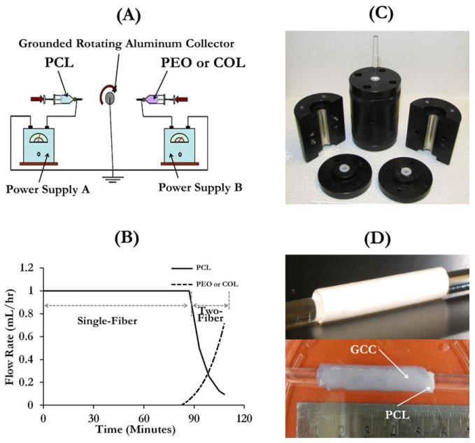
PCL was dissolved in a 5:3:2 mixture of dichloromethane, dimethylformamide, and methanol to obtain an 8% (wt) PCL solution. PEO powder was dissolved in acetonitrile to obtain the PEO solution (4.5%, wt). Collagen fibers were dissolved in the propanol solution to obtain the collagen solution (8.3%, wt). Single-polymer nanofibrous materials were fabricated by a single electrospinning apparatus, whereas materials with dual-polymer composition, such as PEO and PCL, were fabricated by a double-electrospinning apparatus [Figure 1(A)]. The PCL solution was stored in a 5-mL syringe which was connected to a blunt-ended needle that served as a spinneret charged by a high voltage power supply. The spinneret moved over an 18 cm path with a speed of 5 m/s along the collector mandrel which was under the control of a linear motorized stage. The cylindrical collector rotated at a constant velocity by a brushless rotating electric motor. The rotation speed to produce PCL fibers was set at 400 rpm. PCL fibers were collected with a needle–collector distance of 22 cm. The voltage and flow rate for collecting the PCL fiber were set to 27 kV and 1 mL/h, respectively. PCL was spun up to a thickness of 120 μm with or without surface modifications. To facilitate the detachment of scaffold materials from the collector and to protect the scaffold lumen surface, the collector was tightly wrapped with a thin aluminum foil with an ultrathin PEO layer covering its surface. The water-soluble PEO fibers were electrospun before PCL. After the production of the graft material, the material was soaked in deionized water to remove PEO, so that the tubular graft made of PCL fibers was released from the foil. For vascular implants, heparin, a thromboresistant molecule and endothelial attractant,32 was added to the PCL layer. This was done by dissolving heparin in the methanol to obtain a heparin–methanol solution (8%, wt) which was then used to prepare the mixture solvent for PCL, and the total heparin concentration in the resulting PCL solution was 0.5% by weight.
FIGURE 1.
Illustration of the graft fabrication process. (A) Illustration of the double-electrospinning apparatus used to spin PCL with PEO or collagen on a rotating aluminum collector, (B) the flow feed rate varies with the time for the production of a PCL scaffold with a 20-μm-thick interwoven fiber segment with PEO or collagen, (C) mold used to produce multilayer grafts, and (D) illustration of a one-layer PCL graft (top) and a multilayer graft (bottom). [Color figure can be viewed in the online issue, which is available at wileyonlinelibrary.com.]
To enhance the interface interaction and thus the layer adhesion, three surface modification strategies of PCL fibers were introduced: (a) creating high porosity (HP) at the surface, (b) forming double-spun (DC) collagen/PCL layer on the surface, and (c) using OP to activate the surface. The corresponding PCL scaffolds were referred to as PCL(HP), PCL(DC), and PCL(OP) hereafter. The production of PCL(HP) and PCL(DC) scaffolds were based on our previously established double-electrospinning technique.31 The double-electrospinning apparatus programed the sequential and simultaneous electrospinning processes of PCL and PEO or collagen on a rotating mandrel collector. The electrospun composite was characterized by varied compositions over the thickness. Briefly, a 100-μm-thick single-fiber segment (PCL fibers), and a 20-μm-thick two-fiber segment (interwoven fibers of PCL and PEO or collagen) were deposited in sequence on the grounded cylindrical aluminum collector. The fabrication of the two segments was a continuous spinning process, which structurally integrated the single-fiber segment with the two-fiber segment. During the fabrication of the two-fiber segment, the two spinnerets, which were placed on the opposite side of the rotating collector and perpendicularly oriented with respect to the principal axis of the collector, were moved in concert. The voltage and collector distance for collecting the PEO or collagen fibers were set to 30 kV and 18 cm, respectively. The feed rate of each solution varied independently via separate syringe pumps during the course of deposition. To generate the interwoven fiber network, the feed rates of PCL and PEO or collagen were programmed to vary with the time, according to Figure 1(B). To create PCL(HP) scaffolds, the PCL scaffolds with PCL/PEO surface were soaked for an hour in deionized water to eliminate the PEO component and solvent residuals, thus increasing the porosity on the surface. The PCL(DC) scaffolds were produced by first fabricating unmodified PCL scaffolds (120 μm), then removing them from the aluminum foil, and finally placing them in the vacuum chamber of an etcher at 0.2 Torr by applying OP for 5 min. The oxygen flow rate and the radio frequency power were set to 0.5 cm3/min and 5.0 W, respectively. It is known that OP activates PCL surfaces by introducing hydroxyl and carboxyl groups.33,34 As the reactive species were not stable, the treated materials were used immediately. All the PCL scaffolds were cut into tubes of a uniform length of about 30 mm for the formation of multilayer grafts.
Preparation of multilayer vascular grafts
Preparation of the gel for the outer sleeve was done by following the protocol we developed previously.30 Briefly, rat tail collagen (type I) in 0.02 N acetic acid (pH 4.0) at 9 mg/mL (BD Biosciences, San Jose, CA) was first transferred to a centrifuge tube on ice. Then, 1× Dulbecco’s phosphate-buffered saline (DPBS, Invitrogen Corporation, Carlsbad, CA) and 10 × Hank’s balanced salt solution containing phenol red was added to the solution, followed by the addition of chitosan suspension. Chitosan (molecular weight = 100,000–300,000 g/mol, 90% deacetylation, Milan Panic Biomedicals, Solon, OH) was dissolved in 1% acetic acid, resulting in a chitosan suspension of 10 mg/mL concentration with a viscosity of 2000–3000 mPa s. The pH of the pregel mixture was adjusted to 7.3 by the careful addition of 1 M NaOH. Finally, the mixture was topped off with 1× DPBS solution to the predetermined volume. The final concentrations of the collagen and chitosan in the collagen–chitosan constructs were 3 mg/mL and 3.5 mg/mL, respectively. The inner core manufactured with the electrospinning process was slid over a dry glass rod which was then fit in the vascular graft mold. The neutralized collagen–chitosan mixture was slowly poured into the graft mold [Figure 1(C)] around the PCL tube. To further remove bubbles which influence mechanical properties by introducing void defects in gel constructs, the pregel solution stayed on ice for 5 min before it was transferred into the incubator. Finally, the mold was transferred into an incubator to initiate gelation at 37°C. After 10 h of gelation, the outer sleeve was crosslinked with 1 mM or 2.5 mM genipin in 1× DPBS for 10 h. The crosslinker concentration was determined by our previous study,30 according to its effect on SMC activities. The samples were washed five times in 1× DPBS to remove genipin residues. For physical and mechanical characterizations, two types of single-layer PCL tubes without the outer GCC sleeve were used. They had thicknesses of 120 μm and 240 μm and were referred to as PCL (120 μm) and PCL (240 μm), respectively. The multilayer grafts using PCL(HP) for the inner core were referred to as PCL(HP)–GCC, those using PCL(DC) as PCL(DC)–GCC, and those using PCL(OP) as PCL(OP)–GCC. Figure 1(D) demonstrated a representative one-layer graft and a multilayer graft.
Structural characterizations
Graft sections, approximately 10 mm in length, were obtained from all the samples in hydrated and dehydrated conditions. The graft sections were frozen in liquid nitrogen at approximately −195°C, followed by drying in a critical-point drying chamber (Labconco, Kansas City, MO) for 48 h. For assessment of microscopical structure, the dried graft samples were embedded in a cryo-optimum cutting temperature compound (Andwin Scientific, Schaumburg, IL), and sectioned in a cryostat. These samples were sectioned transversely in parallel to the cross section. The resultant 15-μm-thick histological sections were placed on glass slides. The slides were then stained with Van Gieson method, and then observed under a light microscope (Zeiss Axiovert S100, Carl Zeiss, Germany) at 20× magnification. For ultrastructural evaluation, the frozen-dried graft samples were sputtered with gold and imaged under a field emission scanning electron microscope (FESEM, Zeiss Supra40, Carl Zeiss, Germany).
Fourier transform infrared spectroscopy analysis
The transverse cross sections of unmodified PCL, collagen, and PCL(DC) scaffolds were frozen in liquid nitrogen and then dried in a critical-point drying chamber for 48 h. The incorporation of collagen in the PCL fibrous matrix was evaluated using an attenuated total reflectance Fourier transform infrared (ATR–FTIR) spectrometer Nicolet 4700 (Thermo Fisher Scientific, Waltham, MA). Comparisons were made between samples using IGOR software (WaveMetrics, Tigard, OR) to identify the peaks and to calculate the areas under the peaks.
Physical and biomechanical characterizations of vascular grafts
The water permeability, burst strength, compliance, and suture retention strength of vascular grafts were determined according to the methods prescribed in the industrial standard—ANSI/AAMI/ISO 7198:1998/2001/(R) 2004 (Cardiovascular Implants: Tubular Vascular Prostheses).
Water permeability
Tube adapters were inserted onto both ends of the multilayer graft. Suture threads were used to secure the graft on the adapters. Then, the graft was cannulated by connecting one end of the graft to a water reservoir and closing the other end using a flow valve. Air, pressurized at 16 kPa (120 mmHg), was imposed onto the water column in the reservoir. Due to the pressure, water permeated through the graft. Once the flow became steady, the permeate fluid was collected in a beaker and the water volume collected in 1 min was measured. The graft permeability (units: mL/cm2/min−1) was determined using the equation:
where τ is the graft permeability, Q is the fluid volume passing through the graft, and A is the cross-sectional area of the aperture in the sample holder.
Burst strength
To perform burst strength tests on hydrated grafts, a thin latex tube was slid into the lumen of the tubular graft and the tube adapters were inserted on both ends. Suture threads were used to secure the graft on to the latex tube near the adapters. Then, the tubular graft was cannulated with CO2 being pumped in through one end of the graft, using teflon tubing, while closing the other end using a flow valve. Due to the increase of CO2 flow in to the latex tube, the latex tube expanded causing the vascular graft outside to expand. The expansion was allowed until graft failure occurred. The pressure at which this failure of the vascular graft occurred was recorded as burst strength or burst pressure of the graft.
Compliance
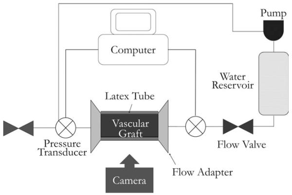
For compliance tests, the tubular graft was cannulated with the latex tube inserted in a way similar to the burst strength test. The graft was then loaded onto a custom-made fixture and connected to a flow network via pressure gauges (Living Systems Instrumentation, Burlington, VT) on both ends of the graft (Figure 2). The pressure in the graft was controlled using varying speed of a water pump, to obtain a steady pressure from 0 mmHg to 160 mmHg, with an increment of 10 mmHg. At each pressure, images of the graft dilatation were taken using a Canon EOS 450D camera (Canon, Tokyo, Japan). These images were analyzed using a customized script in Matlab® (MathWorks, Natick, MA) to obtain the graft diameter at each pressure point. Then, the compliance of the graft (% per 100 mmHg) was determined with the following equation:
where R is the radius of the graft at pressure P.
FIGURE 2.
Schematic illustration of the system setup for vascular graft compliance test.
Suture retention strength
To determine the suture retention strength, the vascular graft was cut normal to the long axis into small rectangular strips with a dimension of 10 mm × 5 mm. A suture was inserted 2 mm from the end of the stretched strip of the graft through the graft wall to form a half loop and the other end of the graft was attached to the lower end of the MTS Insight electromechanical testing system (MTS Systems Corp., Eden Prairie, MN). The other end of the suture was attached to a 2000 N load cell (MTS Systems Corp). The suture was pulled at the rate of 150 mm/min. The force required to pull the suture through the graft or to rupture the graft wall was recorded as suture retention. In this study, the suture retention strengths of PCL (120 μm) and PCL(HP)–GCC were studied.
Characterizations with vascular cells in vitro
Pulmonary artery ECs and SMCs with passages 4–8 were used in the in vitro cell characterizations. The cell culture was maintained in the Dulbecco’s modified eagle medium containing 10% fetal bovine serum and 1% penicillin–streptomycin. PCL(HP)–GCC grafts were used for cell characterization. Before cell seeding, the multilayer vascular grafts were frozen in liquid nitrogen and dried in a critical-point drying chamber. Then, the multilayer graft, suture strings and adapters were sterilized in 100% ethanol for 1 h. All jackets and plugs used in the seeding process were auto-claved for 20 min. The vascular grafts were then rehydrated by soaking into sterile 1× DPBS and then medium with FBS. The centrifuge method was used to seed ECs onto the surface of the graft lumen, using modified protocols reported previously.35,36 This was started by securing one end of the graft with an adapter plug with sutures. Then, the suspension of freshly detached EC cells with a density of 1 × 10⁶ cells/mL was obtained. After filling the space in the graft lumen with the EC suspension, the other end of the graft was secured with an adapter plug. Custom-made jacket rings were then wrapped around the graft to fit it into a centrifuge tube and adapter spacer rinds were placed around both adapters. The fully assembled centrifuge tube was then placed in the center of a centrifuge. The tube was aligned perfectly to the center to avoid any wobbling or uneven spinning. Then, the system was allowed to spin at 2000 rpm for 5 min. After centrifuge seeding, the graft secured with the adapters was allowed to sit for about an hour before carefully removing the adapters. After seeding ECs in the lumen, pulmonary artery SMCs were seeded into the outer sleeve of the grafts. The SMC suspension was prepared in the similar medium and with the same cell density as ECs. The liquid on the outer sleeve of the grafts was removed by gently and quickly rolling the graft on cotton gauze. The SMC suspension (1 mL) was then allowed to be absorbed to the outer sleeve layer. Finally, the tube containing the graft seeded with ECs and SMCs was incubated for about an hour. The graft was transferred into a centrifuge tube filled with fresh medium, which was put onto a tube rotator rotating at a constant speed of 8 rpm. The tube cap was slightly untightened to allow diffusion of oxygen. The rotator was placed inside a cell culture incubator set at 37°C and 5% CO2. Graft samples were collected after culture for 1 h, 3 days, and 6 days, respectively. Samples were fixed in 3.7% formaldehyde, stained with DAPI, and then observed under a fluorescent microscope at 20× magnification. Samples were also embedded in cryostat embedding medium (Tissue Tek, Torrence, CA) and sectioned with a cryostat at −20°C. Histological sections were stained with hematoxylin and eosin, and observed under a light microscope at 20× magnification. Additionally, samples were cut transversely to obtain the cross section for en face imaging of EC morphology on the graft lumen under a FESEM.
Heparin release test
Heparin-impregnated PCL scaffolds were cut into small pieces (25 mm × 5 mm × 0.15 mm, approximate weight of 60 mg). Each one was soaked in 5 mL of DPBS at 37°C, under constant mild shaking on a shaker table. After 12 h and 1, 4, 7, 10, 13, 16, 23, and 30 days, 150 μL were extracted to measure the heparin content and replaced with fresh DPBS. The Biophen heparin Anti-Xa Assay/Detection Kit (Hyphen BioMed, Mason, OH) was used to detect the amount of heparin released at each time point. Heparin Anti-Xa method is a two-stage chromogenic assay capable of measuring the Anti-Xa activity of homogeneous heparin in plasma or in purified solutions. The average release values over four samples, and the standard deviation at each time point were obtained.
Implant evaluation in rabbits
Four New Zealand white rabbits were premedicated with subcutaneous injections of medetomidin (210 mcg/kg), midazolam (0.5 mg/kg), and morphine (1 mg/kg). An intravenous catheter was placed in a vein of the ear and propofol (5–8 mg/kg) was used to induce anesthesia. After intubation, anesthesia was maintained with Isoflurane in 100% oxygen. At the time of induction, rabbits receive enrofloxacin at a dose of 5 mg/kg. The rabbits were placed on dorsal recumbency. The abdomen was clipped with a #40 blade and prepared with chlorhexidine for surgery. After draping the abdomen with sterile surgical drape, a midline incision was performed. The colon was retracted medially, and the infrarenal aorta was exposed. They were ligated with 5-0 polypropylene suture. Heparin was administered at the dose of 200 U/kg intravenously. After dissection of the infrarenal aorta over 2 cm, vascular clamps were applied to isolate the infrarenal aorta. The aorta was transected between the clamps. An acellular PCL(HP)–GCC graft with a 3 mm inner diameter was anastomosed in an end-to-end fashion with two continuous 7-0 polypropylene sutures. After completion of the anastomosis, the clamps were removed and the anastomosis inspected for leakage and patency. The abdominal incision was then closed in a routine fashion. The animals received buprenorphine (0.05 mg/kg) and meloxicam (0.3 mg/kg) after the surgery. Before explant, ultrasound images of the grafts, the upstream and downstream neighboring artery, were taken to visualize thrombus formation or narrowing of the graft. After 1 day, the graft as well as the distal and proximal aortal sections were explanted and fixed in 10% formaldehyde, cryosectioned and stained with hematoxylin and eosin. These stained sections were observed under the light microscope at 20× magnification.
Data analysis and statistics
Data were statistically analyzed using the one-way analysis of variance test. Student’s t test was then used to compare the means of each individual group. The level of significance was set at a α = 0.05 for 95% statistical significance. Error bars on all the histogram charts represent the standard error of the mean based on the total number of the samples.
RESULTS
Structure and interface characterization
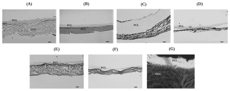
The histological sections of various multilayer grafts were observed under an optical microscope, which clearly demonstrated the adhesion between the inner core and the outer sleeve of grafts under dehydrated and hydrated conditions (Figure 3). The histological results showed that consistency of adhesion was dependent on the method of surface modification. The multilayer adhesion in PCL(OP)–GCC and PCL(HP)–GCC was more stable than PCL(DC)–GCC. It was also clear that hydration plays an important role in the graft integrity. Because PCL was hydrophobic and GCC was hydrophilic, the thickness of PCL layer in PCL(OP)–GCC and PCL(HP)–GCC did not significantly alter during the hydration or dehydration processes, whereas the thicknesses of the GCC layers in all the conditions significantly reduced in the dehydrated state compared with the hydrated state. However, by adding hydrophilic collagen component and double-electrospinning it with PCL in the two-fiber segment, the thickness of the electrospun layer of PCL(DC)–GCC significantly increased after hydration and was around four times thicker when compared with the electrospun layer of PCL(OP)–GCC or PCL(HP)–GCC. This could be attributed to the water absorption capability of collagen fibers. In addition, it was found that the thickness of GCC gels significantly reduced during the gel formation and crosslinking processes, and it further shrunk when the multilayer graft was subjected to freeze-dry dehydration. Therefore, the thickness of GCC gels appeared only about a quarter of the original mold that held the prepolymer solution. Additionally, it was found that the structure and final thickness of the outer graft sleeve slightly varied with the interface design. Using a dark-field setting, the microstructural differences of the two layers were further demonstrated [Figure 3(G)]: the electrospun layer was characterized by a highly dense structure, whereas the GCC layer was more porous.
FIGURE 3.
Optical microscopy images showing the histological microstructure of representative hydrated and dehydrated multilayer samples. (A) Hydrated PCL(HP)–GCC, (B) dehydrated PCL(HP)–GCC, (C) hydrated PCL(DC)–GCC, (D) dehydrated PCL(DC)–GCC, (E) hydrated PCL(OP)–GCC, (F) dehydrated PCL(OP)–GCC, and (G) dark-field image of a hydrated PCL(HP)–GCC. Scale bar: 100 μm.
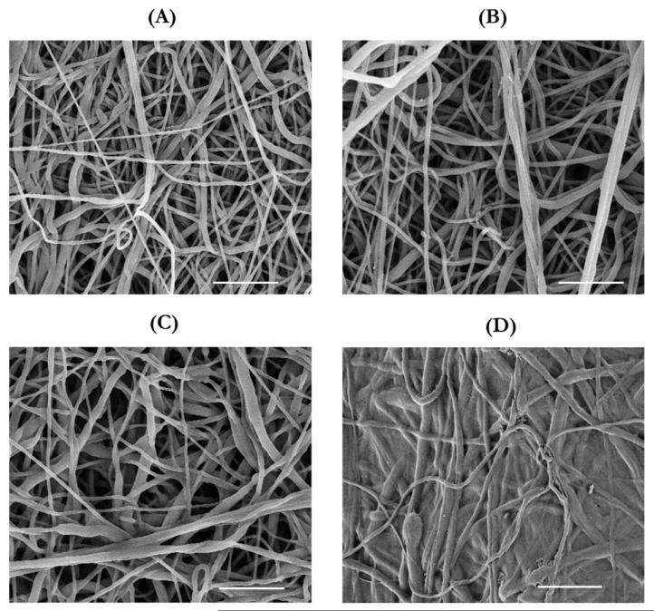
The influences of surface modifications on the structure of the PCL inner core were examined using FESEM (Figure 4). The unmodified PCL surface exhibited a porous network of fibers [Figure 4(A)]. Compared with the unmodified PCL surface, the surface of PCL(HP) showed larger pores and increased porosity [Figure 4(B)]. Using an imaging analysis tool (NIH Image J), we found that the porosity increased from 46% to 53%, but this result largely underestimated the increase in three-dimensional (3D) porosity of PCL(HP), because these images only scanned 2D surface and displayed fibers underneath through the pores. As for the surface of PCL(DC), it was difficult to distinguish between electrospun collagen and PCL fibers in the FESEM images, because they were similar in the structure [Figure 4(C)]. Thus, the collagen component was confirmed by FTIR spectroscopy analysis on the PCL(DC) samples. As for the surface of PCL(OP), the FESEM micrograph showed that the OP-treated PCL fibers on the surface partly melted away and filled the pores, resulting in reduced pore size and porosity [Figure 4(D)].
FIGURE 4.
FESEM images of the electrospun surfaces as the graft interfaces. (A) PCL without any surface modifications, (B) PCL(HP), obtained by electrospinning PCL with PEO which was then removed by dissolution in DI H2O, (C) PCL(DC), obtained by electrospinning PCL with collagen, and (D) PCL(OP), which has been treated with oxygen plasma. Scale bar: 10 μm.
FTIR–ATR characterization results showing the incorporation of electrospun collagen fibers in the electrospun PCL matrix
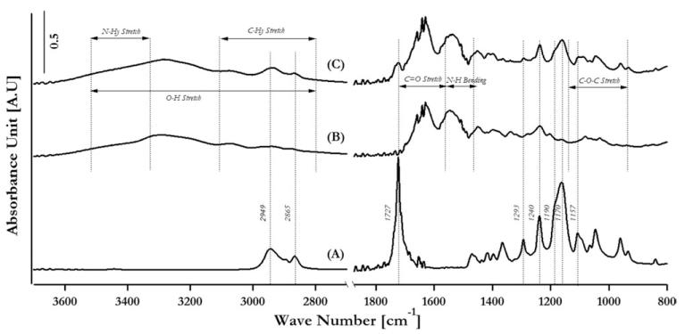
Figure 5 demonstrated the spectra of PCL (curve A), collagen (curve B), and PCL electrospun with collagen (curve C), showing the incorporation of component additives in the double-electrospun samples. The assignments of peaks that are common to PCL, collagen, and PCL(DC) are presented in Table I. For the spectra of collagen and PCL(DC), typical peaks were derived from amide I (C=O stretching at 1630 cm−1), amide II (N—H bending at 1550 cm−1), and the mixed stretching and bending vibrations of the C—O—C bond at 1150–970 cm−1. For the spectra of PCL and PCL(DC), the typical peaks were derived from asymmetric CH2 stretching (2949 cm−1), symmetric CH2 stretching (2865 cm−1), C=O stretching (1727 cm−1), C—O and C—C stretching in the crystalline phase (1293 cm−1), asymmetric COC stretching (1240 cm−1), OC—O stretching (1190 cm−1), symmetric COC stretching (1170 cm−1), and C—O and C—C stretching in the amorphous phase (1157 cm−1). Therefore, the characteristic collagen peaks and the characteristic PCL peaks in the crystalline and amorphous phases were present in the FTIR spectra of the PCL(DC) fiber matrices, confirming the efficacy of the surface modification.
FIGURE 5.
Fourier transform infrared spectroscopy analysis of (A) PCL, (B) collagen, and (C) PCL double electrospun with collagen.
TABLE 1. Peak Assignment for FTIR Spectra.
| Position (cm−1) | PCL |
|---|---|
| 2949 | Asymmetric CH2 stretching |
| 2865 | Symmetric CH2 stretching |
| 1727 | C=O stretching |
| 1293 | C—O and C—C stretching in the crystalline phase |
| 1240 | Asymmetric COC stretching |
| 1190 | OC—O stretching |
| 1170 | Symmetric COC Stretching |
| 1157 | C—O and C—C stretching in the amorphous phase |
| Position (cm−1) | Collagen |
| 3500–2800 | O—H stretching |
| 3500–3450 | N—Hy stretching |
| 3100–2800 | C—Hy stretching |
| 1790–1580 | C=O stretching |
| 1580–1470 | N—H bending |
| 1150–940 | C—O—C Stretching |
Physical and biomechanical characterizations of multilayer grafts
Physical and biomechanical properties of vascular grafts play critical roles in graft functions in vivo, and thus are included in the FDA standards. Herein, we determined several essential graft properties, including permeability, burst strength, compliance and suture strength, and studied the effects of graft structure designs on these properties.
Water permeability
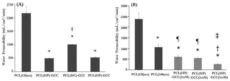
Results from water permeability tests showed that the mean permeability value of 120-μm-thick, single-layer PCL grafts without an outer sleeve was 2380 mL/cm2/min [Figure 6(A)]. With the addition of an outer sleeve using various surface modification strategies on the PCL inner core (120 μm), the mean water permeability values were found to be 528 mL/cm2/min, 1112 mL/cm2/min, and 553 mL/cm2/min for the PCL(HP)–GCC, PCL(DC)–GCC, and PCL(OP)–GCC grafts, respectively. The water permeability values of PCL(HP)–GCC and PCL(OP)–GCC were reduced four times, when compared with the PCL (120 μm) samples. The water permeability value of PCL(DC)–GCC samples was significantly higher than PCL(HP)–GCC and PCL(OP)–GCC and was reduced about two times when compared with the PCL (120 μm) samples. In addition, to study the influence of each layer on water permeability, we, respectively, varied the design parameters of the PCL layer and the GCC layer, which was the thickness of the inner core and the crosslinking condition of the outer sleeve [Figure 6(B)]. Results showed that the mean permeability value of the 240-μm-thick, single-layer PCL grafts was 1030 mL/cm2/min. There was a significant decrease in the mean permeability value with the increase in PCL thickness: about two times reduction of permeability with two times increase in the PCL thickness. We also found that the permeability value for the grafts with more crosslinked sleeve using 10 mM of genipin,30 was reduced two times (264 mL/cm2/min), when compared with the multilayer grafts with less crosslinked sleeve using 1 mM (609 mL/cm2/min) or 2.5 mM (528 mL/cm2/min) of genipin. This might be due to the reduced flexibility of the pores in more crosslinked sleeve to slow down the water movement under pressure. Thus, the results here demonstrated that engineering the integration of the multilayer structure, in addition to the individual layer designs such as electrospun PCL thickness and GCC crosslinking density significantly influenced the water permeability values of the vascular grafts.
FIGURE 6.
Effects of the layer interface, the electrospun layer thickness and the crosslinking condition of the GCC layer on the graft water permeability. (A) The single-layer PCL graft showed significantly higher permeability than the multilayer grafts with various interface. (B) Graft permeability varied with the thickness of PCL inner core (black bars) or the crosslinking condition of outer sleeve (gray bars). *: p < 0.05 w.r.t. PCL (120 μm), ‡: p < 0.05 w.r.t. PCL(HP)–GCC (2.5 mM), and ¶: p < 0.05 w.r.t. PCL (240 μm).
Burst strength
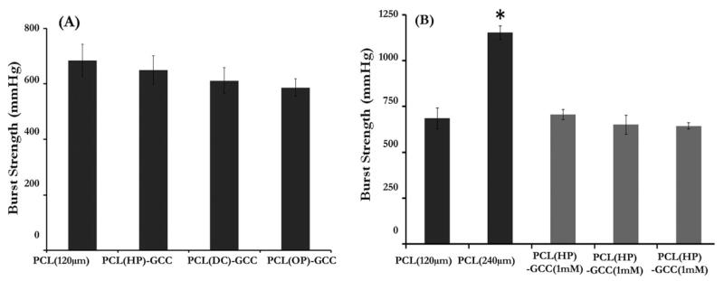
Results from burst strength tests showed that the mean burst strength values of PCL scaffolds [Figure 7(A)] without an outer sleeve were 684 mmHg and 1172 mmHg, respectively, for the 120-μm- and 240-μm-thick, single-layer samples. The burst strength was significantly improved by increasing the electrospun PCL thickness. The burst strength values of the multilayer grafts with different interfaces, PCL(HP)–+GCC, PCL(DC)–GCC, and PCL(OP)–GCC, were found to be 695, 638, and 611 mmHg, respectively. No significant differences in burst strength were found among these three multilayer grafts or between any multilayer graft and single layer graft with the same PCL thickness (120 μm). Additionally, there were no significant differences in burst strength between the multilayer grafts with differently crosslinked outer sleeves [Figure 7(B)].
FIGURE 7.
Effects of the layer interface, the electrospun layer thickness and the GCC layer crosslinking condition on the graft burst strength. (A) Burst strength of single-layer PCL grafts and multilayer grafts with various interfaces; (B) burst strength of grafts with varied thickness of the PCL inner core (black bars) or varied crosslinking condition of outer shell (gray bars). *: p < 0.05, w.r.t. PCL (120 μm).
Compliance
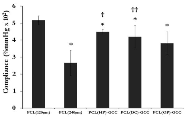
Results from compliance tests using cannulation pressures in the range of 80–120 mmHg showed that PCL (120 μm) had an average compliance of 5.3%, whereas the multilayer grafts, PCL(HP)–GCC, PCL(DC)–GCC, and PCL(OP)–GCC possessed average compliance values of 4.5%, 4.2%, and 3.8%, respectively (Figure 8). PCL (240 μm) exhibited a much lower compliance of 2.7%. The compliance of unmodified PCL (120 μm) single-layer samples was significantly higher than that of PCL (240 μm).
FIGURE 8.
Effects of the layer interface and the electrospun layer thickness on the graft compliance (%/100 mmHg) of single-layer PCL grafts and multilayer grafts with various interfaces. *: p < 0.05 w.r.t. PCL (120 μm), †: p < 0.05 w.r.t. PCL (240 μm), and ††: p < 0.1 w.r.t. PCL (240 μm).
Suture strength
The suture retention strength of PCL (120 μm) and PCL(HP)–GCC was found to be 2.05 N and 2.38 N, respectively, with no significant difference between them. These values were comparable to the previously reported values of other PCL-based synthetic grafts,37 although it was lower than saphenous vein (approximately 4 N) and PTFE graft (4.9–6.7 N).
EC and SMC activities on graft in vitro
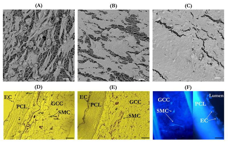
Results from characterization of cell-seeded grafts have demonstrated that the multilayer graft supported vascular cell cocultures and cell growth to form engineered blood vessel in vitro. The successful seeding and culture of both ECs and SMCs in their respective layers of the multilayer scaffold was shown in Figure 9. The en-face FESEM micrographs clearly demonstrated that compared to the initial cell density [Figure 9(A)], the cell density after 3 days increased, forming a more confluent layer of ECs due to cell proliferation [Figure 9(B)]. Further cell proliferation and higher level of cell confluency were found after 6 days of cell seeding [Figure 9(C)]. Optical images of histological sections stained with hematoxylin and eosin also demonstrated a similar EC proliferation pattern in the lumen by showing the cross section of the cell-seeded grafts [Figure 9(D,E)]. In addition, these images showed that the rotational culture maintained SMCs in the GCC outer sleeve of the graft. The fluorescent imaging using DAPI also illustrated the co-culture of EC and SMC in the different layers of the grafts [Figure 9(F)].
FIGURE 9.
Microscopic examinations of cell-seeded grafts. (A–C) FESEM images of EC-seeded graft lumen after 1 h (A), 3 days (B), and 6 days (C) of cell seeding. (D and E) Optical microscopy images of the transversal cross section of cell-seeded grafts after 1 h (D) and 6 days (E) of cell seeding. (F) Fluorescent microscopy image of DAPI-stained cells after 3 days of cell seeding. Scale bar for A–C: 20 μm and for D–F: 100 μm. [Color figure can be viewed in the online issue, which is available at wileyonlinelibrary.com.]
Sustained heparin release from the graft
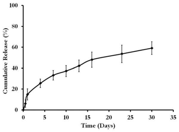
Figure 10 shows the characterization of heparin, which demonstrates the incorporation and gradual release of the active molecule. The cumulative release curve of heparin shows that heparin encapsulated PCL can be released over the time in days. Within the first 24 h, 14.88 ± 5.31% had been released and after 30 days a total of 59.16 ± 6.12% heparin was released.
FIGURE 10.
Release of heparin from the PCL construct.
Short-term implantation showing in vivo biocompatibility of the graft
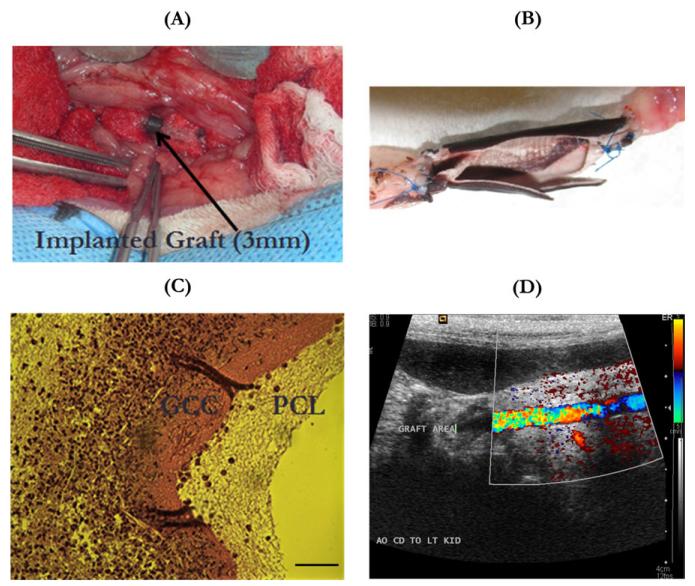
Acellular grafts were used in the in vivo biocompatibility evaluation of vascular grafts. Figure 11(A) showed that a 3-mm diameter, multilayer vascular graft was used to replace the abdominal aorta in a rabbit with anastomosis covered by medical-use gauzes. Explanted vascular grafts revealed a clean lumen with no blood clots or platelet adhesions [Figure 11(B)]. There were no unfavorable inflammatory or thrombogenic reactions produced by the grafts in all the tested animals. The sectioned and stained explanted graft showed cell invasion at the site of anastomosis [Figure 11(C)]. These cells preferred to invade the GCC layer rather than the PCL layer. These cells were likely adventitial fibroblasts or SMCs migrating from the surrounding tissues. Ultrasonic evaluation of the postimplantation blood flow through the graft revealed reperfusion of the grafts with pulsatile blood flow [Figure 11(D)].
FIGURE 11.
Biocompatibility evaluation of vascular grafts in vivo with a rabbit model. (A) A 3-mm-diameter multilayer vascular graft replaced the abdominal aorta of a rabbit with anastomosis covered with medical-use gauze; (B) the open-lumen view of an explanted multilayer vascular graft with neighboring arteries, showing no thrombosis or occlusion in the graft lumen; (C) optical image of the histological cross-sectional slice of an explanted graft stained with hematoxylin and eosin, showing the migration of cells from surrounding tissues mainly into the GCC layer rather than the PCL layer, scale bar:100 μm; (D) ultrasonic image showing blood reperfusion through the graft and the lumen without any thrombosis or stenosis. [Color figure can be viewed in the online issue, which is available at wileyonlinelibrary.com.]
DISCUSSION
This study reported the development and characterization of robust, compliant multilayer constructs for vascular graft applications. The developed grafts were made up of a densely packed fibrous PCL membrane and a porous GCC gel, to, respectively, provide the matrix environments for cells in the vascular intima and media. To prevent delamination and to integrate the layers with drastically different structures and physicochemical characteristics for their additive properties to achieve enhanced graft function under the physiological flow pressure, various interfacial designs were examined. Results showed that the PCL(HP)–GCC graft with increased porosity at the interface provided the layer adhesion for successful construct integration and offered desired graft permeability, implant strength, and high compliance (4.5%) for graft implants. Biocompatibility tests further demonstrated that the multilayer construct supported coculture and growth of distinct vascular cells in vitro and were readily implanted to replace artery in vivo allowing cell ingrowth and flow reperfusion.
The formation of a multilayer graft through combining two biomaterials with drastically different properties to achieve additive or improved graft properties, that is, permeability, compliance, and burst strength, compared with the single component material, remains a challenging task. The multilayer grafts presented here were made from physicochemically different materials: PCL is highly hydrophobic, stiff, and strong, whereas GCC is highly hydrophilic, elastic, and mechanically weaker. Without any surface modifications, GCC easily slipped over the PCL surface. Herein, the adhesion between the two layers was designed using a physical or a chemical attachment process. The physical process involved entanglement of collagen–chitosan gels in the large pores of PCL fibers near the interface between the two materials. During the outer sleeve formation, the collagen–chitosan pregel mixture could more readily enter larger pores, and form a fiber-sheet structure during the gelation to physically entangle with PCL fibers. Small pores may inhibit the gel structure formation. Under the physiological stresses as used during compliance and burst strength tests, the multilayer constructs maintained the integral structure. The chemical attachment process involved the formation of the covalent chemical bonds between the electrospun layer and the GCC layer. This was achieved by two methods. PCL(DC) had electrospun collagen on the surface, which could be crosslinked with the collagen–chitosan hydrogel in the GCC outer sleeve.29 However, this method resulted in excessive shrinkage or expansion of the inner layer during hydration and dehydration process, which could introduce separation and cracking leading to suboptimal layer adhesion. The method involving OP treatment of an unmodified pure PCL tube introduced new reactive oxygen groups on the surface of the PCL fibers, thereby forming a stable bond between the two layers.33,34 But the major issue in this process was to identify an appropriate amount of RF power and flow rate for OP, which was limited to 5.0 W and 0.1 cm3/min, respectively. This limit was mainly due to the melting of the inner core at higher RF powers and flow rates, even though higher powers were used in other studies.33,34 Even under the low power and flow rate, the FESEM image showed melted PCL fibers that filled the pores.
Water permeability is one critical parameter used in the assessment of graft function; our multilayer grafts provide a solution to meet the functional requirement for graft permeability. Values above 800 mL/cm2/min are generally considered high and preclotting must be applied before implantation, whereas permeability below 600 mL/cm2/min does not require preclotting, but grafts with lower permeability in that range have been shown to heal more slowly because of the limited molecule transport.38,39 By virtue of being a nanofibrous material with connected pores, a thin PCL layer (120 μm) allows large quantities of water to permeate under the physiological flow pressure. Yet with the addition of an outer sleeve with a low crosslinking density, the permeability was reduced considerably, around two to four times. The permeability of multilayer grafts with strong layer adhesion fell in the ideal range of 500–600 mL/cm2/min for immediate grafting and fast healing. Results showed that the graft permeability was dependent on the crosslinking condition of GCC and the layer adhesion, which further demonstrated the importance of the hydrogel sleeve to the reduction of graft permeability. PCL(DC)–GCC did not form as good adhesion as PCL(HP)–GCC and PCL(OP)–GCC at the interface [Figure 3(B,C)], and thereby the permeability of PCL(DC)–GCC was significantly higher than that of PCL(HP)–GCC and PCL(OP)–GCC [Figure 6(A)]. With good layer adhesion to maintain structural integrity under flow, the GCC layer forms an effective barrier to reduce permeability. The reduction in the permeation can be attributed to the decrease in the permeability constant as well as the increase in the graft thickness. Darcy’s law of diffusion states that the permeability of a porous membrane is directly proportional to the pressure gradient across the membrane and inversely proportional to the membrane thickness. The equation of the relationship is:
where q is the amount of water permeated through unit area in unit time, KD is the permeability constant, ΔP is the pressure change, and t is the membrane thickness. With the addition of the GCC layer, not only the thickness “t” increases, but also the pressure gradient across the graft decreases because the hydrophilic GCC matrix has sites for binding of water molecules, thereby reducing the mass transfer across the graft.
In addition to permeability, both compliance and burst strength are important determinants to graft functioning in vivo, but achieving the balance between them as shown by native arteries is a long-standing issue.27,40 Herein, the multilayer graft combines two types of materials: PCL, a strong yet stiff material31 and GCC, a weaker and more elastic scaffold.30 The PCL inner core determines both burst strength and compliance of the multilayer graft, whereas the GCC layer is important to reduce permeability and keep grafts deformable under physiological pressure. Different from the permeability, the burst strength is mainly dependent on the PCL layer modification rather than GCC condition. The multilayer grafts thus possess adequate permeability and burst pressure (five times the higher end of physiological pressure), for immediately implantation. Furthermore, due to a thin PCL inner core, the compliance value of PCL(HP)–GCC (4.5%) is comparable to those of native vessels such as saphenous vein (4.5%) and umbilical vein (3.7%), and much higher than those of synthetic PTFE and Dacron grafts (1.6–2%) or crosslinked bovine xenografts (2.6%).22,41,42 Compared with PCL(HP)–GCC, the compliance of PCL(OP)–GCC is lower. This can be attributed to the changes of PCL fibers during OP treatment. The PCL-based grafts used in previous studies were characterized by much higher thicknesses, resulting in higher burst strength and lower compliance.17,18,37,43 Compliance plays an essen-tial role in cell activity and graft healing, due to its influence on hemodynamics at the site of anastomosis.22,23 Salacinski et al.22 demonstrated a nearly linear relationship between the graft compliance and the 1-month graft patency based on a number of in vivo studies. Using this patency–compliance relationship, we could expect that the 1-month patency rate of our grafts would be over 75%. The burst strength of our grafts, although lower than PTFE, is adequate for in vivo functioning. One key reason why the burst strength is lower than previously reported values for PCL fiber grafts is the difference in the PCL layer thickness, a major determinant to strength as demonstrated in the study.17 Nevertheless, the in vivo evaluation demonstrated the graft robustness for the use as artery implants. The short-term studies with rabbit models showed that there were no unfavorable thrombotic or inflammatory reactions. We also found that cells preferentially invaded into the GCC layer rather than the PCL layer [Figure 10(C)]; immune cells were not recruited to the lumen as the cells were stained negative with monocyte markers. This may be due to the larger pores and lower elastic modulus of the GCC layer in comparison to the PCL layer. Therefore, in addition to the complementary function in physical and mechanical properties, the two-layer design also provided layered structure for cell seeding or ingrowth in vitro and in vivo. However, long-term functional studies will need to be performed to further assess the effects of grafts on dynamic cell and tissue remodeling. Additionally, molecular environments mimicking those in the native blood vessels should be designed and incorporated into the structure-mimic vascular grafts demonstrated here. In summary, the multilayer constructs using techniques to structurally and functionally integrate two physicochemically different layers provide both mechanical properties and cellular and molecular environments for grafting applications.
CONCLUSIONS
This article reports the design and characterization of multilayer vascular grafts that are synthesized with a combination of electrospun PCL fibers and collagen-based scaffolds. We have identified the material interface as an important determinant to the graft integrity and property. Results have shown PCL as graft inner core mainly contributes to the biomechanical properties such as burst strength, compliance and suture strength, whereas GCC as the graft sleeve reduces the water permeability. Additionally, the PCL core and the GCC sleeve, respectively, provide the formation of EC monolayer and the cell ingrowth or 3D culture of SMCs. When implanted into rabbits, the graft did not elicit any unfavorable inflammatory or thrombogenic reactions in the short-term run.
ACKNOWLEDGMENTS
The authors thank Reuben Dodson and Winston Elliot for assistance with mechanical testing, Jerry Vadakel for assistance with electrospinning, and Dr. Antonella Motta for her assistance with FESEM imaging. The research is partly funded by NIH (NHLBI 097246-01 to W.T) and State of Colorado (Biodis-covery Program to W.T.).
Contract grant sponsor: NIH (NHLBI 097246-01 to W.T.)
Contract grant sponsor: State of Colorado (Biodiscovery Program to W.T.)
REFERENCES
- 1.Davies AH, Magee TR, Baird RN, Sheffield E, Horrocks M. Pre-bypass morphological changes in vein grafts. Eur J Vasc Surg. 1993;7:642–647. doi: 10.1016/s0950-821x(05)80710-8. [DOI] [PubMed] [Google Scholar]
- 2.Hofstra L, Bergmans DCJJ, Hoeks APG, Tordoir JHM, Kitslaar PJEHM. Assessment of inhomogeneities in elastic properties of in situ and reversed saphenous vein grafts in humans. Eur J Vasc Surg. 1994;8:670–676. doi: 10.1016/s0950-821x(05)80645-0. [DOI] [PubMed] [Google Scholar]
- 3.Davies MG, Hagen P-O. Pathophysiology of vein graft failure: A review. Eur J Vasc Endovasc Surg. 1995;9:7–18. doi: 10.1016/s1078-5884(05)80218-7. [DOI] [PubMed] [Google Scholar]
- 4.Porter KE, Varty K, Jones L, Bell PRF, London NJM. Human saphenous vein organ culture: A useful model of intimal hyperplasia? Eur J Vasc Endovasc Surg. 1996;11:48–58. doi: 10.1016/s1078-5884(96)80134-1. [DOI] [PubMed] [Google Scholar]
- 5.Baim DS. Percutaneous treatment of saphenous vein graft disease: The ongoing challenge. J Am Coll Cardiol. 2003;42:1370–1372. doi: 10.1016/s0735-1097(03)01039-8. [DOI] [PubMed] [Google Scholar]
- 6.Venkatraman S, Boey F, Lao LL. Implanted cardiovascular polymers: Natural, synthetic and bio-inspired. Prog Polym Sci. 2008;33:853–874. [Google Scholar]
- 7.Greenwald SE, Berry CL. Improving vascular grafts: The importance of mechanical and haemodynamic properties. J Pathol. 2000;190:292–299. doi: 10.1002/(SICI)1096-9896(200002)190:3<292::AID-PATH528>3.0.CO;2-S. [DOI] [PubMed] [Google Scholar]
- 8.Tiwari A, Salacinski HJ, Hamilton G, Seifalian AM. Tissue engineering of vascular bypass grafts: Role of endothelial cell extraction. Eur J Vasc Endovasc Surg. 2001;21:193–201. doi: 10.1053/ejvs.2001.1316. [DOI] [PubMed] [Google Scholar]
- 9.Klinkert P, Post PN, Breslau PJ, van Bockel JH. Saphenous vein versus PTFE for above-knee femoropopliteal bypass. A review of the literature. Eur J Vasc Endovasc Surg. 2004;27:357–362. doi: 10.1016/j.ejvs.2003.12.027. [DOI] [PubMed] [Google Scholar]
- 10.Kannan RY, Salacinski HJ, Butler PE, Hamilton G, Seifalian AM. Current status of prosthetic bypass grafts: A review. J Biomed Mater Res Part B: Appl Biomater. 2005;74B:570–581. doi: 10.1002/jbm.b.30247. [DOI] [PubMed] [Google Scholar]
- 11.L’Heureux N, Dusserre N, Marini A, Garrido S, de la Fuente L, McAllister T. Technology Insight: The evolution of tissue-engineered vascular grafts from research to clinical practice. Nat Clin Pract Cardiovasc Med. 2007;4:389–395. doi: 10.1038/ncpcardio0930. [DOI] [PubMed] [Google Scholar]
- 12.L’Heureux N, Paquet S, Labbe R, Germain L, Auger FA. A completely biological tissue-engineered human blood vessel. FASEB J. 1998;12:47–56. doi: 10.1096/fasebj.12.1.47. [DOI] [PubMed] [Google Scholar]
- 13.Niklason LE, Gao J, Abbott WM, Hirschi KK, Houser S, Marini R, Langer R. Functional arteries grown in vitro. Science. 1999;284:489–493. doi: 10.1126/science.284.5413.489. [DOI] [PubMed] [Google Scholar]
- 14.Berglund JD, Mohseni MM, Nerem RM, Sambanis A. A biological hybrid model for collagen-based tissue engineered vascular constructs. Biomaterials. 2003;24:1241–1254. doi: 10.1016/s0142-9612(02)00506-9. [DOI] [PubMed] [Google Scholar]
- 15.Engbers-Buijtenhuijs P, Buttafoco L, Poot AA, Dijkstra PJ, de Vos RAI, Sterk LMT, Geelkerken RH, Vermes I, Feijen J. Biological characterisation of vascular grafts cultured in a bioreactor. Biomaterials. 2006;27:2390–2397. doi: 10.1016/j.biomaterials.2005.10.016. [DOI] [PubMed] [Google Scholar]
- 16.L’Heureux N, Dusserre N, Konig G, Victor B, Keire P, Wight TN, Chronos NAF, Kyles AE, Gregory CR, Hoyt G, Robbins RC, McAllister TN. Human tissue-engineered blood vessels for adult arterial revascularization. Nat Med. 2006;12:361–365. doi: 10.1038/nm1364. [DOI] [PMC free article] [PubMed] [Google Scholar]
- 17.Lee SJ, Liu J, Oh SH, Soker S, Atala A, Yoo JJ. Development of a composite vascular scaffolding system that withstands physiological vascular conditions. Biomaterials. 2008;29:2891–2898. doi: 10.1016/j.biomaterials.2008.03.032. [DOI] [PubMed] [Google Scholar]
- 18.Tillman BW, Yazdani SK, Lee SJ, Geary RL, Atala A, Yoo JJ. The in vivo stability of electrospun polycaprolactone–collagen scaffolds in vascular reconstruction. Biomaterials. 2009;30:6. doi: 10.1016/j.biomaterials.2008.10.006. [DOI] [PubMed] [Google Scholar]
- 19.Nerem RM, Seliktar D. Vascular tissue engineering. Annu Rev Biomed Eng. 2001;3:225–243. doi: 10.1146/annurev.bioeng.3.1.225. [DOI] [PubMed] [Google Scholar]
- 20.Schmedlen RH, Elbjeirami WM, Gobin AS, West JL. Tissue engineered small-diameter vascular grafts. Clin Plast Surg. 2003;30:507–517. doi: 10.1016/s0094-1298(03)00069-5. [DOI] [PubMed] [Google Scholar]
- 21.Abbott WM, Megerman J, Hasson JE, L’Italien G, Warnock DF. Effect of compliance mismatch on vascular graft patency. J Vasc Surg. 1987;5:376–382. [PubMed] [Google Scholar]
- 22.Salacinski HJ, Goldner S, Giudiceandrea A, Hamilton G, Seifalian AM, Edwards A, Carson RJ. The mechanical behavior of vascular grafts: A review. J Biomater. 2001 Appl;15:241–278. doi: 10.1106/NA5T-J57A-JTDD-FD04. [DOI] [PubMed] [Google Scholar]
- 23.Zilla P, Bezuidenhout D, Human P. Prosthetic vascular grafts: Wrong models, wrong questions and no healing. Biomaterials. 2007;28:5009–5027. doi: 10.1016/j.biomaterials.2007.07.017. [DOI] [PubMed] [Google Scholar]
- 24.Liu SQ, Kodama M. Porous polyurethane vascular prostheses with variable compliances. J Biomed Mater Res. 1992;26:1489–1502. doi: 10.1002/jbm.820261108. [DOI] [PubMed] [Google Scholar]
- 25.Lee KW, Stolz DB, Wang Y. Substantial expression of mature elastin in arterial constructs. Proc Natl Acad Sci U S A. 2011;108:2705–2710. doi: 10.1073/pnas.1017834108. [DOI] [PMC free article] [PubMed] [Google Scholar]
- 26.Teebken OE, Haverich A. Tissue engineering of small diameter vascular grafts. Eur J Vasc Endovasc Surg. 2002;23:475–485. doi: 10.1053/ejvs.2002.1654. [DOI] [PubMed] [Google Scholar]
- 27.Sarkar S, Schmitz-Rixen T, Hamilton G, Seifalian A. Achieving the ideal properties for vascular bypass grafts using a tissue engineered approach: A review. Med Biol Eng Comput. 2007;45:327–336. doi: 10.1007/s11517-007-0176-z. [DOI] [PubMed] [Google Scholar]
- 28.Ratcliffe A. Tissue engineering of vascular grafts. Matrix Biol. 2000;19:353–357. doi: 10.1016/s0945-053x(00)00080-9. [DOI] [PubMed] [Google Scholar]
- 29.Madhavan K, Belchenko D, Motta A, Tan W. Evaluation of composition and crosslinking effects on collagen-based composite constructs. Acta Biomater. 2010;6:1413–1422. doi: 10.1016/j.actbio.2009.09.028. [DOI] [PubMed] [Google Scholar]
- 30.Madhavan K, Belchenko D, Tan W. Roles of genipin crosslinking and biomolecule conditioning in collagen-based biopolymer: Potential for vascular media regeneration. J Biomed Mater Res Part A. 2011;97A:16–26. doi: 10.1002/jbm.a.33006. [DOI] [PubMed] [Google Scholar]
- 31.Bonani W, Maniglio D, Motta A, Tan W, Migliaresi C. Biohybrid nanofiber constructs with anisotropic biomechanical properties. J Biomed Mater Res Part B: Appl Biomater. 2011;96B:276–286. doi: 10.1002/jbm.b.31763. [DOI] [PubMed] [Google Scholar]
- 32.Luong-Van E, Grøndahl L, Chua KN, Leong KW, Nurcombe V, Cool SM. Controlled release of heparin from poly(epsilon-caprolactone) electrospun fibers. Biomaterials. 2006;27:2042–2050. doi: 10.1016/j.biomaterials.2005.10.028. [DOI] [PubMed] [Google Scholar]
- 33.Ma Z, He W, Yong T, Ramakrishna S. Grafting of gelatin on electrospun poly(caprolactone) nanofibers to improve endothelial cell spreading and proliferation and to control cell orientation. Tissue Eng. 2005;11:1149–1158. doi: 10.1089/ten.2005.11.1149. [DOI] [PubMed] [Google Scholar]
- 34.Li X, Xie J, Yuan X, Xia Y. Coating electrospun poly(ε-caprolactone) fibers with gelatin and calcium phosphate and their use as biomimetic scaffolds for bone tissue engineering. Langmuir. 2008;24:14145–14150. doi: 10.1021/la802984a. [DOI] [PubMed] [Google Scholar]
- 35.Roh JD, Nelson GN, Udelsman BV, Brennan MP, Lockhart B, Fong PM, Lopez-Soler RI, Saltzman WM, Breuer CK. Centrifugal seeding increases seeding efficiency and cellular distribution of bone marrow stromal cells in porous biodegradable scaffolds. Tissue Eng. 2007;13:2743–2749. doi: 10.1089/ten.2007.0171. [DOI] [PubMed] [Google Scholar]
- 36.Villalona GA, Udelsman B, Duncan DR, McGillicuddy E, Sawh-Martinez RF, Hibino N, Painter C, Mirensky T, Erickson B, Shinoka T, Breuer CK. Cell-seeding techniques in vascular tissue engineering. Tissue Eng Part B: Rev. 2010;16:341–350. doi: 10.1089/ten.teb.2009.0527. [DOI] [PMC free article] [PubMed] [Google Scholar]
- 37.McClure MJ, Sell SA, Simpson DG, Walpoth BH, Bowlin GL. A three-layered electrospun matrix to mimic native arterial architecture using polycaprolactone, elastin, and collagen: A preliminary study. Acta Biomater. 2010;6:2422–2433. doi: 10.1016/j.actbio.2009.12.029. [DOI] [PubMed] [Google Scholar]
- 38.Hall CW, Liotta D, Ghidoni JJ, De Bakey ME, Dressler DP. Velour fabrics applied to medicine. J Biomed Mater Res. 1967:1. doi: 10.1002/jbm.820010202. [DOI] [PubMed] [Google Scholar]
- 39.Wesolowski SA, McMahon JD. Artificial arteries. AORN. 1968;7:35–50. [Google Scholar]
- 40.Heine J, Schmiedl A, Cebotari S, Karck M, Mertsching H, Haverich A, Kallenbach K. Tissue engineering human small-caliber autologous vessels using a xenogenous decellularized connective tissue matrix approach: Preclinical comparative biomechanical studies. Artif Organs. 2011;35:930–940. doi: 10.1111/j.1525-1594.2010.01199.x. [DOI] [PubMed] [Google Scholar]
- 41.Walden R, L’Italien GJ, Megerman J, Abbott WM. Matched Elastic properties and successful arterial grafting. Arch Surg. 1980;115:1166–1169. doi: 10.1001/archsurg.1980.01380100018004. [DOI] [PubMed] [Google Scholar]
- 42.Dardik H, Ibrahim IM, Sussman B, Jarrah M, Dardik Glutaraldehyde-stabilized umbilical vein prosthesis for revascularization of the legs. Three year results by life table analysis. Am J Surg. 1979;138:5. doi: 10.1016/0002-9610(79)90376-3. [DOI] [PubMed] [Google Scholar]
- 43.Ju YM, Choi JS, Atala A, Yoo JJ, Lee SJ. Bilayered scaffold for engineering cellularized blood vessels. Biomaterials. 2010;31:4313–4321. doi: 10.1016/j.biomaterials.2010.02.002. [DOI] [PubMed] [Google Scholar]


