Abstract
Implant loading can create micromotion at the bone-implant interface. The interfacial strain associated with implant micromotion could contribute to regulating the tissue healing response. Excessive micromotion can lead to fibrous encapsulation and implant loosening. Our objective was to characterize the influence of interfacial strain on bone regeneration around implants in mouse tibiae. A micromotion system was used to create strain under conditions of (1) no initial contact between implant and bone, and (2) a direct bone-implant contact. Pin- and screw-shaped implants were subjected to displacements of 150 μm or 300 μm, 60 cycles/day, for 7 days. Pin-shaped implants placed in 5 animals were subjected to 3 sessions of 150 μm displacement per day, with 60 cycles per session. Control implants in both types of interfaces were stabilized throughout the healing period. Experimental strain analyses, microtomography, image-based displacement mapping, and finite element simulations were used to characterize interfacial strain fields. Calcified tissue sections were prepared and stained with Goldner to evaluate tissue reaction in higher and lower strain regions. In stable implants, bone formation occurred consistently around the implants. In implants subjected to micromotion, bone regeneration was disrupted in areas of high strain concentrations (e.g. > 30%), whereas lower strain values were permissive of bone formation. Increasing implant displacement or number of cycles per day also changed the strain distribution and disturbed bone healing. These results indicate that not only implant micromotion but also the associated interfacial strain field contributes to regulating the interfacial mechanobiology at healing bone-implant interfaces.
Keywords: Bone, Implant, Interfacial strain, Loading, Micromotion
1. INTRODUCTION
At the bone-dental implant interface as well as elsewhere in the skeleton, bone will be continuously subjected to cycles of resorption and formation that provide the mechanism for functional adaptation of the skeleton in response to mechanical influences [1, 2]. It is also widely accepted that bone repair and regeneration around an implant also responds to mechanical stimulations such as loading. Various factors can produce loading on an implant and lead to micromotion (i.e., displacement of an implant relative to surrounding bone), including (1) the physical properties of the bone tissue (e.g. elastic moduli and strength of attachment between implant and tissue), (2) the mechanical interaction between the implant and tissue, and (3) the geometry of the implant [3–5]. It was originally believed that primary implant stability is a key factor for osseointegration, and while this idea remains valid, it has also been recognized that some limited amount of implant instability - micromotion - can occur with loaded implants without necessarily leading to fibrous tissue encapsulation [6–9]. On this basis it has been hypothesized that there is a threshold of implant micromotion above which bone healing and osseointegration are impaired [6]. However, the exact threshold for dangerous micromotion has remained unclear along with the identity of the specific features of micromotion that actually cause problems at the healing bone-implant interface. It appears from the literature that the healing events in the interfacial tissues depend on the magnitude of micromotion at the interface; at a higher micromotion range, there can be deleterious outcomes such as interfacial fibrous tissue formation or other interference with bone regeneration, while at the lower range, there may be positive effects, such as stimulation of interfacial bone formation [6, 10, 11].
Overall, in response to loading, stress and strain fields develop in the supporting interfacial tissues around a dental implant [5, 12]. It also follows that the strain state (e.g. strain’s spatial distribution, type and magnitude) will depend on a number of factors associated with implantation, including for example: the initial fit of an implant, the geometry of the implant and surgical site, the surface texture of the implant, the loading and related motion of the implant, the properties of the tissue that first fills the implant site (e.g. blood clot), and the frequency as well as duration of cyclic loading [5, 7, 12–15]. However, while there have been several important studies on this subject, little is known regarding the exact dynamics of the interfacial events that lead to successful vs. unsuccessful healing under loading. Since some implant losses have been considered to be the result of excessive strain and stress at the bone-implant interface, a better knowledge of the tolerated vs. deleterious interfacial stress-strain conditions is essential, and would lead to an improved understanding the often-hypothesized mechanically-controlled tissue differentiation process.
Specifically we have hypothesized that the interfacial strain field associated with implant micromotion plays a key role in regulation of the early interfacial cell and tissue response [13]. To study interfacial mechanobiology, we have developed a novel mechanical system [16] that allows control over implant loading and micromotion, and, in turn, interfacial strain; the latter is also controlled in our model system by the implant geometry and initial geometry of the surgical site. In this study, we have applied this system to further characterize the influence of interfacial strain state resulting from different micromotion protocols applied to the healing bone-implant interface in mice tibiae. Local strain distribution was evaluated using a combination of experimental strain measurements and computational finite element (FE) modeling. Results from histological analyses were then interpreted against the backdrop of the mechanical strain histories associated with the micromotion protocols.
2. MATERIALS AND METHODS
2.1 Implant design and micromotion system
The micromotion system (Fig. 1A and B) has been previously described [16] along with some aspects of the implants. Pin and screw-shaped implants, made of a slowly resorbable polymer poly(L-lactide-co-D,L-lactide (Midwest Plastics, MN), were machined (Medical Micro Machining, Inc., Colfax, WA) to have a main diameter of 0.8 mm and a 1 mm long tip with diameter of 0.5 mm. Pins had two circumferential ridges (0.05 mm radius of curvature), while screws had a 0.5 UNM thread design. The bone plate was made of Delrin® polymer (Medical Micro Machining, Inc., Colfax, WA). The loading system (Fig, 1E) consisted of a load cell (model 11, Honeywell Sensotec, OH) in series with a linear variable differential transformer (LVDT, model #0240, TransTek Inc., CT). A stylus of the LVDT’s core was able to pass through a hole in the cap installed on the bone plate to permit displacement-control or load-control of the implant. Pin- and screw-shaped implants were subjected to various daily displacement or loading protocols (see Table 1) designed to cause differing strain states in the interface.
Figure 1.
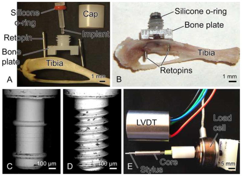
Illustration of the implant and motion device (A, B), and tips of pin (C) and screw-shaped (D) implants (diameter = 0.5 mm). The loading device (E) consists of a linear variable differential transformer (LVDT), a stylus (which fits into hole in cap of bone plate), a core (which slides into the LVDT) and a load cell connected to core of LVDT.
Table 1.
Experimental Groups
| Group | Implant | Type of interface | Displacement or loading protocol | Number of animals |
|---|---|---|---|---|
| 1 | Pin | BIGIa | Stable, 7 days | 14 |
| 2 | Pin | BIGI | 150 μm motion, 60 cycles/day, 1Hz, 7 days | 8 |
| 3 | Pin | BIGI | 300 μm motion, 60 cycles/day, 1Hz, 7 days | 5 |
| 4 | Pin | BIGI | 150 μm motion, 180 cycles/day, 1Hz, 7 days | 5 |
| 5 | Screw | BIGI | Stable, 7 days | 5 |
| 6 | Screw | BIGI | 150 μm motion, 60 cycles/day, 1Hz, 7 days | 8 |
| 7 | Screw | DBIIb | Stable, 7 days | 5 |
| 8 | Screw | DBII | 150 μm motion, 60 cycles/day, 1Hz, 7 days | 5 |
| 9 | Screw | DBII | 1.38 N force control, 43 μm motion, 60 cycles/day, 1Hz, 7 days | 5 |
BIGI, bone-implant-gap interface
DBII, direct-bone-implant-interface
2.2 Interfacial strain state around pins and screws
To estimate the interfacial strain fields, a first series of tests were done (n=6 for screws, n=6 for pins) in which micromotion systems were installed on small wood dowels with test implants placed in 0.8 mm diameter holes filled with a mixture of tantalum (Ta) powder (~0.5% by volume) in silicone-type rubber (www.reprorubber.com), which was used to simulate the elasticity of the early-state post-operative interfacial tissue. The Ta powder (particle size of 17 μm) provided radiopaque fiducial markers for use in strain analysis based on images from micro-CT images (Drs. David Hansen, Eric Ritman, and Andrew Vernocke, Physiological Imaging Research, Mayo Clinic, Rochester, MN). Micro-CT scanning was done using a custom-built scanner with the following components: (1) Phillips PW1830 x-ray generator and tube tower; (2) Newport MM3000 stage controller to control the stages (Newport TG160 translation stage; Newport RTN120PP rotation stage; Newport UT100.50PP focus stage); (3) Roper Scientific ST-138 Camera controller for Roper Scientific TE/CCD-1024 TKB/PI1 camera (1024 × 1024 CCD camera) and associated equipment including a CsI scintillator and 50mm F2.8N Nikon El-Nikkor Lens for coupling the scintillator output to the CCD camera, as well as a mechanical shutter interfaced with the camera. The above is all mounted on a Newport RS4000 optical table with 4 legs to float the table to isolate it from floor vibrations. The micro-CT stage allowed 360° rotation of samples the long axis of the in vitro tibiae in small angular steps of ~0.5°. Images were 1024 × 1024 pixels with a pixel size of about 6 μm.
Micro-CT scans were done before and after 150 μm implant displacement, images were processed in Analyze software (Mayo Clinic) to select the center plane of the implant by stepping through the slices, which were about 6 μm apart. Images before and after implant motion were analyzed using an optical strain measurement technique that measures microdisplacements using machine vision photogrammetry (DISMAP) [17, 18]. This method allowed determination of 2D strain contours of principal tensile and compressive strain in the gap region around the implant for the middle plane through the implant. In addition, FE models of the mock experiments with pins and screws were also formulated with a linear, elastic, isotropic, axisymmetric FE model (ABAQUS/CAE v. 6.6) using constitutive properties for silicone rubber, wood and the implant. To validate FE models of the mock experiments, measured strains via DISMAP were compared with those predicted by the FE model; there was a spatial and numerical agreement with experimentally-measured vs. FE-predicted strain fields [19] (Figs 2 and 3).
Figure 2.
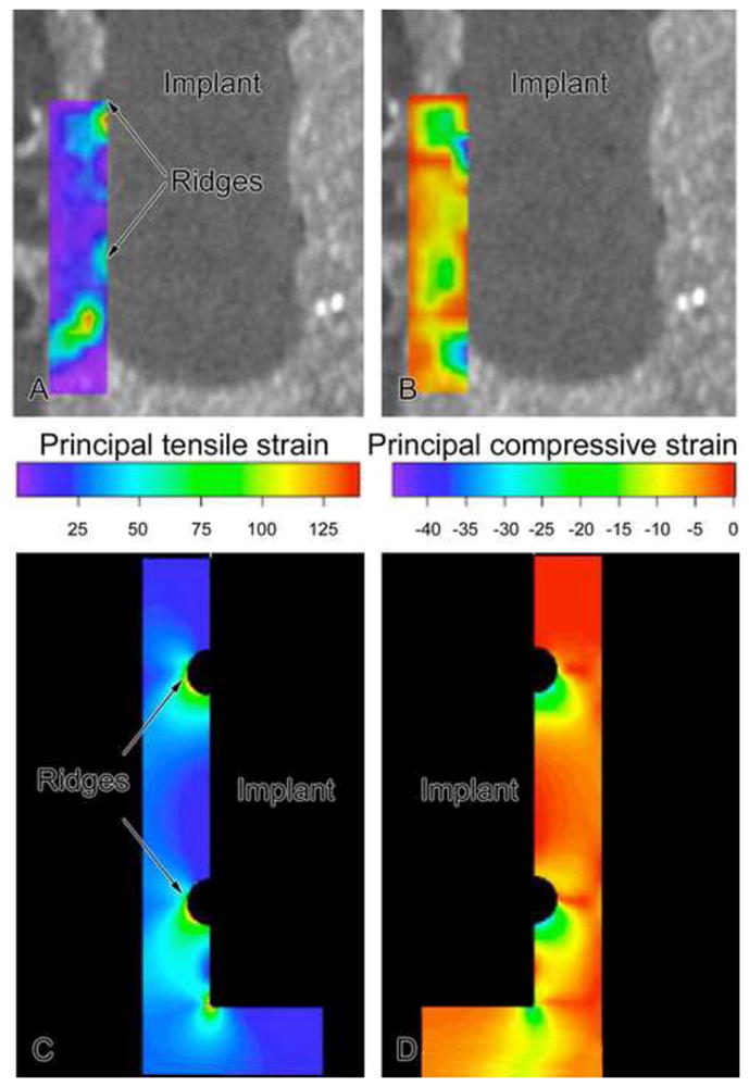
Contours of principal tensile (A) and compressive (B) strains around a pin-type implant as determined experimentally in a mock interface using DISMAP and micro-CT images. Axisymmetric finite element simulations for groups 1 and 2. For 150 μm motion of a pin implant, tensile and compressive strains of 30–100% were found at strain concentrations (ridges and beneath implant), with lower tensile and compressive principal strains (20%) at smooth sides of the pin. (N.B. The contour plots of tensile and compressive strain as displayed here on the left and right, respectively, should not be interpreted as only indicating strain fields on the left and right sides of the implant; instead in this axisymmetric FE model, one should mentally revolve each strain contour by 360° around the middle vertical axis to construct the strain distribution.).
Figure 3.
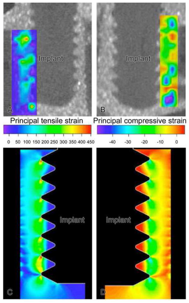
Contours of principal tensile (A) and compressive (B) strains around a screw-type implant as determined experimentally in a mock interface using DISMAP and micro-CT images. Axisymmetric finite element simulations for groups 4 and 5 are shown in C and D. For 150 μm motion of a screw implant, tensile strains exceeded 100% at crests of the screw threads and beneath the screw, while compressive strain magnitudes exceeded 30% at the crests of the screws. (N.B. The contour plots of tensile and compressive strain as displayed here on the left and right, respectively, should not be interpreted as indicating that only tensile strain occurred on the left side of the implant and only compressive strains occurred on the right side of the implant; instead in this axisymmetric FE model, one should mentally revolve each strain contour 360° around the middle vertical axis to construct the net strain distribution.)
To estimate strain fields around the implants in vivo, a second series of tests were done involving a 3-D FE model whose input geometry and material properties were based on in vivo data. First, the geometry of the 3-D FE model was based on geometric data for cortical bone and marrow as determined from histological data. We formulated a 3-D linear finite element model of the in-vivo situation using COMSOL Multiphysics® 4.2a (Fig. 4). We idealized the mouse tibia as a bi-material cylinder made of cortical bone and marrow. The implant’s main diameter was 0.8mm, and its tip was 0.5mm in diameter. The pin implant had two circumferential ridges of 0.05mm radius while the screw implant was idealized as being axisymmetric, with the threads matching a 0.5 UNM specification. The length of the implant’s tip was 1.33mm. With a pin implant, the uppermost circumferential ridge was positioned in the upper region of a trans-cortical hole in the tibia. The tibia’s cortical thickness was 0.16mm and the diameter of the marrow was 1.18mm. The length of the tibial segment was 11.0mm. The outer cortical surface of the bottom half of the tibial segment was fixed. For mechanical properties in the FE model, we assigned Young’s elastic moduli and Poisson’s ratios for bone, marrow and implant, respectively, as follows: for cortical bone 15 GPa and 0.33; for bone marrow, 10 MPa and 0.33; and for the implant, 432 MPa and 0.35 for the poly(L-lactide-co-D,L-lactide) implant. The properties of the interfacial region were determined from in vivo stiffness data, as explained next [20]. In the in vivo trials, we used our motion system to measure force on the implant as well as the resulting axial displacement into the interface. We then defined the ‘net’ stiffness as the ratio of force on the implant divided by implant displacement (measured relative to the bone plate mounted rigidly on the tibia). In our motion system, the rubber O-ring of known stiffness kw acted in parallel with the tissue interface of stiffness ki, so the net stiffness could be written as knet = kw + ki. Therefore, the interfacial stiffness could be determined via ki = knet−kw. Finally, using a series of 3-D FE models in Comsol 4.2a for each of the seven days of the in vivo experiments, we varied the material properties of the interface until the predicted stiffness from the FE model agreed with the measured in vivo interfacial stiffness ki for that specific day of the experiment. For example, for three representative groups of implants subjected to motion in the Bone-Implant-Gap Interface (BIGI), e.g., groups 2, 3 and 6 in Table 1, the in vivo stiffness of the interface, ki, ranged from about 0.003 N/μm at day 0 to about 0.035 N/μm at day 6 (Fig. 5). In turn, based on FE modeling, we found that these stiffness values for days 0 through 6 corresponded to the following values of Young’s elastic modulus (E) of interfacial tissue: 3.103, 4.766, 6.567, 9.331, 11.036, 10.854, and 17.559 MPa, with Poisson’s ratio constant at 0.33.
Figure 4.
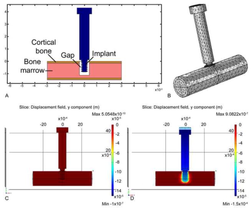
Formulation of a 3-D linear finite element model of the in-vivo situation. Fig. 4A illustrates schematically how the tip of the implant (pin or screw-shaped) resides partly in the cortical region and partly in the marrow region of the mouse tibia. In this illustration a “gap” is shown to depict the situation in the case of a BIGI; mechanical properties for the gap region were determined from our in vivo stiffness measurements (see text). Fig. 4B depicts the 3-D mesh structure for the model. Figs. 4C and D illustrate the displacement of the implant before (C) and after (D) 150 μm of axial downward motion.
Figure 5.
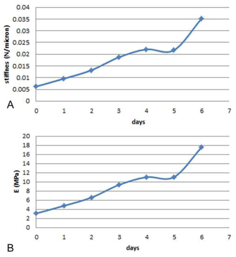
(A) Stiffness of the interface, ki, vs. time for three groups of implants tested in BIGI, namely, groups 2, 3 and 6. The interfacial stiffness (N/μm) was obtained from via ki = knet − kw as described in the text. (B) Plot of the time-variation of Young’s elastic modulus (E) of the interfacial tissue, corresponding to the stiffness values in Fig. 5A, as determined from matching finite element models to in vivo measurements of knet, the net interfacial stiffness
These interfacial mechanical properties were consistent with histological examination of the interface, which, for example, showed blood clot (fibrin) over the majority of the interface on the day of implantation (day 0) and immature bone at day 6. The captions of the figures in the paper indicate the properties used in the selected FE model. For example, in the FE models of the gap interface (BIGI) with pin and screw implants, the interfacial properties at day 2 were used in computing the strain state; the rationale for selecting the day 2 properties was our assumption that cells that had infiltrated the early healing site by day 2 represent the earliest cell population likely to be influenced by the strain fields. A different example is the case of a screw subjected to motion in a Direct-Bone-Implant-Interface (DBII), where there was no initial gap at the interface but where, instead, the screw threads engaged initially with bone of the tibia; in this case we selected interfacial bone properties that were 70% of the higher end of the modulus scale (e.g., 0.7 × 17.559 = 11.9 MPa), to simulate the properties of interfacial bone that was damaged by the drilling of the surgical site and the implant installation process.
2.3 Surgical procedure
To produce known strain fields during healing, pin (Fig. 1C) and screw-shaped (Fig. 1D) implants were installed in two different types of initial interface (Table 1): (1) BIGI, i.e. a 0.5 mm diameter implant in a 0.8 mm diameter hole; and (2) DBII, i.e. a 0.5 mm diameter screw-shaped implant inserted into a 0.4 mm diameter tapped hole. The initial nature of these interfaces is further described below.
Sixty male CD1 mice weighing 20 ± 5 g (Charles Rivers Canada; St-Constant, QC, Canada) were anesthetized with an intraperitoneal injection of a mixture of Ketalean (0.05 mg/g body weight; ketamine hydrochloride; Biomeda-MTC, Cambridge, ON, Canada), Rompun (0.005 mg/g body weight; xylazine; Bayer Inc., Toronto, ON, Canada) and Acevet (0.001 mg/g body weight; acepromazine maleate; Vetoquinol Inc., Lavaltrie, QC, Canada). The antero-medial side of the hind limb was shaved and cleaned with Baxedin® (Chlorhexidine Gluconate; Omega Laboratories, Montreal, QC, Canada). A 5 mm incision was made through the skin and the skin and muscle were gently moved aside to expose the periosteum. Two holes were drilled through both cortices using a 0.5 mm drill bit (Drill Bit City, Prospect Heights, IL). Titanium alloy retopins (0.60 mm in diameter, Edenta, Switzerland) were threaded through the side holes in the bone plate and into the cortices of the bone thereby fixing the bone plate to the bone. Using the center column of the bone plate as a guide, a transcortical hole was drilled at low speed using either a 0.4 mm (DBII) or 0.8 mm drill bit (BIGI) (Drill Bit City). Implants were inserted into the hole with a silicone rubber O-ring (model 40SL, Apple Rubber Products, Lancaster, NY) placed between the head of the implant and the center column of the bone plate. The cap was screwed onto the center column of the bone plate. The drilling sites were irrigated with physiological saline. The muscle was sutured with 4-0 chromic gut sutures and the skin was closed with 4-0 silk sutures (distributed by Patterson Dental Supply Inc.). The surgical site was cleaned and disinfected with 70% ethanol. The animals received an injection of Temgesic® (0.05 mg/kg, Buprenorphine hydrochloride, Reckitt and Colman, Hull, UK) after surgery, and were fed with soft food containing Temgesic®. All animal procedures and experimental protocols were approved by the Comité de déontologie de l’expérimentation sur les animaux of Université de Montréal.
2.4 Tissue processing and histology
After seven days, animals were anesthetized with a 20% chloral hydrate solution (0.4 mg/g body weight; Fisher Scientific, Whitby, ON, Canada) and sacrificed. The tibia were dissected out and immersed in a fixative solution consisting of 4% paraformaldehyde (BDH; Toronto, ON, Canada) and 0.1% glutaraldehyde (Electron Microscopy Sciences, Washington, PA) in 0.08M sodium cacodylate (Electron Microscopy Sciences) buffer containing 0.05% calcium chloride (Sigma-Aldrich Canada Ltd, Oakville, ON, Canada), pH 7.2, for 3 hours at 4°C. They were then washed with 0.1M sodium cacodylate buffer, pH 7.2 and processed for embedding in methylmethacrylate resin as previously described [21]. Five to eight μm-thick longitudinal sections were cut using a Reichert-Jung Polycut E horizontal microtome (Leica, Heidelberg), collected on superfrost-plus slides for histology, deplasticized with toluene, rehydrated with decreasing concentrations of ethanol, and stained according to the Goldner’s trichrome protocol.
Some calcified methylmethacrylate embedded samples were cut along the sagittal plane, using an IsoMet® Low Speed saw (Buehler Canada, Markham, ON, Canada), to produce 1 mm thick sections. The retopins and micromotion device on this section were then pried apart as described previously [22] and the tissue was processed for reembedding in Epoxy resin (Electron Microscopy Sciences, Washington, PA). One μm thick semi-thin sections were cut with diamond knives on a Reichert Jung Ultracut E ultramicrotome and stained with toluidine blue. Histological observations were done an Axiophot light microscope (Carl Zeiss, Oberkochen, Germany).
2.5 Image analysis
Calcified Goldner’s trichrome stained longitudinal sections through the mid-plane of implants in the tibia allowed measurement of the distance between implant surface and first hit of mineralized bone (‘bone-implant distance’) using the Image-J software (NIH). The mean bone-implant distance over the entire implant periphery was based on data taken from ~ 30 evenly-spaced points around the periphery of each implant.
2.6 Statistical analyses
Statistical tests for differences in distributions of bone-implant distance for stable and loaded groups were conducted using Kolmogorov-Smirnov or two sample tests and using 95% confidence intervals; p < 0.05 was considered significant.
3. RESULTS
3.1 Analysis of interfacial strains around pins and screws in the “mock” interface
The strain fields around pin (Fig. 2) and screw-shaped (Fig. 3) implants in a BIGI were characterized using experimental strain measurements from DISMAP and FE models (e.g., see Figs. 2, 3 as well as 6 and 9). The majority of the interface in pin-shaped implants had low or moderate principal tensile (Figs. 2A and 2C, 6L) (less than ~25%) and compressive (Figs. 2B, 2D, 6K) (less than ~ 10%) strains. High tensile (e.g., 30% to over 100%) and compressive (e.g., > 30–50%) strain zones were mainly concentrated at the two circumferential ridges of the pin-shaped implant and beneath its base. These analyses indicated that, as expected, the largest strains in the interface occurred closest to those parts of the implant surface having sharp corners and small radii of curvature.
Figure 6.
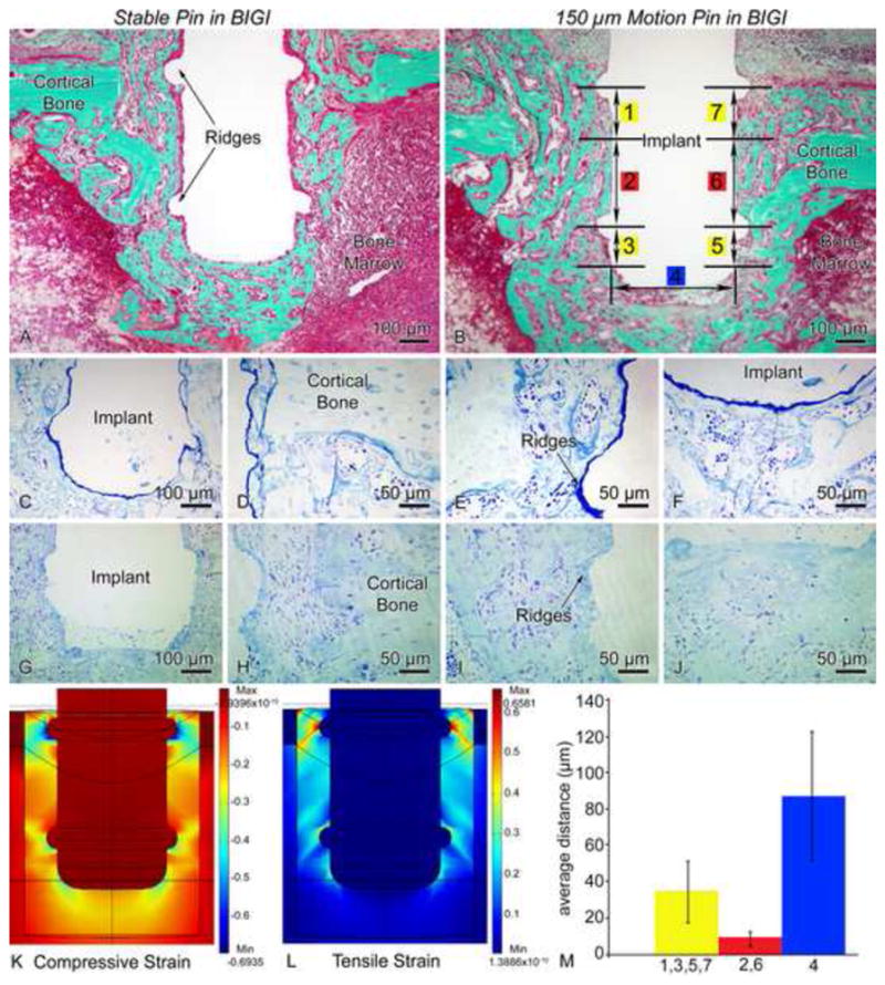
Light micrographs illustrating the histological appearance of (A, C–F) stable (group 1) and (B, G–J) 150 μm motion (group 2) pin-shaped implant placed in a bone-implant-gap interface (BIGI) for 7 days. Histological observations reveal that newly formed bone is present near the circumferential ridges (A, D–E) and beneath the base (A, F) of stable implants. In implants subjected to loading (B, G–J), some bone formation is noted in these high strain regions, but a granulation tissue consisting of fibroblasts, red blood cells and inflammatory cells can also be observed. Toluidine blue (C–J) stained semi-thin sections allow a better resolution of the interfacial tissue than what is observed in Goldner stained thick sections (A, B). (K, L) 3-D finite element predictions of principal compressive (K) and tensile (L) strains in the BIGI when the Young’s modulus of the BIGI had day 2 properties, i.e., 6.56 MPa (M) For pin-shaped implants moving 150 μm in the BIGI, the mean local bone-implant distance at high strain regions (circumferential ridges = 1,3,5,7 and base = 4) was larger than at the lower strain regions (smooth sides of the pin = 2,6) of the same pin (bars show 99% confidence intervals).
With screw-shaped implants in the gap-type (BIGI) interface (Figs. 3, 9D), principal strains had a periodic pattern that approximately matched the multiple crests of the screw threads. More areas of strain concentration were found in this interface due to the multiple screw threads. Very large tensile (> 100%) and compressive (> 40%) strains (Figs. 3A, 3C, 9C and 9D) were found at the tip of each implant’s thread, however, the principal tensile and compressive strain magnitudes or the remainder of the interface were at low or moderate magnitudes (< 30%) (Figs. 3B, 3D, 9C and 9D).
Figure 9.
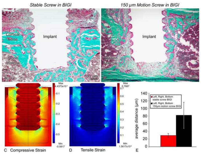
Light micrographs illustrating the histological appearance of (A) stable (group 5) and (B) screws-shaped implant moving 150 μm in a bone-implant-gap interface (BIGI) (group 6). (A) Bone formation along the interface with the implant is seen in the stable case. (B) However, the strains generated in the loaded implant evidently disrupted bone healing and lead to the formation of a fibrous tissue around the implant. (C, D) Finite element analyses employing day 2 properties for the BIGI (i.e., 6.56 MPa) predicted regions of large (i.e. 30–100%) tensile (C) and compressive (D) principal strains at the tips of the screw threads and beneath the screw. (E) There was a significantly larger bone-implant distance in the motion cases at 7 days co-localizing with these large strains fields (bars show 95% confidence intervals).
While high principal tensile and compressive strains were present in certain regions immediately next to both pin and screw implants as tested in the mock interfaces, the relative spatial extent of these regions was only about 12% (pins) to 15% (screws) of the whole interface. The remainder of the interface experienced lower-magnitude strains (< 30%).
3.2 Influence of interfacial strain on interfacial healing
In order to test the hypothesis that high principal strain magnitude near the implant surface disrupted the bone regeneration process, the distance between the implant surface and the “first hit” of mineralized bone (i.e. the bone-implant distance) was measured at approximately 30 evenly-spaced locations along each implant’s periphery in calcified sections.
3.2.1. Pin-shaped implant stable (Group 1) vs. 150 μm motion in BIGI (Group 2)
In regions of lower principal tensile and compressive strains, newly formed bone was observed around pin shaped implants subjected to 150 μm motion with a BIGI (compare Figs. 6A and 6B). In contrast, in regions where high principal tensile and compressive strains existed (based on experimental and FE strain analyses) (Fig. 6K), cellular debris and red blood cells were found, without bone matrix deposition, which is consistent with localized tissue damage at high strain regions (compare Figs. 6C–F and 6G–J). Experimental and FE strain analyses showed that the highest principal tensile and compressive strains (> 30%) occurred close to the implant surface, at the two circumferential ridges of the pin-shaped implant and beneath its base (Figs. 6K and 6L). The bone-implant distance at these strain-concentrating features significantly differed from those in lower strain regions of the same implant that underwent 150 μm motion (Fig. 6M).
3.2.2 Pin-shaped implant 300 μm motion in BIGI (Group 3)
Signs of disruption of bone healing were more evident throughout the interface when the axial displacement of the pin implant in a BIGI was increased to 300 m (compare Figs. 6A and 7A). A young granulation tissue showing fibroblasts, blood extravasations, and inflammatory cells was found at the bone-implant interface, and there were fewer bone trabeculae seen in the bone marrow cavity. The spatial distribution of high strain extended farther out from the two circumferential ridges and base of the pin-shaped implant as compared to the pins with 150 μm motion (group 2) since there is a larger up-and-down (axial) motion of the pin implant subjected to 300 μm vs. 150 μm (compare Figs. 6K, 6L, 7C and 7D). The bone-implant distance was significantly larger for 300 m of displacement than with 150 μm of displacement (Fig. 7B).
Figure 7.

(A) Light micrographs of the 300 μm-motion pin in a bone-implant-gap interface (BIGI) for 7 days (group 3). Survey analysis revealed less newly formed bone and a broader region of granulation tissue along the high strain regions of the implant. (B) For pin-shaped implant moving 300 μm in the BIGI (with E = 6.56 MPa, i.e., day 2 properties), a larger local bone-implant distance was found for motion than for stable case (group 1) (bars show 95% confidence intervals). (C, D) Finite element predictions of interfacial principal compressive (C) and tensile (D) strains. Compared with the strain fields in Fig 7, this case shows larger strain magnitudes everywhere in the interface, e.g., the largest magnitudes of about 60% at the circumferential ridges and base of the implant,
3.2.3 Pin-shaped implant 150 μm motion, 3 sessions of 60 cycles in BIGI (Group 4)
In order to determine whether the daily number of cycles of micromotion might affect the strain history and related mechanobiological events occurring at the bone-implant interface, three daily sessions of 150 μm (60 cycles per loading for a total of 180 cycles per day) were applied to a pin-shaped implant placed in BIGI (group 4). Around the two circumferential ridges and beneath the base of the implant, bone healing was further disrupted in these repetitively highly-strained regions as compared to pin implants subjected to 150 μm of motion for only 60 cycles per day (compare Figs 6C–F and 8A–D). No signs of newly formed bone were noted in this experimental group with 180 cycles/day; instead only a thicker area of granulation tissue was observed.
Figure 8.
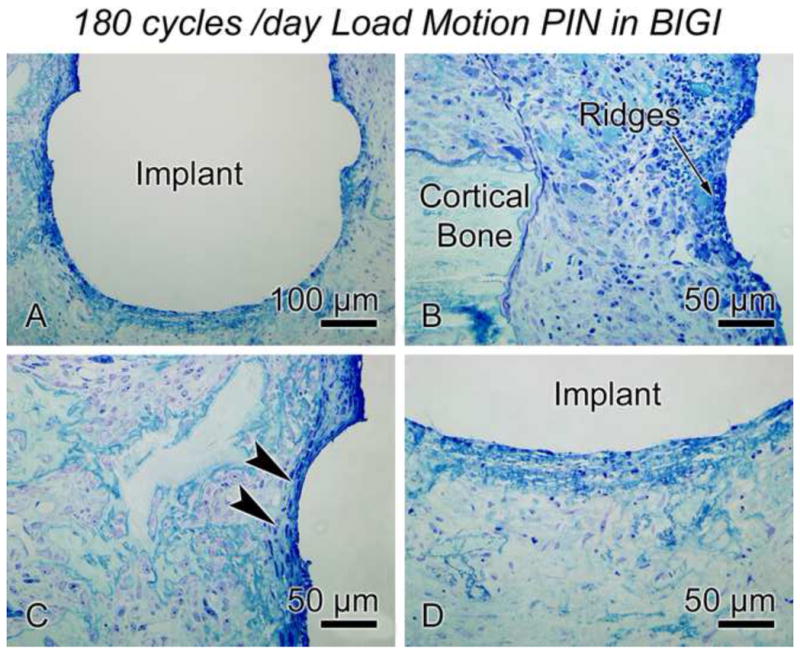
Light micrographs of the 150 μm-motion pin (180 cycles per day) in a bone-implant-gap interface (BIGI) for 7 days (group 4). When increasing the daily number of cycles per day, bone healing around the implant was disrupted over more of the interface than in the case of the 150 μm-motion pin for only 60 cycles per day. The bone-implant interface was covered by a granulation tissue.
3.2.4 Screw-shaped implant stable (Group 5) vs. 150 μm motion in BIGI (Group 6)
In stable screw-shaped implants placed in BIGI, newly formed bone was observed around each thread of the implant (Fig. 9A). When 150 μm axial micromotion was applied to these implants, osteoid and newly formed bone was also noted around some threads. However, a granulation tissue was interposed between the new bone and the moving implant, precluding a direct bone-implant contact (Fig. 9B). Tissue at the crests of the threads was subjected to high tensile and compressive strains (Fig. 9C). High compressive strains were also predicted at the bottom of the implant, but not as much tensile strain. The bone-implant distance (Fig. 9E) was significantly smaller in stable implants than the ones subjected to micromotion, in view of the large predicted strains close to the surface of the moving screw in the BIGI (Fig. 9D).
3.2.5 Screw-shaped implant stable (Group 7) vs. 150 μm motion in DBII (Group 8)
We threaded screw-shaped implants into a smaller hole (0.4 mm in diameter instead of 0.8 mm) and created an initial DBII. This interface consisted of both small gaps and bone contact, which resembles typical clinical cases of so-called “immediate loading” with commonly-used threaded oral/maxillofacial implants or orthopaedic bone screws. While newly formed bone was observed by day 6 around screw threads in stable implants, survey analyses showed the presence of a mixture of fibroblastic cells and non-mineralized matrix in implants subjected to 150 μm micromotion (compare Figs. 10A and 10B). The shape of the threads was also distorted in the histological section of the loaded cases, this distortion may have arisen from deformation of the polymeric material during axial micromotion of the implant or from sectioning artefact. For 150 μm micromotion, this type of interface showed principal strains extending over a larger region of the interface (Figs. 10C and 10D) than with pin implants, and this strain state correlated with a significantly larger bone-implant distance in the micromotion group than in the stable screws placed in DBII (Fig. 10E).
Figure 10.
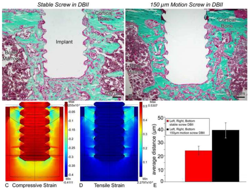
Light micrographs of (A) stable (group 7) and (B) screws moving 150 μm (group 8) in a direct-bone-implant-interface (DBII). A difference in the shape and orientation of the threads of loaded implants can be observed in implants subjected to micromotion (B). (C, D) Finite element analyses predicted very large (i.e., 30–100%) tensile (C) and compressive (D) principal strain magnitudes at screw thread tips and beneath the screw in this DBII. Due to expected damage from drilling etc., we used a Young’s elastic modulus for the bone adjacent to the implant that was 70% of the largest value that we measured in the healing interface, i.e., we used 11.9 MPa (= 0.7 × 17 MPa). (E) There was a significantly larger bone-implant distance for motion cases vs. stable, which correlated with the localization of these large strains (95% confidence interval).
3.2.6 Screw-shaped implant with force-control motion in DBII (Group 9)
We also subjected a group of screw-shaped implants to force-control micromotion, in which the implants were loaded to the same peak force (1.38N, average displacement of ~ 43 μm) that occurred during displacement-controlled micromotion of 150 μm for the same type of screws in BIGI. However, due to the initial direct bone-implant interface (as opposed to the BIGI), the axial micromotion occurring under this loading averaged 43 μm rather than 150 μm. Histological observation did not reveal any obvious differences concerning bone formation between stable and loaded implants (compare Figs. 10A and 11A). Newly formed bone around each thread and beneath the bottom of the screw-shaped implant was noted (Figs. 11B–E). In these regions, no fibrous tissue formation was observed. Analyses of strain fields revealed smaller interfacial principal strain magnitudes than in the other screw groups (e.g., peak strain magnitude of about 1/3 the peak magnitude in the 150 μm screw group 8) (Figs. 11F and 11G). Nearly direct bone-implant apposition occurred in the force-control motion case (Fig. 11H), which did not statistically differ from the bone-implant distance measured for stable implants in the DBII.
Figure 11.
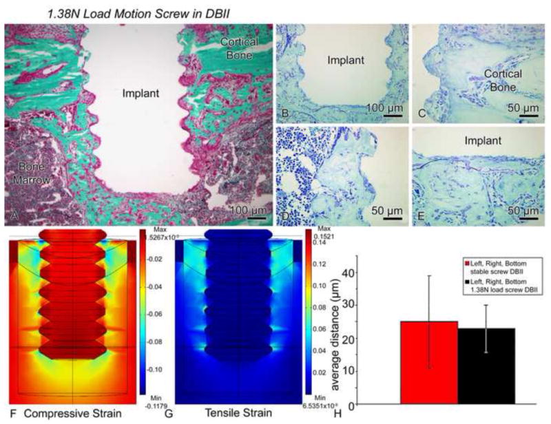
(A–E) Light micrographs of illustrating the histological appearance of screws that have been moved axially by only 17–70 μm (average of 43 μm) in a direct-bone-implant-interface (DBII) (1.38N load, group 9). Histological observations of Goldner (A) and toluidine blue stained sections (B–E) showed nearly direct bone-implant apposition around the threads (C–D) and beneath the base of the implant (E). (F, G) Compared to the situation in Figure 10, relatively small magnitudes of the principal compressive (F) and tensile (G) strains were predicted at the interfaces of the implants subjected to motion in this group. Due to expected damage from drilling etc., we used a Young’s elastic modulus for the bone adjacent to the implant that was 70% of the largest value that we measured in the healing interface, i.e., we used 11.9 MPa (= 0.7 × 17 MPa). (H) There was no difference in the bone-implant distance values for stable (group 7) vs. motion cases (group 9) (bars show 95% confidence intervals).
4. DISCUSSION
The premise of our work has been that a better understanding of the role of strain in healing tissue is beneficial because strain is a fundamental mechanical measure of deformation, which can help define danger limits for tissue just as it does for common engineering materials. Indeed, this concept has also been promoted in orthopaedics and fracture healing by workers such as by Perren [23]. In this study, we have tested pin and screw-shaped implants subjected to different axial motion protocols in a BIGI or DBII as a means to vary the local interfacial strain fields. Notably, our loading system allowed us to enforce the same motion on the implants throughout the 7-day period of the study even though there were changes in the tissue properties, as seen, for example, in our data on stiffness of the bone-implant interface during healing [24]. It is also important to note that our measurements of bone-implant distances and histology etc. were done on calcified tissues sections in which implants were not removed. This enabled the characterization of the healing process in sections with good geometric fidelity of the tissue-implant interface - e.g., without any interfacial damage due to removal of the implant prior to histology.
Beyond our in vivo stiffness tests [24], there are little data in the literature about how the tissue properties of healing bone-implant interfaces vary with healing time. There are similarities and differences in bone healing in mice vs. higher-order mammals, and we have discussed them in earlier implant experiments work with the mouse model [25]. While we also recognize that the tissue properties we have used for FE modelling are simplified and linear, however input tissue properties were derived from in vivo stiffness data, and therefore give some confidence in the validity of the FE modeling. Our choice to formulate the FE model using elastic isotropy was merely the simplest starting point in modeling the interfacial tissues, which no doubt are more complicated in their actual constitutive properties. Certainly one limiting factor in developing such FE models is the lack of data about the evolving interfacial tissue properties.
Our FE model assumes linear isotropic elasticity for the bone and non-mineralized interfacial tissues in the gap-type interfaces. Generally, it’s understood that bone is anisotropic, and that the early non-mineralized tissue around an implants in the gap interface is likely to be anisotropic, non-linear, and perhaps also biphasic, that is containing fluid and solid phases. We do not yet have full data to guide selection of more complicated constitutive properties to use in our FE models. However, we did show that we were able to experimentally measure significant changes in the mechanical properties (e.g., stiffness) of the interfacial tissues over the course of the healing. Based on those measurements, we then estimated constitutive properties – albeit simplified linear elastic properties – for the interface. We are aware of the limitations but feel our approach is a step in the right direction of obtaining true interfacial properties that could lead to more accurate constitutive modeling in the future.
Taken together, our results showed that, higher principal compressive and tensile strains were noted in pins and screws subjected to motion in comparison to stable implants. In pin-shaped implants, the highest strains were concentrated at the two circumferential ridges and beneath the implant’s base, while for screw implants, high strains existed at the crest of each thread and at the implant’s base. For implants placed in the gap interface (BIGI), the bone-implant-distance was larger in the 300 μm motion pin group (group 3) than in the 150 μm motion pin group (group 2). For moving screws in the BIGI, high strains occurred nearly everywhere close to the implant’s surface and accordingly, the bone-implant distance was larger than with stable screws. Also our analyses revealed that the bone-implant-distance for the 150 μm screws (group 6) in BIGI was about equal to bone-implant distance for the 300 μm pins in the same interface, which might be related to their similar high-magnitude strain profiles. However, with 150 μm motion, in the BIGI, one interesting observation was that the bone-implant distance averaged over the total interface of pins was less than that for the screws, and not different from the bone-implant distance averaged over the total interface of the stable implants. This finding is consistent with our observation that the spatial extent of strain around the 150 μm pin was not as large as in the case of the 150 μm screws or the 300 μm pin in BIGI. These findings indicate that the local interfacial strain distribution around implants - e.g., at the spatial level of 10s of microns - does influence peri-implant bone formation.
For the implants placed in DBII, a larger bone-implant distance was measured in 150 μm motion screws (group 8) than in stable screws (group 7), which consistent with what would be predicted based on the very large-magnitude interfacial principal strain fields generated in the motion case. Interestingly, for the screws in the force-control micromotion group (group 9), the small implant displacement of about 43 μm (which accompanied the small force) produced lower strain levels throughout at the interface than in the 150 μm case, and in turn, it was not surprising to find no significant difference in the bone-implant distance when compared to the stable implants.
The present results indicate that the largest bone-implant distance (mean values ranging from 40–80 μm) occurred for motion implants having high interfacial principal tensile and/or strains (> 30 %) over nearly the entire interface (i.e. groups 2, 3 and 6). These data are consistent with other data from both in vitro and in vivo studies. For example, application of cyclic strain (~ 3%) on mesenchymal stem cells enhanced their production of a mineralized matrix [26], and in other cell culture experiments, osteoblasts responded to high strain magnitudes by aligning perpendicularly to the strain direction [27]. Finite element analyses have suggested that the local strain distribution had a significant impact on the biological activity of the bone tissue adjacent to the implant surface [28]. Also, FE analyses of chondrocytic condensations predicted patterns of principal tensile strains of up to 15% [29]. Studies on fracture healing have proposed that interfragmentary strain levels of about 10% were permissive of bone regeneration and healing [30] while high strains levels (> 30%) triggered fibrocartilage formation. In the case of distraction osteogenesis, tensile strains of approximately 10–12.5% were beneficial for new bone formation [31]. Also, appositional bone formation around oral implants occurred when local magnitude strains at the interface were less than 8%, while distortional tissue strains of approximately 3% were more favourable for bone formation [12].
From these various studies above, it can be noted that they were all testing the idea that the deformation state (strain state) of a healing tissue plays a role in regulating the interfacial biology. Along these lines, several mechanobiological theories asserting a relationship between various biomechanical parameters (including strain and stress) and tissue biology have been proposed to explain fracture healing [32, 33], distraction osteogenesis [32] and healing at bone-implant interface [12]. However, in assessing these models, it is still unknown which mechanical variable, e.g., stress, strain, or a combination of both, etc., is most important in terms of mechanical factors that disrupt bone healing. Certainly some studies have shown that premature loading induced fibrous tissue formation at the implant interface [14, 34], although it has been noted that fibrous encapsulation is attributable to excessive micromotion that can accompany the loading and not the immediate loading per se [6]. Although our micromotion conditions in the current work did not create such fibrous encapsulation even when very large strains were produced (e.g., group 3), the presence of a granulation tissue is consistent with an eventual formation of fibrous tissue, if a longer experimental loading time were to be used in our mouse model. The different parameters, such as loading frequency, magnitude and rate, timing and healing period might also explain this discrepancy with the literature. Our experiments were done for a healing period of 7 days, with motion only for 1 minute per day (except in group 4). Several studies provided evidence for the dependence of bone response to the loading frequency [35–37]. In addition to the total number of motion cycles per day, the manner in which those cycles were delivered could also play a critical role during bone healing [10, 38]. For example, 2 sessions per day delivered at 90 cycles/session might produce a different biological result than 12 sessions per day delivered at 15 cycles/session even though both cases would have a total of 180 motion or loading cycles. A possible explanation for this suggestion is that the application of multiple loading cycles affects the rate of accumulation of damaged in the tissue vs. the rate of repair in the tissue.
In conclusion, until osseointegration remains the basis for implant success, we will be facing biomechanical issues. We suggest that implant micromotion per se may not be the decisive factor in interfacial healing; instead, based on our studies, we assert that a critical factor in the biological response during implant micromotion is the interfacial strain magnitude and its spatial distribution associated with such micromotion. From a clinical, “translational” point of view, there are some useful implications of this finding. For example, a very smooth-surfaced implant moving, say, 30 μm, might not create high interfacial strain concentrations, whereas a very rough-surfaced implant (of the same overall shape) moving the same amount could create high interfacial strain levels; the key issue is the local strain state in the interface, which depends on the surface geometry along with other factors, as we have explained. But beyond just the strain magnitude and distribution, it is also likely that additional factors - such as the number of strain cycles per day - are also likely to be important in regulating cellular responses.
Acknowledgments
The authors are grateful to Dan Nicolella (Southwest Research Institute, San Antonio, TX) for helping with strain analyses by DISMAP. We also thank Dr. Eric Ritman, Dave Hansen, and Andrew Vercnocke of the Mayo Clinic, Rochester, MN for assistance with micro-CT imaging.
This work was supported by the Canadian Institutes of Health Research (CIHR), NIH grant 7R01EB000504-07 and the Canadian Foundation for Innovation (CFI).
Footnotes
Publisher's Disclaimer: This is a PDF file of an unedited manuscript that has been accepted for publication. As a service to our customers we are providing this early version of the manuscript. The manuscript will undergo copyediting, typesetting, and review of the resulting proof before it is published in its final citable form. Please note that during the production process errors may be discovered which could affect the content, and all legal disclaimers that apply to the journal pertain.
References
- 1.Robling AG, Castillo AB, Turner CH. Biomechanical and molecular regulation of bone remodeling. Annu Rev Biomed Eng. 2006;8:455–498. doi: 10.1146/annurev.bioeng.8.061505.095721. [DOI] [PubMed] [Google Scholar]
- 2.Skerry TM. The response of bone to mechanical loading and disuse: fundamental principles and influences on osteoblast/osteocyte homeostasis. Arch Biochem Biophys. 2008;473:117–123. doi: 10.1016/j.abb.2008.02.028. [DOI] [PubMed] [Google Scholar]
- 3.Mouzin O, Soballe K, Bechtold JE. Loading improves anchorage of hydroxyapatite implants more than titanium implants. J Biomed Mater Res. 2001;58:61–68. doi: 10.1002/1097-4636(2001)58:1<61::aid-jbm90>3.0.co;2-s. [DOI] [PubMed] [Google Scholar]
- 4.Van OH, Duyck J, Vander SJ, Van Der Perre G, De CM, Lievens S, Puers R, Naert I. The influence of bone mechanical properties and implant fixation upon bone loading around oral implants. Clin Oral Implants Res. 1998;9:407–418. doi: 10.1034/j.1600-0501.1996.090606.x. [DOI] [PubMed] [Google Scholar]
- 5.Simmons CA, Meguid SA, Pilliar RM. Differences in osseointegration rate due to implant surface geometry can be explained by local tissue strains. J Orthop Res. 2001;19:187–194. doi: 10.1016/S0736-0266(00)90006-8. [DOI] [PubMed] [Google Scholar]
- 6.Szmukler-Moncler S, Salama H, Reingewirtz Y, Dubruille JH. Timing of loading and effect of micromotion on bone-dental implant interface: review of experimental literature. J Biomed Mater Res. 1998;43:192–203. doi: 10.1002/(sici)1097-4636(199822)43:2<192::aid-jbm14>3.0.co;2-k. [DOI] [PubMed] [Google Scholar]
- 7.Duyck J, Slaets E, Sasaguri K, Vandamme K, Naert I. Effect of intermittent loading and surface roughness on peri-implant bone formation in a bone chamber model. J Clin Periodontol. 2007;34:998–1006. doi: 10.1111/j.1600-051X.2007.01135.x. [DOI] [PubMed] [Google Scholar]
- 8.Duyck J, Vandamme K, Geris L, Van OH, De CM, Vandersloten J, Puers R, Naert I. The influence of micro-motion on the tissue differentiation around immediately loaded cylindrical turned titanium implants. Arch Oral Biol. 2006;51:1–9. doi: 10.1016/j.archoralbio.2005.04.003. [DOI] [PubMed] [Google Scholar]
- 9.Vandamme K, Naert I, Geris L, Vander SJ, Puers R, Duyck J. Influence of controlled immediate loading and implant design on peri-implant bone formation. J Clin Periodontol. 2007;34:172–181. doi: 10.1111/j.1600-051X.2006.01014.x. [DOI] [PubMed] [Google Scholar]
- 10.Rubin CT, McLeod KJ. Promotion of bony ingrowth by frequency-specific, low-amplitude mechanical strain. Clin Orthop Relat Res. 1994:165–174. [PubMed] [Google Scholar]
- 11.De SE, Jaecques S, Vandamme K, Vander SJ, Naert I. Positive effect of early loading on implant stability in the bi-cortical guinea-pig model. Clin Oral Implants Res. 2005;16:402–407. doi: 10.1111/j.1600-0501.2005.01156.x. [DOI] [PubMed] [Google Scholar]
- 12.Simmons CA, Meguid SA, Pilliar RM. Mechanical regulation of localized and appositional bone formation around bone-interfacing implants. J Biomed Mater Res. 2001;55:63–71. doi: 10.1002/1097-4636(200104)55:1<63::aid-jbm90>3.0.co;2-v. [DOI] [PubMed] [Google Scholar]
- 13.Brunski JB. In vivo bone response to biomechanical loading at the bone-dental implant interface. Adv Dent Res. 1999;13:99–119. doi: 10.1177/08959374990130012301. [DOI] [PubMed] [Google Scholar]
- 14.Bragdon CR, Burke D, Lowenstein JD, O’Connor DO, Ramamurti B, Jasty M, Harris WH. Differences in stiffness of the interface between a cementless porous implant and cancellous bone in vivo in dogs due to varying amounts of implant motion. J Arthroplasty. 1996;11:945–951. doi: 10.1016/s0883-5403(96)80136-7. [DOI] [PubMed] [Google Scholar]
- 15.Gapski R, Wang HL, Mascarenhas P, Lang NP. Critical review of immediate implant loading. Clin Oral Implants Res. 2003;14:515–527. doi: 10.1034/j.1600-0501.2003.00950.x. [DOI] [PubMed] [Google Scholar]
- 16.Leucht P, Kim JB, Wazen R, Currey JA, Nanci A, Brunski JB, Helms Effect of mechanical stimuli on skeletal regeneration around implants. Bone. 2007;40:919–930. doi: 10.1016/j.bone.2006.10.027. [DOI] [PMC free article] [PubMed] [Google Scholar]
- 17.Kim DG, Brunski IB, Nicolella DP. Microstrain fields for cortical bone in uniaxial tension: optical analysis method. Proc Inst Mech Eng H. 2005;219:119–128. doi: 10.1243/095441105X9291. [DOI] [PubMed] [Google Scholar]
- 18.Nicolella DP, Nicholls AE, Lankford J, Davy DT. Machine vision photogrammetry: a technique for measurement of microstructural strain in cortical bone. J Biomech. 2001;34:135–139. doi: 10.1016/s0021-9290(00)00163-9. [DOI] [PubMed] [Google Scholar]
- 19.Currey JND, Brunski JB. Characterization of the mechanical environment at the implant interface: An in vitro study. Bioengineering Conference (Proceedings of BIO2006); June 21–25 2006; Amelia Island Plantation, Amelia Island, FL. 2006. [Google Scholar]
- 20.Currey JA, D’Anjou C, Leucht P, Wazen R, Helms JA, Nanci A, Brunski JB. Determination of in vivo mechanical properties of healing interfacial tissue at an implant site in bone. 2nd International Conference on Mechanics of Biomaterials & Tissues; Lihue, Kaua’I, Hawaii. Dec 9–13, 2007. [Google Scholar]
- 21.Laboux O, Ste-Marie LG, Glorieux FH, Nanci A. Quantitative immunogold labeling of bone sialoprotein and osteopontin in methylmethacrylate-embedded rat bone. J Histochem Cytochem. 2003;51:61–67. doi: 10.1177/002215540305100108. [DOI] [PubMed] [Google Scholar]
- 22.Nanci A, McCarthy GF, Zalzal S, Clokie CML, Warshawsky H, McKee MD. Tissue response to titanium implants in the rat tibia: ultrastructural, immunocytochemical and lectin-cytochemical characterization of the bone-titanium interface. Cells Mater. 1994;4:1–30. [Google Scholar]
- 23.Perren SM. Evolution of the internal fixation of long bone fractures. The scientific basis of biological internal fixation: choosing a new balance between stability and biology. J Bone Joint Surg Br. 2002;84:1093–1110. doi: 10.1302/0301-620x.84b8.13752. [DOI] [PubMed] [Google Scholar]
- 24.D’Anjou C, Currey JA, Wazen R, Nanci A, Leucht P, Helms JA, Brunski JB. Stiffness of the bone-implant interface as an indicator of bone healing. 53rd Annual Meeting of the Orthopaedic Research Society; February 11–14, 2007; San Diego, CA. 2007. [Google Scholar]
- 25.Colnot C, Romero DM, Huang S, Rahman J, Currey JA, Nanci A, Brunski JB, Helms JA. Molecular analysis of healing at a bone-implant interface. J Dent Res. 2007;86:862–867. doi: 10.1177/154405910708600911. [DOI] [PubMed] [Google Scholar]
- 26.Simmons CA, Matlis S, Thornton AJ, Chen S, Wang CY, Mooney DJ. Cyclic strain enhances matrix mineralization by adult human mesenchymal stem cells via the extracellular signal-regulated kinase (ERK1/2) signaling pathway. J Biomech. 2003;36:1087–1096. doi: 10.1016/s0021-9290(03)00110-6. [DOI] [PubMed] [Google Scholar]
- 27.Claes LE, Heigele CA, Neidlinger-Wilke C, Kaspar D, Seidl W, Margevicius KJ, Augat P. Effects of mechanical factors on the fracture healing process. Clin Orthop Relat Res. 1998;355S:S132–S147. doi: 10.1097/00003086-199810001-00015. [DOI] [PubMed] [Google Scholar]
- 28.Meyer U, Vollmer D, Runte C, Bourauel C, Joos U. Bone loading pattern around implants in average and atrophic edentulous maxillae: a finite-element analysis. J Craniomaxillofac Surg. 2001;29:100–105. doi: 10.1054/jcms.2001.0198. [DOI] [PubMed] [Google Scholar]
- 29.Henderson JH, de la Fuente L, Romero D, Colnot CI, Huang S, Carter DR, Helms JA. Rapid growth of cartilage rudiments may generate perichondrial structures by mechanical induction. Biomech Model Mechanobiol. 2007;6:127–137. doi: 10.1007/s10237-006-0038-x. [DOI] [PubMed] [Google Scholar]
- 30.Claes L, Eckert-Hubner K, Augat P. The effect of mechanical stability on local vascularization and tissue differentiation in callus healing. J Orthop Res. 2002;20:1099–1105. doi: 10.1016/S0736-0266(02)00044-X. [DOI] [PubMed] [Google Scholar]
- 31.Loboa EG, Fang TD, Warren SM, Lindsey DP, Fong KD, Longaker MT, Carter DR. Mechanobiology of mandibular distraction osteogenesis: experimental analyses with a rat model. Bone. 2004;34:336–343. doi: 10.1016/j.bone.2003.10.012. [DOI] [PubMed] [Google Scholar]
- 32.Carter DR, Beaupre GS, Giori NJ, Helms JA. Mechanobiology of skeletal regeneration. Clin Orthop Relat Res. 1998:S41–S55. doi: 10.1097/00003086-199810001-00006. [DOI] [PubMed] [Google Scholar]
- 33.Claes LE, Heigele CA. Magnitudes of local stress and strain along bony surfaces predict the course and type of fracture healing. J Biomech. 1999;32:255–266. doi: 10.1016/s0021-9290(98)00153-5. [DOI] [PubMed] [Google Scholar]
- 34.Jasty M, Bragdon C, Burke D, O’Connor D, Lowenstein J, Harris WH. In vivo skeletal responses to porous-surfaced implants subjected to small induced motions. J Bone Joint Surg Am. 1997;79:707–714. doi: 10.2106/00004623-199705000-00010. [DOI] [PubMed] [Google Scholar]
- 35.Turner CH, Forwood MR, Otter MW. Mechanotransduction in bone: do bone cells act as sensors of fluid flow ? FASEB J. 1994;8:875–878. doi: 10.1096/fasebj.8.11.8070637. [DOI] [PubMed] [Google Scholar]
- 36.Judex S, Gross TS, Zernicke RF. Strain gradients correlate with sites of exercise-induced bone-forming surfaces in the adult skeleton. J Bone Miner Res. 1997;12:1737–1745. doi: 10.1359/jbmr.1997.12.10.1737. [DOI] [PubMed] [Google Scholar]
- 37.Hsieh YF, Turner CH. Effects of loading frequency on mechanically induced bone formation. J Bone Miner Res. 2001;16:918–924. doi: 10.1359/jbmr.2001.16.5.918. [DOI] [PubMed] [Google Scholar]
- 38.Meyer U, Wiesmann HP, Kruse-Losler B, Handschel J, Stratmann U, Joos U. Strain-related bone remodeling in distraction osteogenesis of the mandible. Plast Reconstr Surg. 1999;103:800–807. doi: 10.1097/00006534-199903000-00005. [DOI] [PubMed] [Google Scholar]


