

Abstract
In the present study we investigate computationally the steady-state motion of an elastic capsule along the centerline of a square microfluidic channel and compare it with that in a cylindrical tube. In particular, we consider a slightly over-inflated elastic capsule made of a strain-hardening membrane with comparable shearing and area-dilatation resistance. Under the conditions studied in this paper (i.e. small, moderate and large capsules at low and moderate flow rates), the capsule motion in a square channel is similar to, and thus governed by the same scaling laws with the capsule motion in a cylindrical tube, even though in the channel the cross-section in the upstream portion of large capsules is non-axisymmetric (i.e. square-like with rounded corners). When the hydrodynamic forces on the membrane increase, the capsule develops a pointed downstream edge and a flattened rear (possibly with a negative curvature) so that the restoring tension forces are increased as also happens with droplets. Membrane tensions increase significantly with the capsule size while the area near the downstream tip is the most probable to rupture when a capsule flows in a microchannel. Because the membrane tensions increase with the interfacial deformation, a suitable Landau-Levich-Derjaguin-Bretherton analysis reveals that the lubrication film thickness h for large capsules depends on both the capillary number Ca and the capsule size a; our computations determine the latter dependence to be (in dimensionless form) h ~ a−2 for the large capsules studied in this work. For small and moderate capsule sizes a, the capsule velocity Ux and additional pressure drop ΔP+ are governed by the same scaling laws as for high-viscosity droplets. The velocity and additional pressure drop of large thick capsules also follow the dynamics of high-viscosity droplets, and are affected by the lubrication film thickness. The motion of our large thick capsules is characterized by a approach to the undisturbed average duct velocity and an additional pressure drop ΔP+ ~ a3/h ~ a5. By combining basic physical principles and geometric properties, we develop a theoretical analysis that explains the power laws we found for large capsules.
1. INTRODUCTION
The study of the interfacial dynamics of artificial or physiological capsules (i.e. membrane-enclosed fluid volumes) in Stokes flows has seen an increased interest during the last few decades due to their numerous engineering and biomedical applications. Artificial capsules have wide applications in the pharmaceutical, food and cosmetic industries [1]. In pharmaceutical processes, for example, capsules are commonly used for the transport of medical agents. In addition, the motion of red blood cells through vascular microvessels has long been recognized as a fundamental problem in physiology and biomechanics, since the main function of these cells, to exchange oxygen and carbon dioxide with the tissues, occurs in capillaries [2].
In the area of interest of the present paper, the study of the motion and deformation of capsules and biological cells in microfluidic channels is motivated by a wide range of applications including drug delivery, cell sorting and cell characterization devices [3−6], fabrication of microcapsules with desirable properties [7, 8], determination of membrane properties [9, 10], micro-reactors with better mixing properties [11, 12], and of course its similarity to blood flow in vascular capillaries [1, 2].
The motion of elastic capsules in cylindrical tubes have been studied both experimentally and computationally. Quéguiner and Barthès-Biesel [13] studied computationally the axisymmetric motion of small and large capsules in a cylindrical tube with a hyperbolic entrance. The study included strain-softening neo-Hookean spherical capsules and discoidal area-incompressible hard-straining capsules, both with no osmotic over-inflation. Risso, Collé-Pailot and Zagzoule [14] investigated experimentally the motion of bioartificial capsules in cylindrical tubes. The work includes a detailed study of capsules with diameter smaller than the tube diameter and several geometric properties, including capsule lengths and ends curvatures. Owing to osmotic effects, the bioartificial capsules were slightly over-inflated (or prestressed). It is of interest to note that the authors found that there is no mass transfer through the membrane during the experiments and thus the capsule volume remained constant.
The experimental findings of Risso et al. [14] motivated the computational study of prestressed capsules in a cylindrical tube by Lefebvre and Barthès-Biesel [15] who mainly considered hard-straining capsules with similar sizes as the earlier experimental work subject to small and moderate flow rates. The authors identified the effects of varying prestress on the capsule dynamics and its shape. The computational results for strain-hardening and strain-softening capsules were also compared with the experimental findings [14] and found that the bioartificial capsules were pre-inflated by about 3% while their membrane was best modeled by the strain-hardening Skalak et al. law [16].
Recent studies have also focused on capsule dynamics in non-cylindrical solid ducts. Doddi and Bagchi studied the lateral migration of a small neo-Hookean capsule in a plane Poiseuille flow in a channel [17]. The same authors also studied the dynamics of a semidense suspension of capsules in a microchannel and focused on the development of the capsule-free layer near the walls and the Fahraeus-Lindqvist effect [18]. Fiddes and coworkers [19] investigated experimentally the flow of microgel capsules through topographically patterned microchannels. Lefebvre et al. [9] proposed a method to characterize the membrane mechanical properties of microcapsules by flowing them into a cylindrical or square microchannel of comparable dimensions, and deducing the membrane's elastic modulus by comparing the capsule steady-state deformation with computational results.
We emphasize that rather limited information currently exists for the steady-state motion of artificial capsules in non-cylindrical solid ducts, such as a square microfluidic channel that is the interest of the current paper, despite the wide range of applications for capsule motion in non-axisymmetric solid ducts as mentioned earlier. More generally, very limited information is currently known for the scaling-law behavior of capsules flowing in solid ducts, either tubes or channels. This contrasts to the current knowledge for droplet motion in solid ducts which has been studied rather extensively in the last four decades, e.g. [12, 20–22].
The aforementioned constitute the goals of the current study where we consider the motion of an elastic capsule along the centerline of a square microfluidic channel. In particular, we study the dynamics of a slightly over-inflated capsule made of a strain-hardening membrane following the Skalak et al. constitutive law [16] (and thus called Skalak capsule in this paper) with comparable shearing and area-dilatation resistance. This capsule description may represent bioartificial capsules such as the capsules made of covalently linked human serum albumin (HSA) and alginate used in the recent experimental study of Risso, Collé-Pailot and Zagzoule [14]. As reported in the earlier study, calcium-alginate gel beads coated with HSA-alginate membranes were originally designed for medical applications such as hepatocyte encapsulation for bioartificial liver or encapsulation of genetically modified cells for AIDS treatment.
After the mathematical formulation and the description of our membrane spectral boundary element algorithm for wall-bounded flows in section 2, we study the effects of the flow rate on the steady-state motion of moderate capsules in a square microfluidic channel in section 3. In addition, in section 4 we study the effects of the capsule size for a fixed flow rate by considering a wide range of small, moderate and large capsules (with respect to the channel height). In both sections, the channel motion is compared with our results for capsule motion in a cylindrical tube, and useful conclusions are derived for the effects of the non-axisymmetric solid geometry on the capsule's shape and dynamics. In section 5, using our findings for capsule motion in square channels and cylindrical tubes, we derive scaling laws for several geometric and physical properties including capsule velocity and excess pressure difference. In addition, using basic physical principles and geometric properties, we develop a theoretical analysis that explains the power laws we found in this work for moderate and large capsules. A summary of our results is included in section 6.
2. MATHEMATICAL FORMULATION AND COMPUTATIONAL ALGORITHM
A. Fluid and Membrane Dynamics
We consider a three-dimensional capsule (with a spherical undisturbed shape and an elastic interface) flowing along the centerline of a straight microchannel with a (constant) square cross-section as illustrated in figure 1. The capsule's interior (fluid 1) and exterior (fluid 2) are Newtonian fluids, with viscosities λμ and μ, and the same density. The capsule size is specified by its volume V or equivalently by the radius a of a sphere of volume 4πa3/3 = V. The channel's half-length is ℓx. while the half-lengths of its square cross-section are ℓy = ℓz.
FIG. 1.
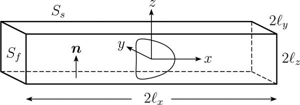
An elastic capsule flowing at the centerline of a square microchannel.
Far from the capsule, the flow approaches the undisturbed flow in a channel which is given in pages 309−312 in Ref.[23], i.e.
| (1) |
where
| (2) |
while p is the dynamic pressure. By integrating over the channel's cross-section, we can easily show that the volumetric flow rate Q is given by
| (3) |
The average velocity far from the capsule is while the maximum undisturbed velocity at the centerline of the square channel is . In our computations, we truncated the infinite (convergent) series associated with the channel's undisturbed flow when m = 40.
Assuming low-Reynolds-number flows, the governing equations in fluid 2 are the Stokes equations and continuity,
| (4) |
where σ is the stress tensor and u the fluid velocity. Inside the capsule, the same equations apply with the viscosity replaced by λμ. It is of interest to note that in small length-scale systems, such as microfluidic channels, low-Reynolds-number flows are easily achievable [11, 12]. (For example, in a microfluidic channel with size ℓy = 100 μm, the Reynolds number remains Re = O(10−3) even for velocities up to when we consider the density and viscosity of water.)
For the current problem, the system surface SB consists of the capsule interface Sc, the channel's solid surface Ss, and the fluid surface Sf of the channel's inlet and outlet far from the capsule. At the capsule's interface, the velocity is continuous and we define the surface stress vector (or hydrostatic traction) Δf from the stress tensor σ and the surface unit normal n, i.e.
| (5) |
Here the subscripts designate quantities evaluated in fluids 1 and 2, respectively, while n is the unit normal which we choose to point into fluid 2. The boundary conditions on the rest surfaces are
| (6) |
| (7) |
where f∞ is the force associated with the undisturbed channel flow u∞ far from the capsule.
Based on standard boundary integral formulation, the velocity at a point x0 on the system surface SB may be expressed as a surface integral of the force vector f = n · σ and the velocity u over all points x on the boundary SB,
| (8) |
where the coefficient Ω takes values 4πμ(1 + λ) and 4πμ for points x0 on the surfaces Sc and Ss ∪ Sf respectively. The tensors S and T are the fundamental solutions for the velocity and stress for the three-dimensional Stokes equations, i.e. known functions of the system surface SB [1, 24, 25].
Owing to the no-slip condition at the interface, the time evolution of the material points of the membrane may be determined via the kinematic condition at the interface
| (9) |
To produce a closed system of equations, the surface stress Δf on the capsule interface is determined by the membrane dynamics. Our membrane description is based on the well-established continuum approach and the theory of thin shells as described in detail in section 2.2 of our earlier publication [25]. We emphasize that the thin-shell theory has proved to be an excellent description of the membrane for a wide range of artificial capsules and for red blood cells, where the membrane thickness is several orders of magnitude smaller than the size of the capsule/cell [1, 25, 26].
For a membrane with shearing and area-dilation resistance considered in this work, the surface stress is determined by the in-plane stresses, i.e. Δf = −▽s ·τ which in contravariant form gives
| (10) |
where the Greek indices range over 1 and 2, while Einstein notation is employed for (every two) repeated indices. In this equation, the ταβ|α notation denotes covariant differentiation, tβ = ∂x/∂θβ are the tangent vectors on the capsule surface described with arbitrary curvilinear coordinates θβ, and bαβ is the surface curvature tensor [1, 25, 26]. The in-plane stress tensor τ is described by constitutive laws that depend on the material composition of the membrane. In this work, we employ the Skalak et al. law [16] which relates τ's eigenvalues (or principal elastic tensions , β = 1, 2) with the principal stretch ratios λβ by
| (11) |
(To calculate , reverse the λβ subscripts.) In the equation above, Gs is the membrane's shearing modulus while the dimensionless parameter C is associated with the area-dilatation modulus K of the membrane (scaled with its shearing modulus). It is of interest to note that the Skalak et al. law is a general constitutive equation able to describe strain-hardening membranes with any area-dilatation resistance, e.g. [1, 25, 26].
We further consider that the capsule is subjected to a positive osmotic pressure difference between the interior and exterior fluids, i.e. the capsule is (slightly) over-inflated and thus prestressed. Such consideration is motivated by the fact that, owing to osmotic effects during their fabrication, artificial capsules are often slightly over-inflated as the bioartificial capsules used in the experimental investigation of Risso, Collé-Pailot and Zagzoule [14]. In addition, incorporation of prestress into our elastic membrane model removes the buckling instability observed in axisymmetric-like flows. (See section 6 in Ref.[26].)
Following Lefebvre and Barthès-Biesel [15], we define the prestress parameter αp such that all lengths in the undeformed capsule would be scaled by (1 + αp), relative to the reference shape. Note that this is mathematically equivalent to scaling the stretch ratios λβ, appearing in the constitutive law describing the membrane, by (1 + αp). Since the capsule is initially spherical, its membrane is initially prestressed by an isotropic elastic tension (t = 0) which depends on the employed constitutive law and its parameters but not on the capsule size. For example, for a Skalak capsule with C = 1 and αp = 0.05, the undisturbed capsule size a is 5% higher than that of the reference shape and the initial membrane tension owing to prestress is τ0/Gs ≈ 0.3401.
B. Definition of Geometric and Physical Variables
To describe the capsule deformation, we consider several geometric properties including the capsule's dimensions and profile curvatures; most of them have been used in previous studies for capsule motion in cylindrical tubes, e.g. [14, 15]. In particular, we determine the capsule projection lengths along the three axes, Lx, Ly and Lz (where Ly = Lz for this problem owing to symmetry) as the maximum distance in the x, y and z coordinates of the capsule surface. The projection length along the x-axis, Lx, is divided into two parts with respect to the capsule's volume centroid xc, i.e. the downstream projection length and the upstream length . Further we calculate the minimum distance (gap) h between the capsule surface and the solid walls. Note that we employ a Newton method to solve these optimization problems.
In addition, we calculate the curvature at the downstream and upstream edges of the capsule (i.e. its intersections with the x-axis). The curvatures are determined along the capsule's y = 0 profile (i.e. the cross-section of the capsule surface with the y = 0 plane) by employing our spectral discretization at the middle point of the downstream and upstream spectral elements. We also determine the maximum curvature along the capsule's y = 0 profile; to do this, from the actual spectral grid we interpolate spectrally to a dense grid with NB = 15 basis points and find the higher value of the curvature among these spectral discretization points along the desired capsule's y = 0 profile.
In this study, we assume that the flow rate Q (or the average undisturbed velocity ) inside the channel is fixed. Thus we apply velocity boundary conditions at the channel's inlet and outlet (see Eq.(5)) and we solve for the fluid force at the channel ends. The fluid pressure at the channel's inlet and outlet, Pin and Pout, is determined as the surface-average of the normal force on these two surfaces
| (12) |
(Note that although we have chosen this way to determine the pressure at the channel ends, our computational results show that the fluid normal force, or pressure, at each channel end is constant to at least 4 significant digits among the spectral discretization points.) The pressure difference at the channel ends is ΔP = Pin − Pout and we also calculate the additional pressure difference owing to the presence of the capsule in the channel,
| (13) |
where ΔPnc is the pressure difference at the channel ends when no capsule is present in the channel. As the capsule moves in the channel, its volume-average velocity is determine from surface properties, i.e.
| (14) |
Our membrane description involves two moduli, one for shearing and one for area dilatation. The parameter C that stands for area dilatation is already dimensionless. The shearing modulus Gs introduces the (elastic) capillary number (i.e. a ratio of viscous flow forces to resistive elastic forces on the membrane) defined in this paper as
| (15) |
It is of interest to note that the capillary number, as defined by Eq.(15), does not contain any length scale, and thus it may be considered as a dimensionless flow rate. For a fixed capsule size a, varying the capillary number Ca can easily be achieved in an experimental system by keeping the exterior-fluid viscosity fixed and varying the flow rate, or average velocity . For a fixed capillary number Ca, varying the capsule size a can be achieved by using different volumes of capsules from the same membrane (and with the same prestress level).
In this study, if no scale is present, the channel's half-height ℓz is used as the length scale, the velocity is scaled with the average undisturbed velocity , and thus time is scaled with . In addition, the pressure is scaled with and the membrane tensions with Gs.
C. Membrane Spectral Boundary Element Algorithm
The numerical solution of the boundary integral equation, (8), is achieved through our spectral boundary element method for membranes [25]. Briefly, each boundary is divided into a moderate number NE of surface elements which are parameterized by two variables ξ and η on the square interval [−1, 1]2. The geometry and physical variables are discretized using Lagrangian interpolation in terms of these parametric variables. The NB basis points (ξi, ηi) for the interpolation are chosen as the zeros of orthogonal polynomials of Gauss-type. This is equivalent to an orthogonal polynomial expansion and yields the spectral convergence associated with such expansions.
The boundary integral equation (8) admits two different types of points. The collocation points x0 where the equation is required to hold and the basis points x where the physical variables u and f are specified or determined. Our spectral boundary element method employs collocation points x0 of Legendre–Gauss quadrature, i.e. in the interior of the elements. As a result the boundary integral equation holds even for singular elements, i.e. the elements which contain the corners of the channel geometry. (Similar approach has been utilized in our earlier papers for droplets attached to solid surfaces, and vascular endothelial cells or leukocytes adhering to the surface of blood vessels, e.g. [24, 27, 28].) In addition, we use basis points x of Legendre–Gauss–Lobatto quadrature and thus the physical variables are determined in the interior and on the edges of the spectral elements. For the time integration, we employed the 2nd-order Runge-Kutta scheme with a typical time step Δt = 0.5 × 10⁻³. Further details on our spectral boundary element algorithms are given in our earlier publications, i.e. [25, 29, 30].
Three-dimensional views of the problem geometry are shown in figure 2. In the present paper, the majority of computations were performed with a discretization employing NE = 36 elements. The capsule surface, by being projected onto a cube, is divided into a total of 6 elements as shown in figure 2 (a). The spectral element discretization of the channel surface follows the capsule's center of mass. The channel surface in the capsule vicinity is divided into a row of one spectral element per channel side (i.e. a total of four elements) with half-size equal to ℓz. The (rest) upstream and downstream channel surface is divided into three rows of four elements each; the length of each row progressively increases with the distance from the capsule as seen in figure 2 (b,c). In our computations, the channel surface (which formally should extend to infinity) has a half-length ℓx equal to 20 times the cross-section's half-length ℓz; this channel length is sufficient to produce negligible error in all cases. Finally the channel's inlet and outlet are discretized into one element each as shown in figure 2 (b).
FIG. 2.
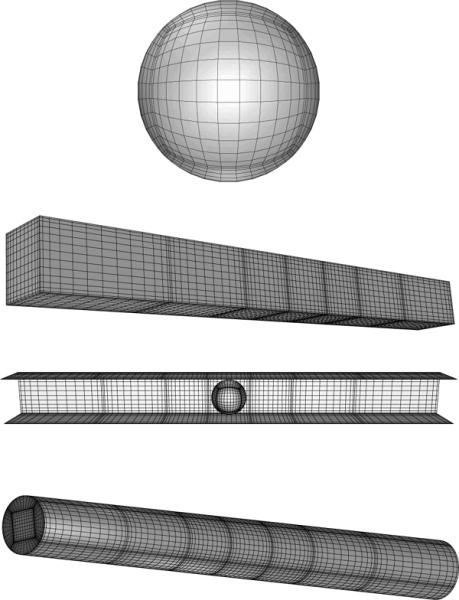
Spectral boundary element discretization of system surface: (a) capsule surface, (b) solid surface of a square channel along with the fluid surface at the channel end, (c) top view of the entire geometry after removing the channel's top side, and (d) solid surface of a cylindrical tube along with the fluid surface at the channel end. Each figure illustrates Lobatto distribution of nodal lines for the corresponding geometry with basis points NB = 14.
We note that our spectral boundary element algorithm has the ability to utilize more complicated surface element divisions, i.e. to use more elements on the capsule interface and more than one elements per row for each channel side. Such discretizations are not needed for the current problem since our convergence runs have shown that our employed element discretization produces a sufficient accuracy even in the most challenging cases studied here.
In our work we mostly utilized NB = 12–14 basis points i.e. a total number of spectral points for the entire geometry N = NE . To verify the accuracy of our results, we performed convergence runs covering the entire interfacial evolution (i.e. well past steady state) with NB = 10–16 basis points for all moderate and high capsule sizes we studied (i.e. 0.8 ≤ a ≤ 1.3) and for several smaller capsule sizes (i.e. 0.1 ≤ a ≤ 0.7). Our convergence runs showed that our results for the interfacial shape are accurate to at least 3 significant digits except for the most challenging cases studied in this work (i.e. largest capsules) where the interfacial shape was determined with an accuracy of at least 2 significant digits. In particular, in section 3, where we investigate moderate capsules (a = 0.6, 0.7, 0.8) for capillary number Ca = 0.1–0.5, the interfacial shape was determined with an accuracy of at least 3 significant digits in all cases. In section 4, where we investigate small and large capsules for a fixed capillary number (Ca = 0.1), the interfacial shape was determined with an accuracy of at least 3 significant digits for sizes a ≤ 1.25, while the interfacial shape of the largest capsule studied (a = 1.3) was determined with a maximum relative error of 3 × 10⁻³. The capsule velocity Ux and the additional pressure difference ΔP+ are always accurate to at least 3 significant digits.
In addition, we have compared our results with published results for capsule motion in cylindrical tubes [15]. To do this, we used our three-dimensional membrane algorithm and determine the capsule motion along the centerline of a cylindrical tube. (The spectral element discretization of the tube surface is shown in figure 2 (d)). All comparisons have shown that our results are in very good agreement with earlier results from axisymmetric methodologies. For example, in tube flow and for a Skalak capsule with size a = 0.8, prestress αp = 0.025 and capillary number Ca = 0.2, we found Lx = 1.68 and Lz = 1.52, while for a = 0.9, αp = 0.1 and Ca = 0.24 we found Lx = 2.03 and Lz = 1.60; both results are in very good agreement with the results of Lefebvre and Barthès-Biesel [15] shown in their figures 4 and 7. The capsule profiles were also in very good agreement as we verified via figure superposition. Lefebvre and Barthès-Biesel also reported in their table 1 that, for prestress αp = 0.05 and capsule size a = 0.8, the rear curvature changes sign when Ca = 0.1; we also found the same as shown in our figure 6.
FIG. 4.
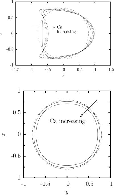
Steady-state capsule profile as a function of the capillary number Ca for a Skalak capsule with C = 1, αp = 0.05 and size a = 0.8 in a square microchannel. (a) Capsule y = 0 profile (i.e. interface intersection with the plane x = 0) for Ca = 0, 0.1, 0.2, 0.3, 0.4, 0.5. (b) Capsule x = 0 profile for Ca = 0, 0.1, 0.5. All profiles are shown with centroid xc = 0.
FIG. 7.
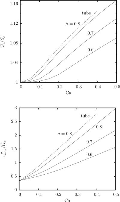
Steady-state capsule properties as a function of the capillary number Ca for a Skalak capsule with C = 1, αp = 0.05 and size a = 0.6, 0.7, 0.8 in a square microchannel. (a) Surface area of the capsule Sc at steady state (scaled with the surface area of the undisturbed spherical shape). (b) Maximum principal tension among the spectral discretization points on the membrane. Also included are the corresponding results for a capsule with size a = 0.8 in a cylindrical tube (– – –).
TABLE 1.
Scaling laws with respect to capsule size a for a Skalak capsule with C = 1, αp = 0.05 and capillary number Ca = 0.1 in a square channel and a cylindrical tube at steady state. SDC is the curvature at the downstream edge scaled with the curvature a−1 of the undisturbed spherical shape. (Similar scaling for small capsule sizes we also found for the scaled downstream and maximum curvatures.) The length scale Ls is the channel's half-height ℓz or the tube radius R and the pressure scale is .
| Square Channel | Cylindrical Tube | ||||
|---|---|---|---|---|---|
|
| |||||
| Property | Small size a | Large size a | Small size a | Large size a | |
|
| |||||
| Lx − Lz/2 | a | 1.25 a3 | a | 1.50 a3 | |
| Lz/2 = 1 − h | a | a | |||
| h | 0.13 a−2 | 0.15 a−2 | |||
|
|
0.015 a4 | 0.019 a4 | |||
| SDC − 1 | 0.73 a2 | 0.47 a3/4 | 0.80 a2 | 0.50 a3/4 | |
|
|
(3.5/3) a2 | (4.0/3) a2 | |||
|
|
0.27 a−2 | 0.20 a−2 | |||
| ΔP+/Π | 9.5 a5 | ≈ 9.5 a5 | 16 a5 | ≈ 16 a5 | |
|
|
0.42 a2 | 0.95 a4 | 0.50 a2 | 1.30 a4 | |
FIG. 6.
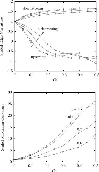
Steady-state capsule curvatures as a function of the capillary number Ca for a Skalak capsule with C = 1 and αp = 0.05 in a square microchannel. (a) Curvature at the downstream and upstream edges of the capsule (i.e. its intersections with the x-axis). The curvatures are determined along capsule's y = 0 profile (i.e. the cross-section of the capsule surface with the y = 0 plane). (b) Maximum curvature along the capsule's y = 0 profile. All curvatures are scaled with the curvature of the undisturbed spherical shape. Capsules sizes a: ⋄, 0.6; ∘, 0.7; ◻, 0.8. Also included are the corresponding results for a capsule with size a = 0.8 in a cylindrical tube (– – –).
The problem studied in this paper admits three independent symmetry planes, y = 0, z = 0 and y = z. Exploiting these symmetries reduces the memory requirements for the storage of the system matrices by a factor of 82, the computational time for calculating the system matrices by a factor of 8 and the solution time of the linear systems via direct solvers by a factor of 83. Most of our computations were performed on quad-core computers utilizing the existing parallelization of our spectral boundary element algorithm via OpenMP directives for the calculation of the system matrices, and highly optimized, parallelized routines from the LAPACK library for the solution of the dense system matrices.
3. EFFECTS OF THE CAPILLARY NUMBER ON THE STEADY-STATE PROPERTIES OF MODERATE-SIZE CAPSULES
In this section we collect our steady-state results on the geometric and physical variables of interest, described earlier in section 2 B, as a function of the flow rate for moderatesize capsules. In particular, we consider Skalak capsules with prestress αp = 0.05 and size a = 0.6, 0.7, 0.8 (i.e. smaller than the channel size ℓz) and capillary number Ca in the range [0, 0.5] (i.e. small and moderate flow rates). To obtain these steady-state results we initiate our computations from a spherical capsule at the channel centerline using viscosity ratio λ = 1 and compute the capsule dynamics until times t = 10–20, i.e. well-past steady state which usually is achieved around time t = 2–4. Although the transient evolution is affected by the viscosity ratio, at steady state there is no flow inside the capsule and thus the steady-state capsule properties are independent of the inner viscosity. For the same reason, the membrane viscosity (if any), which is not accounted in our computations, does not affect the capsule's steady-state properties.
Figure 3(a) shows the effects of the capillary number on the steady-state capsule dimensions for the three capsule sizes studied in this section. The capsule length Lx/(2a) first decreases with the flow rate and then increases. For the three capsules studied here, only the largest capsule with a = 0.8 achieves eventually a length greater than its undisturbed size. On the other hand, the behavior of the capsule height Lz depends on the capsule size. The two smaller capsules with a = 0.6, 0.7 increase slightly their height Lz/(2a) as the flow rate increases, however for a = 0.8 the capsule height Lz/(2a) is decreased with the flow rate. This behavior can be attributed to the non-monotonic behavior of the capsule length Lx owing to the preservation of the capsule volume.
FIG. 3.
Steady-state capsule lengths as a function of the capillary number Ca for a Skalak capsule with C = 1 and αp = 0.05 in a square microchannel. (a) Capsule lengths Lx/(2a) and Lz/(2a). (b) Capsule lengths and . Capsules sizes a: ◇, 0.6; ∘, 0.7; ◻, 0.8.
Dividing the capsule length Lx into its downstream and upstream parts (based on the capsule centroid), figure 3(b) shows that the capsule's downstream length shows a monotonic increase with the flow rate and the capsule size. In addition, the capsule upstream length first decreases with the flow rate and then increases. Therefore, figure 3(b) suggests that the capsule's flow dynamics can be divided into two parts: the downstream dynamics where a monotonic dependence (e.g. length increase) is found with the flow rate, and the upstream part which is characterized by a more complicated flow dynamics and which may a ect the entire capsule shape.
The effects of the capillary number on the downstream and upstream lengths of the capsule, and , can also be seen in the y = 0 profiles of a capsule with size a = 0.8 presented in figure 4(a) since all these profiles have the same centroid xc = 0. The monotonic increase of with the flow rate results from the relatively extension of the downstream tip of the capsule. On the other hand, the late flow-rate increase of the upstream length results form the development of a pointed tail at the capsule rear close to the solid walls. Looking at the capsule x = 0 profiles (i.e. perpendicular to the flow direction) presented in figure 4(b), we observe that even for the largest capsule (size a = 0.8) and at the highest flow rate (Ca = 0.5) studied in this section, the capsule remains almost axisymmetric.
For a better view of the three-dimensional capsule shape, in figure 5 we present the steady-state capsule shape for size a = 0.8 and for capillary number Ca = 0.1, 0.5. For each case, we plot the shape perpendicular to the flow direction inside the channel and askew from the flow direction. Note that the three-dimensional views of the capsule shape presented in this paper were derived from the actual spectral grid by spectrally interpolating to NB = 25 and using orthographic projection in plotting.
FIG. 5.
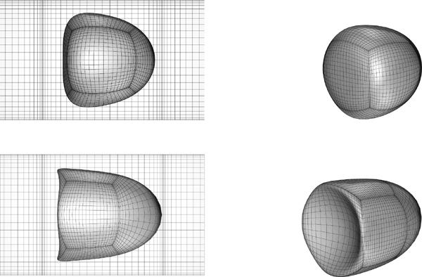
Steady-state shape of a Skalak capsule with C = 1, αp = 0.05 and size a = 0.8 in a square microchannel. Capillary number: (a) Ca = 0.1, and (b) Ca = 0.5.
Figure 6 shows the effects of the flow rate Ca on the steady-state curvatures along the capsule's y = 0 profile. As the flow rate increases, the capsule downstream edge becomes more pointed while the scaled curvature there increases slightly with the capsule size. At the same time, the capsule tends to decrease the curvature at its upstream edge from a concave shape at small Ca towards a flat edge and then a convex edge (with negative curvature) as the flow rate increases. (Both effects are also shown in the capsule y = 0 profiles presented in figure 4.) For the three capsule sizes studied here, the transition to a convex edge occurs around 0.1 ≤ Ca ≤ 0.2 and happens at a smaller flow rate as the capsule size increases. After a slow increase at very small flow rates, the maximum curvature along the capsule's y = 0 profile increases linearly with the capillary number as seen in figure 6(b). The scaled maximum curvature also increases with the capsule size. Thus the capsule develops very pointed tails at its upstream section characterized by a local length scale (or radius of curvature) which is of O(10) (or more) smaller than the capsule size for the maximum flow rate, Ca = 0.5, studied here.
Considering the variation of the capsule surface area Sc with the flow rate (which can be regarded as an index of the entire capsule deformation), figure 7(a) shows that after an initial slow increase at small flow rates, the steady-state surface area Sc increases linearly with the capillary number while capsules with larger size a show a higher surface area increase. The same pattern is valid for the maximum principal tension on the membrane as seen in figure 7(b). It is interesting to note that the maximum tension at steady state is always located at the downstream element of the capsule, along the y = 0 (or z = 0) profile and between the capsule downstream tip and the element end. Therefore this location is the most probable to rupture when a capsule flows in a microchannel.
Figure 8 shows the steady-state variation (with the flow rate) of the volume-average capsule velocity Ux and the additional pressure difference ΔP+ as well as the minimum distance h between the capsule surface and the channel's walls. All these variables are not affected much by the capillary number for each of the three capsule sizes included in this figure. As the capsule size a increases, the smaller distance h between the capsule surface and the walls results in a slower capsule motion and in higher pressure drop.
FIG. 8.
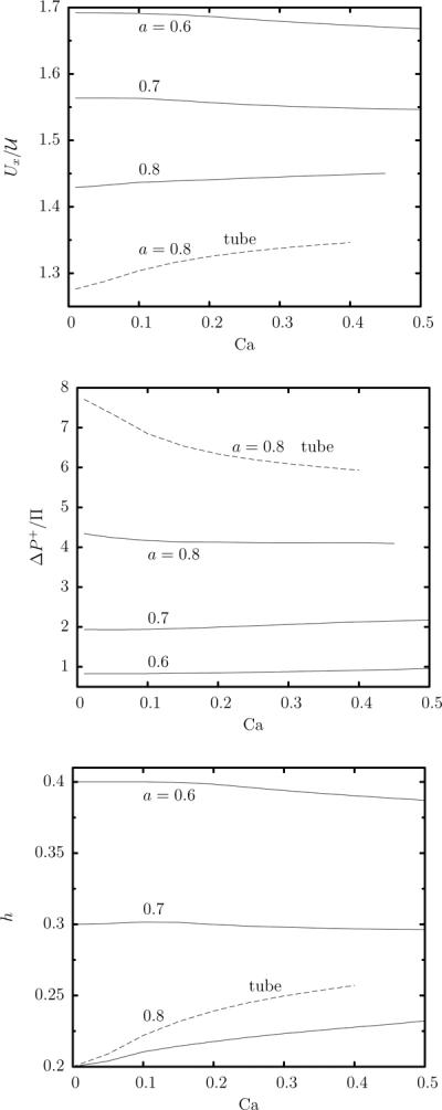
Steady-state capsule properties as a function of the capillary number Ca for a Skalak capsule with C = 1, αp = 0.05 and size a = 0.6, 0.7, 0.8 in a square microchannel. (a) Capsule velocity Ux. (b) Additional pressure difference ΔP+. (c) Minimum distance h between the capsule surface and the channel's walls. Also included are the corresponding results for a capsule with size a = 0.8 in a cylindrical tube (– – –).
A. Comparison with flow in a cylindrical tube
Owing to their nearly axisymmetric cross-section in the flow direction shown in figure 4(b), small and moderate capsules in square channels should show dynamics similar to that in cylindrical tubes. In particular, similar (qualitative) behavior for the capsule's length Lx, height Lz, and downstream and upstream curvatures were found in earlier experimental and computational studies, e.g. [13–15]. For example, see figure 4 in the work by Lefebvre and Barthès-Biesel [15] who considered the steady-state properties of capsules with prestress αp = 0, 0.025, 0.1 and size a/R = 0.8 (where R is the tube radius). We note that figure 11 of the earlier study shows that in cylindrical tubes the pressure drop increases (almost) linearly with the capillary number Ca; this appears to contrast with our results presented in figure 8(b). This difference results from the different scales used for the pressure; in particular, the earlier study scaled the pressure based on membrane properties (i.e. Gs/R) while we scale the pressure based on flow properties (i.e. ). Scaling the pressure as in our study, the results of Lefebvre and Barthès-Biesel [15] presented in their figure 11 show that the pressure drop is rather insensitive to the capillary number for moderate-size capsules as also found in our study.
FIG. 11.
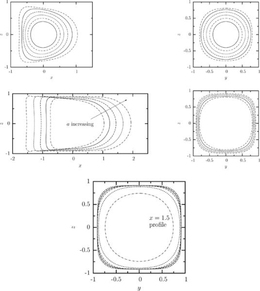
Steady-state profile of a Skalak capsule with C = 1, αp = 0.05 and capillary number Ca = 0.1 in a square channel. (a) Capsule y = 0 profile (i.e. interface intersection with the plane x = 0) for size a = 0.4, 0.5, 0.6, 0.7, 0.8, 0.9. (b) As in (a) but for x = 0 profile. (c) Capsule y = 0 profile for size a = 0.9, 1, 1.1, 1.2, 1.3. (d As in (c) but for x = 0 profile. (e) Interface intersection with the planes x = −1, −0.5, 0, 0.5, 1, 1.5 for size a = 1.3. All profiles are shown with centroid xc = 0.
The similarity of the channel and tube dynamics at moderate capsule sizes motivated us to make detailed comparisons of the two cases to identify clearly their similarities and differences. Since the earlier computational studies which considered capsule dynamics in cylindrical tubes [13, 15] did not report results for the prestress level used in this paper, we studied this problem for prestress αp = 0.05, capsule size a = 0.8 and several flow rates using our (three-dimensional) membrane algorithm. The spectral boundary element discretization of the tube wall was identical to that for the channel (i.e. we defined rows of four elements) while the tube's inlet and outlet were discretized into five elements each as shown in figure 2 (d). For this system, the tube radius R is used as the length scale while all rest parameters are defined as for the channel problem reported in section 2 B. Considering the dynamics of a capsule in both solid ducts at a given capillary number Ca means that we apply the same average duct velocity as seen in Eq.(15).
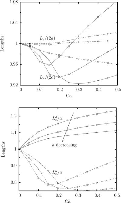
Figure 9 shows the variation of the capsule lengths in channel and tube flow. In the channel, the capsule is less deformed (i.e. it is less extended along the flow direction and more extended laterally), for the same capillary number Ca, than in the tube. The smaller interfacial deformation in the channel results from the existence of the corners area which permits flow of the surrounding fluid and thus causes less deformation on the capsule. In a similar manner, the capsule in the tube shows larger downstream and upstream lengths, and , than in the channel. Excluding small capillary numbers (e.g. Ca ≤ 0.1), figure 9 shows that a capsule in a channel at a given capillary number has the same dimensions as in a tube flow but at a much lower capillary number. For example, the capsule lengths in the flow direction, Lx, and , are very similar for channel flow with Ca = 0.35 and tube flow with Ca = 0.2. The capsule height Lz in a channel with Ca = 0.35 corresponds to near Ca = 0.13 in a tube.
FIG. 9.
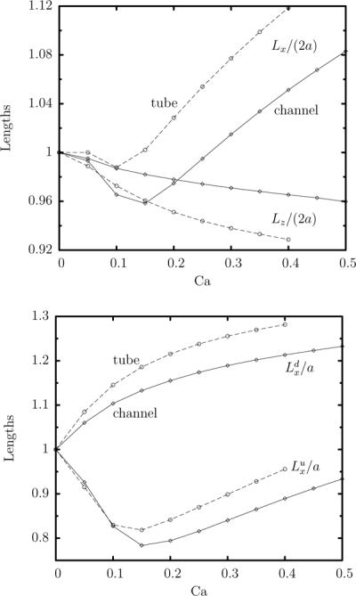
Steady-state capsule lengths as a function of the capillary number Ca for a Skalak capsule with C = 1, αp = 0.05 and size a = 0.8, in a square channel ( ) and a cylindrical tube (– – –). (a) Capsule lengths Lx/(2a) and Lz/(2a). (b) Capsule lengths and .
In contrast to the different interfacial deformation in channels and tubes, the capsule curvatures are very similar in these two system, as seen in figure 6. Thus, for capsules flowing in these two solid geometries, the interfacial curvatures are mostly determined by the capsule size and the capillary number, and not by the details of the cross-section of the solid geometry. It is of interest to note that, excluding small capillary numbers, our results show that the curvature at the downstream and upstream edges are rather insensitive to the capillary number for both solid systems (i.e. they are practically constant at moderate flow rates). On the other hand, the maximum profile curvature which occurs at the capsule rear end and close to the walls, increases fast with the capillary number as seen in figure 6(b).
The higher interfacial deformation in the tube flow results in a higher surface-area increase for the capsule and higher membrane tensions as seen in figure 7. However, now the correspondence in Ca for the two solid geometries are not as different as for the capsule lengths; for instance, very similar maximum principal tensions are obtained for Ca = 0.35 in the channel and Ca = 0.3 in the tube. The higher interfacial deformation in the tube flow also results in a higher gap between the capsule and the walls as shown in figure 8(c). However, the existence of the corners area in the channel means that in this system the capsule blocks less the flow of the surrounding fluid. Thus in a tube the same capsule causes a much higher pressure drop and travels with a smaller velocity than in a channel as seen in figure 8(a, b).
4. EFFECTS OF THE CAPSULE SIZE ON THE STEADY-STATE PROPERTIES
In this section we collect our steady-state results on the geometric and physical variables of interest, described earlier in section 2 B, as a function of the capsule size a for channel flow with capillary number Ca = 0.1. In particular, we consider Skalak capsules with prestress αp = 0.05 and size a = 0.1, 0.2, …, 1.3, i.e. both smaller and larger than the channel height ℓz. To obtain these steady-state results, for capsules with size a < 1 we initiated our computations from a spherical capsule at the channel centerline and computed the capsule dynamics for viscosity ratio λ = 1 until times t = 10–20, i.e. well-past steady state. For capsules with size a ≥ 1, we did the same but we initiated our computations from an ellipsoidal capsule with width near 0.95 and appropriate length (greater than unity) to account for the specific capsule volume.
To facilitate the comparison of the channel flow with that in a cylindrical tube, we include our results for tube motion in several figures in this section. However our discussion on these comparisons are presented at this end of this section. It is of interest to note that as the capsule size a increases, negative tensions appear near steady state and cause numerical instability, i.e. the specific prestress used in our study (αp = 0.05) is not adequate to enforce positive membrane tensions at sufficiently large capsules. (The buckling instability for axisymmetric-like flows is discussed in section 6 in Ref.[26].) Thus for this prestress we are unable to determine stable steady-state shapes for size a ≥ 1.4 for channel flow and a ≥ 1.2 for tube flow.
Figure 10(a) shows the effects of the capsule size a on the steady-state capsule dimensions. Note that we prefer not to scale the capsule lengths with the capsule size a since for large capsules such scaling is not appropriate for properties associated with the capsule height. The capsule length Lx shows a monotonic increase with a while its height Lz, after an initial fast increase, slows down as it reaches the channel height. It is of interest to note that both dimensions increase identically until size a ≈ 0.9 and then their behavior diverges. For higher capsule sizes, as the capsule height Lz is restricted by the channel height, the capsule length Lx increases faster to accommodate the capsule's larger volume. Considering the downstream and upstream parts of the capsule length in figure 10(b), we see that after an initial common increase, the upstream length increases slower for sizes , and then shows a fast increase similar to that of the downstream length .
FIG. 10.
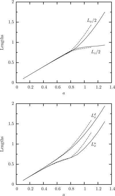
Steady-state capsule lengths as a function of the capsule's size a for a Skalak capsule with C = 1, αp = 0.05 and capillary number Ca = 0.1, in a square channel ( ) and a cylindrical tube (– – –). (a) Capsule lengths Lx/2 and Lz/2. (b) Capsule lengths and .
To explain the behavior of the upstream length , it is beneficial to see the steady-state y = 0 profiles of small and large capsules plotted in figure 11(a, c). For small capsule sizes , the hydrodynamic forces associated with the flow rate Ca = 0.1 are weak and cause minimal deformation; thus the capsule is nearly spherical. For moderate capsule sizes , the length Lx and the height Lz are practically equal to their undisturbed value 2a. However, now the hydrodynamic forces are stronger owing to the smaller gap between the capsule interface and the solid walls, and cause the capsule to deform into a shape with a pointed downstream edge and a flattened rear. Because of this interfacial deformation, the capsule centroid is shifted to the back, i.e. its upstream length decreases with respect to its downstream length . For size a ≈ 0.9, the capsule height Lz has reached the channel's height and further increase is limited owing to the strong hydrodynamic forces in the narrow gap between the capsule surface and the wall. The capsule obtains a bullet-like shape and further increase in its size results mainly in a length increase, and thus increase of both downstream and upstream parts of the capsule length.
Looking at the x = 0 profile of the different capsules included in figure 11(b, d), we observe that the capsule remains axisymmetric until a ≈ 0.8. At higher sizes, the capsule's x = 0 profile becomes a square with rounded corners, especially for the larger capsules, as seen in figure 11(d). Thus, the capsule interface becomes parallel to the channels walls and rounded at the channel's corners. This development clearly suggests that for capillary number Ca = 0.1, the capsule shape becomes non-axisymmetric (i.e. fully three-dimensional) for capsule sizes a ≥ 0.9.
It is of interest to note that this non-axisymmetric interfacial deformation is associated mainly with the capsule's upstream portion (i.e. from its centroid to its rear end), and not with its downstream portion which remains axisymmetric. To show this, in figure 11(e) we plot the capsule's interface intersection with different x-planes (with respect to the capsule centroid). The profiles at x = 1, 1.5 are circular and thus the downstream portion of the capsule is like a cylinder with an end spherical cap.
Looking at the capsule's x = 0 profiles shown in figure 11 as well as in figure 4 from the previous section, we note that when the hydrodynamic forces on the capsule are increased (i.e. by increasing the flow rate for a given capsule or by increasing the capsule size for a given flow rate), the capsule develops a pointed downstream edge and a flattened rear (possibly with a negative curvature). This is similar to the deformation of droplets which try to increase the downstream curvature and decrease the upstream curvature so that they increase the restoring (surface) tension force [3, 12]. Therefore this capsule deformation results from the curvature term in the membrane traction, Eq.(10), as we identified for the high-curvature tips of elastic capsules in strong planar extensional flows in our earlier studies [25, 31]. We emphasize that in the present study, the membrane tensions at steady state are always positive owing to prestress and thus negative curvature or dimples on the capsule interface cannot result from local negative tensions.
The three-dimensional shapes of two large capsules with size a = 1.1, 1.3 are shown in figure 12. Beyond the dimple with negative curvature which occurs at the capsule's rear end, we also observe the development of dimples at the capsule lateral surface and near its rear, at each side of the channel. This lateral dimple is also shown in the capsule profiles in figure 11(d). Similar lateral dimples can be seen in the experimental photos (i.e. capsule profiles) of large capsules moving in square microfluidic channels in the recent work of Lefebvre et al. [9]. (See figures 10 and 11 in the earlier study.) In addition, lateral dimples have also been found on large capsules moving in cylindrical tubes, in experimental and computational studies, although in this case the dimple is, obviously, axisymmetric [13, 14].
FIG. 12.
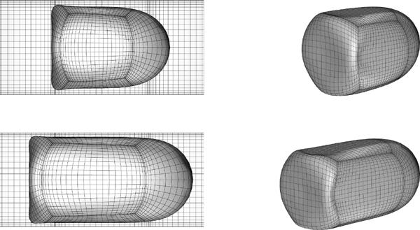
Steady-state shape of a Skalak capsule with C = 1, αp = 0.05 and capillary number Ca = 0.1 in a square channel. Capsule's size: (a) a = 1.1, and (b) a = 1.3.
Figure 13(a) shows the effects of the capsule size on the steady-state scaled curvature at the downstream and upstream edges of the capsule (i.e. its intersections with the x-axis). Note that the curvatures are scaled with the curvature of the undisturbed spherical shape, and thus this figure is more suited for the capsules with size smaller than the channel's height. This plot shows that even at small sizes a ≤ 0.4, the capsule downstream edge becomes more pointed while the opposite happens at its upstream edge. (Note that these curvature variations cannot be easily observed in the capsule profiles shown in figure 11(a).) For moderate capsule sizes 0.4 ≤ a ≤ 0.9, the significant capsule deformation shown earlier in figure 11(a) is associated with a faster increase of the curvature at the downstream edge and a faster decrease of the curvature at the upstream edge. Thus the downstream edge becomes more pointed (relatively to the undisturbed spherical shape) while the upstream edge flattens as seen in the profiles of figure 11(a). Note that a dimple with negative curvature has been developed at the rear end of the capsule with size a = 0.9.
FIG. 13.
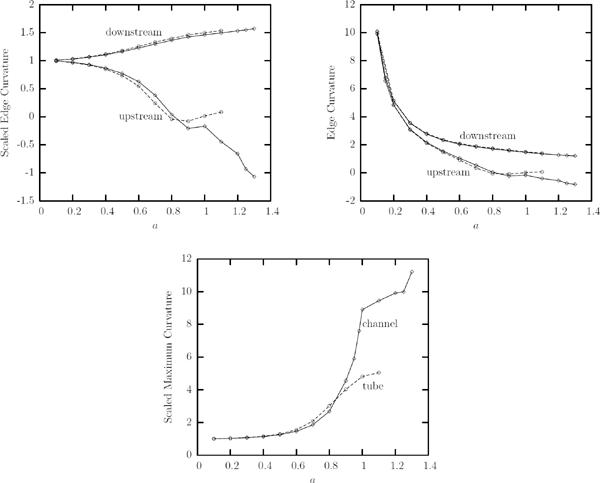
Steady-state capsule curvatures as a function of the capsule's size a for a Skalak capsule with C = 1, αp = 0.05 and capillary number Ca = 0.1, in a square channel ( ) and a cylindrical tube (– – –). (a) Scaled curvature at the downstream and upstream edges of the capsule (i.e. its intersections with the x-axis). The curvatures are determined along capsule's y = 0 profile (i.e. the cross-section of the capsule surface with the y = 0 plane). (b) As in (a) but for unscaled curvatures. (c) Maximum scaled curvature along the capsule's y = 0 profile. In (a) and (c) the curvatures are scaled with the curvature of the undisturbed spherical shape.
In figure 13(b) we present the variation with the capsule size of the (unscaled) curvature at the downstream and upstream edges of the capsule. Thus this figure is more suited for the larger capsules where the capsule covers almost the entire channel height. This plot shows that for large capsules, e.g. a ≥ 0.9, the curvature at the downstream edge decreases slightly only with the capsule size (i.e. it is practically independent of the size a). Similar is the variation of the curvature at the upstream edge which becomes slightly more negative with the capsule size.
Figure 13(c) shows the maximum curvature along the capsule's y = 0 profile (scaled with the curvature of the undisturbed spherical shape). This figure shows that the variation of the maximum profile curvature with the capsule size is divided into three distinct areas owing to the corresponding types of capsule profiles shown earlier in figure 11. In particular, for small sizes, , the maximum curvature occurs at the downstream edge of the nearly spherical capsules. For moderate sizes, , the maximum curvature increases fast with the size owing to the development of the tail at the capsule rear and close to the walls. Finally, for large sizes, , a further increase of the maximum curvature occurs owing to the development of the lateral dimple near the capsule rear. Thus, large capsules develop at their rear tail and close to the walls, pointed local areas characterized by a local length scale (or radius of curvature) which is of O(10) smaller than the capsule size, as we also found for moderate-size capsules at high flow rates in section 3.
We now turn our attention to properties associated with the entire capsule deformation, and in figure 14 we present the variation with the size a of the capsule's surface area Sc and the maximum principal tension on the membrane. After an initial slow increase at small capsule sizes, both properties increase fast with the capsule size for large capsules. Even for the large capsules studied in this section, the maximum tension at steady state is always located at the downstream element of the capsule, along the y = 0 (or z = 0) profile and between the capsule downstream tip and the element end. Therefore this location is the most probable to rupture when a capsule flows in a microchannel.
FIG. 14.
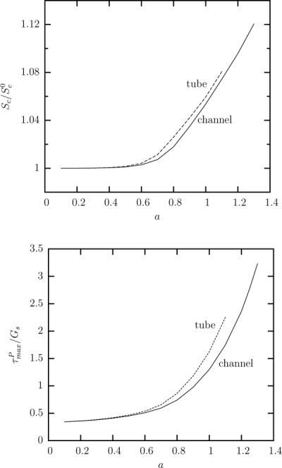
Steady-state capsule properties as a function of the capsule's size a for a Skalak capsule with C = 1, αp = 0.05 and capillary number Ca = 0.1, in a square channel ( ) and a cylindrical tube (– – –). (a) Surface area of the capsule at steady state Sc (scaled with the surface area of the undisturbed spherical shape). (b) Maximum principal tension among the spectral discretization points on the membrane.
Figure 15 shows the steady-state variation with the capsule size a of the volume-average capsule velocity Ux and the additional pressure difference ΔP+ as well as the minimum distance h between the capsule surface and the channel's walls. In contrast to the insensitivity of these variables with the flow rate Ca found in section 3, now we observe that the capsule velocity Ux decreases and the pressure drop ΔP+ increases significantly as the capsule size increases owing to the smaller gap h between the capsule surface and the walls. It is of interest to note that capsules, larger than the channel height, move with a velocity just higher than the channel's undisturbed average velocity and cause a very significant pressure drop in the channel.
FIG. 15.
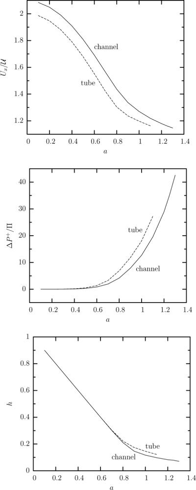
Steady-state capsule properties as a function of the capsule's size a for a Skalak capsule with C = 1, αp = 0.05 and capillary number Ca = 0.1, in a square channel ( ) and a cylindrical tube (– – –). (a) Capsule velocity Ux. (b) Additional pressure drop ΔP+. (c) Minimum distance h between the capsule surface and the channel's walls.
A. Comparison with flow in a cylindrical tube
Comparison between channel and tube flow with respect to capsule size reveals similar results to those with respect to flow rate presented in section 3 A. As shown in figure 10, the behavior of the capsule lengths in tube flow for increasing capsule size is similar to that in the channel. In the latter geometry, large capsules are less deformed, and thus less extended in the flow direction and more extended laterally, owing to the existence of the corners area which permits flow of the surrounding flow and thus causes less deformation on the capsule.
Figure 13(a, b) shows that the curvature at the downstream edge is practically the same for both solid systems. The same is true for the curvature at the upstream edge until sizes near a = 0.8; for higher capsule sizes, the upstream curvature is practically constant in tube flow but decreases into higher negative values in channel flow. This behavior in the tube is consistent with the results of Lefebvre and Barthès-Biesel [15] who showed at their table 1 that for capsule sizes a = 0.8, 0.9, 1 the upstream curvature is practically zero for a fixed capillary number and not very small prestress. (In particular for Ca = 0.1 when αp = 0.05 and Ca = 0.2 when αp = 0.1.)
The identical curvature evolution at the downstream edge in both solid systems can be understood since in both systems the downstream portion of the capsule remains axisymmetric as we show for the channel flow in figure 11(e). On the other hand, the different upstream curvature in the tube and channel at high enough capsule sizes can be attributed to the development of the (non-axisymmetric) rounded square cross-section of the upstream portion of the capsule for sizes a ≥ 0.9 as shown in figure 11(d). For the same reason, a large capsule in a tube flow does not show as high maximum profile curvature as in a channel (figure 13(c)).
The higher interfacial deformation in the tube flow for large capsules results in a higher surface-area increase and higher membrane tensions as seen in figure 14. Figure 15(a) shows that a capsule in a tube has always lower velocity than in a channel while this difference decreases at large capsule sizes. We note that in this figure the velocity is scaled with the average fluid velocity which is an appropriate scale mainly for large capsules. (As shown in this figure, small-size capsules travel with the maximum fluid velocity while large capsules travel with a velocity closer to the average fluid velocity.) Even when we scale our velocity findings with the maximum fluid velocity in each solid system (not shown), we observe that small- and moderate-size capsules travel slower in the tube. Owing to the existence of the corners area, a capsule in a channel causes less fluid blocking, and thus a smaller pressure drop compared to that in a tube, as shown in figure 15(b).
5. ANALYSIS AND SCALING LAWS
In this section, using our computational results for capsule motion in square channels and cylindrical tubes for capillary number Ca = 0.1 presented in section 4, we derive scaling laws with respect to the capsule size a for the geometric and physical variables we consider in our work. We note that most capsule's geometric and physical properties are also affected by the flow rate Ca as seen in section 3. Exceptions are the capsule velocity Ux and additional pressure difference ΔP+ for small and moderate-size capsules which are practically independent of the capillary number for the small and moderate flow rates studied in this work. In addition, based on basic physical principles and geometric properties, we develop a theoretical analysis that explains the power laws we found in this work.
It is of interest to note that very limited information is currently known with respect to the scaling-law behavior of capsules flowing in solid ducts. In particular, it appears that the only available information is two power laws for the additional pressure difference and capsule velocity as a function of the capillary number from the work of Quéguiner and Barthès-Biesel [13]. Using their axisymmetric results for a strain-softening neo-Hookean capsule in a cylindrical tube, the authors determined, via least-square fitting, the coefficients for ΔP+ = k1 Ca−n1 and that match best a given capsule size, for capsule sizes a/R = 0.8, 0.9, 1, 1.2, 1.4. We note that the four coefficients in these two power laws were found to vary with the capsule size, while a power-law behavior with respect to the capsule size was not identified.
The limited information on the scaling-law behavior of capsule motion in solid ducts is in contrast to the current knowledge from the corresponding problem of droplet motion in wall-bounded Stokes flows which has been studied rather extensively in the last four decades, e.g. [12, 20–22]. The viscosity ratio does affect the steady-state behavior of droplets, and different dynamics have been identified for low- and high-viscosity droplets. We note that capsule motion corresponds better to the dynamics of high-viscosity droplets since at steady state both a capsule and a high-viscosity droplet translate in the duct flow as a solid with zero inner velocity.
Table 1 presents the power laws (with respect to the capsule size a) we found for several steady-state geometric and physical properties of capsules flowing in square channels and cylindrical tubes. The corresponding figures that show these laws and the range of validity in capsule size are given in the paper's appendix. For both channel and tube flows, the table's column “small size a” represents small and moderate capsule sizes while the table's column “large size a” represents moderate and large capsule sizes up to the maximum capsule size studied in this work, i.e. a = 1.1 for tube flow and a = 1.3 for channel flow. Note that in the latter case, the associated scaling laws may also be valid for larger capsule sizes as supported by our analysis below.
Several conclusions can be drawn from table 1. For any capsule size, the scaling laws for channel flow are identical to those in tube flow except for the multiplication coefficient, even though in the channel the cross-section in the upstream portion of large capsules is non-axisymmetric, i.e. square-like with rounded corners, as shown in figures 11 and 12. The different multiplication coefficients in these two types of solid geometries are to be expected since for a given flow rate Ca, the same capsule in the channel is less deformed than in the tube owing to the existence of the corners area (gutters) which permits flow of the surrounding flow and thus causes less deformation on the capsule. Therefore in the tube the capsule shows a higher length Lx and smaller height Lz as well as a higher downstream curvature, surface area increase and membrane tensions. In addition, the corners gutters reduce significantly the excess pressure difference in the channel flow.
Furthermore, the existence of identical power laws for large capsules in channel and tube flows show that the parameter space studied in the present work does not represent squeezing capsule motion (i.e. large capsules at sufficient low flow rates so that the capsules travel very tightly inside the solid ducts) since in such case the channel flow should be governed by different laws (with respect to the tube flow) owing to the significant fluid flow at the corners gutters as found for droplet motion [12].
For small and moderate sizes, the capsule velocity Ux and additional pressure drop ΔP+ in tube flow are governed by exactly the same scaling laws as for high-viscosity droplets, i.e. the predictions of Hetsroni et al. [20] and Brenner [21]. In particular, Hetsroni et al. [20] determined analytically the velocity of a very small droplet moving along the centerline of a cylindrical capillary; their results for high viscosity ratio (i.e. λ → ∞) give
| (16) |
Brenner [21] provided the additional pressure drop for the same system; his results for high-viscosity droplets are
| (17) |
The identical scaling-law behavior of capsules and high-viscosity droplets in a tube flow supports clearly our earlier conclusion that the capsule steady-state motion in solid ducts corresponds better to the motion of high-viscosity (i.e. λ → ∞) droplets. It is interesting to note that the predictions of Hetsroni et al. [20] and Brenner [21] show that, for small and moderate droplet sizes, the velocity Ux and additional pressure difference ΔP+ are independent of the capillary number Ca, as we also found for small and moderate capsules in section 3.
For the large capsules studied in this work, the additional pressure difference ΔP+ follows the same scaling-law behavior as for small and moderate capsules. Furthermore, the velocity of large capsules approaches the average undisturbed duct velocity as as shown in table 1. As the capsule size increases, the maximum membrane tensions increase their dependence on the capsule size from at small and moderate sizes, to for large capsules.
By combining basic physical principles and geometric properties, we present now an analysis that explains the power laws we found for large capsules. Since for our study we found the same scaling laws for both tube and channel flows, our analysis is based mostly on the (simpler) tube flow. In our analysis, at first we accept as given the dependence of the lubrication film thickness h on the capsule size a from our computations, i.e. h/R = 0.15 (a/R)−2 for tube flow, and by employing this relationship, we derive the scaling laws we found for the additional pressure difference and the capsule velocity. Afterwards we propose a scaling analysis to justify the dependence of h on the capsule size a. To facilitate the notation, in some in-line equations the variables scales are omitted and thus the default scales are assumed as happens in our entire study (see end of section 2 B). For tube flow, the length scale Ls is the tube radius R and the pressure scale is .
To justify the power law for the capsule velocity found in our work for large capsules, we utilize the velocity at high-viscosity ratio (i.e. λ → ∞) of a long cylindrical droplet in a tube flow given by Eq.(4.5) in the paper by Lac and Sherwood [22], i.e.
| (18) |
where δ is the dimensionless half-width of the capsule, i.e. δR = Lz/2. This finding is based on the laminar annular flow of two concentric fluids in a cylindrical tube and thus it is valid for both slender and thick droplets. Lac and Sherwood used this relationship for slender droplets (i.e. for δ ⪡ 1); here we apply it for thick capsules with δ → 1. Simple algebra reveals that
| (19) |
while using the scaling law h/R = 0.15 (a/R)−2 from table 1 we obtain the correct scaling behavior for the capsule velocity as well as good agreement for the numerical coefficient, i.e.
| (20) |
To derive the pressure difference associated with the capsule motion, observe that as shown in figure 12, our large capsules resemble a cylinder with length Lf along with a semi-spherical cap of radius δR = Lz/2, and thus Lf = Lx − δR. The pressure difference ΔP between the upstream and the downstream end of the capsule is thus the sum of the pressure difference in the cylindrical part ΔPcyl and that in the semi-spherical cap ΔPcap. However, ΔPcap is expected to be much smaller than ΔPcyl as found for droplet motion in duct flows [12, 22], and thus
| (21) |
The pressure gradient dP/dx can be derived from the corresponding finding of the laminar annular flow of two concentric fluids in a cylindrical tube, i.e. Eq.(4.3) in the paper by Lac and Sherwood [22], for the case of high-viscosity ratio (i.e. λ → ∞)
| (22) |
and therefore for large thick capsules with δ = 1 − h/R → 1, we get
| (23) |
where is the pressure scale.
To derive the scaling for the length Lf of capsule's cylindrical part, we note that the volume of the cylindrical part along with the volume of the semi-spherical cap is equal to the capsule volume, i.e.
| (24) |
For large thick capsules with small lubrication gaps (i.e. a/R ≫ 1 and δ → 1) this equation leads to
| (25) |
in (quantitative) agreement with the scaling law for Lf found in our computations presented in table 1.
Since the pressure gradient in the tube flow in the absence of the capsule is (dP/dx)nc = −8Π/R, using Eqs.(21), (23) and (25), the additional pressure difference owing to the capsule presence is
| (26) |
and thus
| (27) |
for large thick capsules with small lubrication gaps (i.e. h/R ⪡ 1). (Observe that in essence, ΔP+ ≈ ΔP since the pressure difference in the capsule absence is very small.) Using the scaling law h/R = 0.15 (a/R)−2 from table 1 we obtain the correct scaling behavior for the additional pressure difference as well as good agreement for the numerical coefficient, i.e.
| (28) |
This derivation also explains the reason that the large capsules considered in this work show the same scaling law for the additional pressure difference as for small capsules, i.e. for our large capsules ΔP+ ~ a3/h while h ~ a−2, and thus ΔP+ ~ a5 as found for small capsules.
To complete our analysis, we need to explain the dependence, on the capsule size a, of the thickness h of the lubrication film between the capsule surface and the solid walls, i.e. h ~ a−2. In agreement with the droplet motion in solid ducts, the film thickness should follow the Landau-Levich-Derjaguin-Bretherton (LLDB) prediction [32–34]
| (29) |
We emphasize that the LLDB relationship is based on a local force balance between the deforming hydrodynamic lubrication forces and the restoring (surface) tension forces in the interfacial area where the downstream semi-spherical-like part meets the cylindrical-like part of the deformable object (i.e. a droplet) [33, 34]. In addition, while originally Bretherton [32] derived this relationship for inviscid bubbles (i.e. λ ⪡ 1), it has been found to be valid for any viscosity ratio [33].
For droplets with constant surface tension γ, the effective capillary number in Eq.(29) is identical to the (droplet) capillary number, , and thus in this case the film thickness h depends only on the capillary number Ca [32, 33].
For capsules, where the tensions increase with the interfacial deformation, the effective capillary number needs to include this tensions increase, and thus in this case the LLDB prediction becomes
| (30) |
where the dimensionless tension τ accounts for the tensions increase owing to the interfacial deformation (which is a function of both the capsule size a and the flow rate Ca), and can be expressed as
| (31) |
It is of interest to note that, owing to the non-linear dependence of the membrane tensions on the interfacial deformation, the coefficients c1 and c2 cannot be determined analytically, and thus their determination requires usage of our computational findings. Base on the above, for thick capsule motion the LLDB prediction becomes
| (32) |
which reveals that for capsules the film thickness h depends on both the capillary number Ca and the capsule size a owing to the variable membrane tensions.
In our computations for large capsules presented in this paper we considered a specific (low) capillary number, Ca = 0.1, and thus we cannot identify the exact dependence of h on the capillary number Ca, i.e. the constant c2. (This will be investigated in a future work of ours.) In the present study, we can focus on the effects of the capsule size a; using our computational results for the film thickness, h ~ a−2, we derive that c1 = 3. Since the maximum principal tension for large capsules increases as while its location is near the downstream capsule's tip, we believe that it is not unrealistic to request that the characteristic tension scales as τ ~ a3 in the LLDB interfacial area. (Note that the LLDB area lies on the capsule's front between the location of the maximum principal tension and the solid walls.) In addition, we emphasize that the usage of the LLDB prediction in our scaling analysis is in agreement with our conclusion presented in sections 3 and 4, that the capsule's pointed downstream edge results from the curvature term in the membrane traction, Eq.(10).
As seen in table 1, the pressure drop ΔP+ in the channel flow is significantly lower than that in the tube flow. As discussed earlier this results from the corners gutters in the channel which permit flow of the surrounding fluid and thus lower the pressure drop due to the capsule presence. Utilizing simple analysis based on the average film thickness in the channel, we can explain why the numerical coefficient of the pressure power law is nearly 40% lower in the channel than in the tube. The average film thickness has been used by Lefebvre et al. [9] to associate the capillary number in a square channel with that in a cylindrical tube so that the capsule has the same deformation in both duct flows. Here we want to explain the difference in the excess pressure drop for the same capillary number and capsule size in these solid ducts.
For the large capsules studied in this paper, the pressure difference ΔP ≈ τP+ is mainly balanced by the viscous dissipation in the thin lubrication film between the capsule interface and the solid walls [9, 12], and thus
| (33) |
where Af = π (δR)2 is the capsule's frontal area along the tube flow, Al = 2 π δRLf the capsule's lateral surface area where the lubrication dynamics occurs, and the shear stress in the lubrication film. (Observe that large capsules with small lubrication gaps travel with a velocity close to the average undisturbed velocity, i.e. .) For both tube and channel flows with R = ℓz, Eq.(33) is valid but for the channel the film thickness is now the average film thickness which is related to the minimum thickness in the channel hsq via
| (34) |
for small film thickness. Taking the ratio of the force balance, Eq.(33), for channel and tube flows and noting that δsq ≈ δcyl, we get
| (35) |
where we used our results from table 1 for the lubrication length Lf and the minimum thickness h for channel and tube flows. Using a/R = 1 as a representative capsule size and the actual pressure drop in the tube we obtain
| (36) |
where the numerical coefficient of the power law is close to that found in our computations.
6. CONCLUSIONS
In this paper we have investigated computationally the steady-state motion of an elastic capsule along the centerline of a square microfluidic channel and compared it with that in a cylindrical tube. In particular, we have considered a slightly over-inflated elastic capsule made of a strain-hardening membrane (following the Skalak et al. constitutive law) with comparable shearing and area-dilatation resistance. This study is motivated by a wide range of applications including drug delivery, cell sorting and cell characterization devices, microcapsule fabrication, determination of membrane properties, micro-reactors with better mixing properties, and of course its similarity to blood flow in vascular capillaries.
To our knowledge, this is the first work which studies systematically the steady-state motion of an elastic capsule in a square microfluidic channel, as well as the first study to derive power laws and theoretical analysis for this problem. Our investigation complements earlier axisymmetric studies on capsule motion in cylindrical tubes, e.g. [13–15], and has revealed a number of new physical results and insight for the dynamics of elastic capsule in square channels and cylindrical tubes. Furthermore, our results on capsule's bulk properties may be used to infer the same properties on any rectangular channel at high enough capillary numbers (where the interfacial shape is axisymmetric) as recent findings on air finger dynamics in rectangular channels suggest [35]. We summarize briefly some of the more important conclusions.
-
(i)
Under the conditions studied in this paper, i.e. small, moderate and large capsules at low and moderate flow rates, the capsule motion in a square channel is similar to, and thus governed by the same scaling laws with the capsule motion in a cylindrical tube, even though in the channel the cross-section in the upstream portion of large capsules is non-axisymmetric (i.e. square-like with rounded corners). Therefore the present work does not represent squeezing capsule motion in a square channel.
-
(ii)
Nevertheless, for the same capillary number Ca, a capsule in a square channel is less deformed than in a cylindrical tube owing to the existence of the corners area (gutters) which permits flow of the surrounding fluid. In addition, the corners gutters reduce significantly the excess pressure difference in the channel flow. The correspondence between channel and tube flow is non-trivial, and depends strongly on the geometric or physical property of consideration.
-
(iii)
When the hydrodynamic forces on the membrane increase (i.e. by increasing the flow rate for a given capsule or increasing the capsule size for a given flow rate), the capsule develops a pointed downstream edge and a flattened rear (possibly with a negative curvature) so that the restoring tension forces are increased. Similarly to droplets, this deformation results from the curvature term in the membrane traction, Eq.(10) as we identified for the high-curvature tips of elastic capsules in strong planar extensional flows [25, 31]. We emphasize that in the present study, the membrane tensions at steady state are always positive owing to prestress and thus dimples with negative curvature on the capsule interface cannot result from local negative tensions.
-
(iv)
Capsule motion in duct flows corresponds better to the dynamics of high-viscosity droplets since at steady state both a capsule and a high-viscosity droplet translate in the duct flow as a solid with zero inner velocity. It is of interest to mention that in planar extensional flows (where there is also no flow inside the capsule at steady state), the capsule dynamics corresponds better to the dynamics of low-viscosity drops, and very pointed edges are developed on both deformable objects at high flow rates as our earlier studies have revealed [25, 31].
-
(v)
The maximum membrane tensions increase significantly with the capsule size from at small and moderate sizes, to for our large capsules. The area near the downstream tip is the most probable to rupture when a capsule flows in a microchannel. Because the membrane tensions increase with the interfacial deformation, a suitable Landau-Levich-Derjaguin-Bretherton analysis reveals that the lubrication film thickness h for large capsules depends on both the capillary number Ca and the capsule size a; our computations determine the latter dependence to be h ~ a−2 for the large capsules studied in this work.
-
(vi)
For small and moderate sizes, the capsule velocity Ux and additional pressure drop ΔP+ are governed by the same scaling laws as for high-viscosity (i.e. λ → ∞) droplets, i.e. the predictions of Hetsroni et al. [20] and Brenner [21]. The velocity and additional pressure drop of large thick capsules also follow the dynamics of high-viscosity droplets, and are affected by the lubrication film thickness. The motion of our large thick capsules is characterized by a approach to the undisturbed average duct velocity and an additional pressure drop ΔP+ ~ a3/h ~ a5.
-
(vii)
By combining basic physical principles and geometric properties, we developed a theoretical analysis that explains the power laws we found.
Finally, we note that our analysis for large thick capsules can be used to analyze the duct motion of other artificial capsules and of erythrocytes as long as their shape in axisymmetric-like narrow capillaries resembles the one found in this study for large strain-hardening capsules.
Acknowledgments
This work was supported in part by the National Science Foundation and the National Institutes of Health. Most computations were performed on multiprocessor computers provided by the National Center for Supercomputing Applications (NCSA) in Illinois.
APPENDIX
In this appendix, we present the figures that show the scaling laws (with respect to the capsule size a) for several steady-state capsule properties for channel and tube flows included in table 1 in section 5. To derive these laws, we tried to find the multiplication and power-law coefficients that optically match best our computational results. In the figures below we present our computational results as thick solid lines and the proposed scaling laws as dashed or dot-dashed straight lines. The very good match of the scaling laws with our computational results in the associated plots suggests at least a near three significant-digit accuracy in determining the power laws owing to the fact that we use thin lines for plotting.
Figure 16 shows the power-law behavior of several geometric properties of a capsule flowing in a square channel, including the capsule's length, film thickness, surface area and edges curvatures. For the capsule length Lx − Lz/2, we are able to identify a power-law behavior at small and moderate capsule sizes (i.e. 0.1 ≤ a ≤ 0.8) as well as a power-law at larger capsule sizes. The power-law behavior of the minimum distance h between the capsule surface and the solid walls at moderate and large capsule sizes (i.e. 0.6 ≤ a ≤ 1.3) is shown in figure 16(b). As seen in figure 16(c, d), our results for the capsule surface area Sc and the capsule curvatures (i.e. downstream, upstream and maximum profile curvatures) show a power-law behavior for small and moderate capsule sizes while the downstream curvature also appears to follow a power-law at large capsule sizes.
FIG. 16.
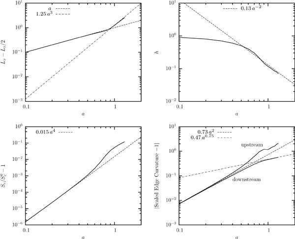
Scaling laws for a Skalak capsule with C = 1, αp = 0.05 and capillary number Ca = 0.1 in a square channel at steady state. (a) Capsule length Lx − Lz/2. (b) Minimum distance h between the capsule surface and the solid walls. (c) Capsule surface area Sc (scaled with the surface area undisturbed spherical shape). (d) Curvature at the downstream and upstream edges of the capsule (scaled with the curvature of the undisturbed spherical shape).
Figure 17 shows the power-law behavior of several physical properties of a capsule flowing in a square channel, including the capsule velocity Ux (with respect to the maximum or the average undisturbed velocity), the additional pressure drop ΔP+ and the maximum principal tension . It is of interest to note that the velocity difference is more appropriate for small capsules which flow with a velocity Ux smaller but close to the maximum undisturbed velocity . On the other hand, the velocity difference is more appropriate for moderate and large thick capsules a (i.e. for small gaps h), where the capsule flows with a velocity Ux greater but close to the average undisturbed velocity . Figure 17(c) shows that the additional pressure drop follows only one scaling law, i.e. ΔP+ ~ a5, for all capsule sizes studied.
FIG. 17.
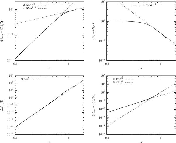
Scaling laws for a Skalak capsule with C = 1, αp = 0.05 and capillary number Ca = 0.1 in a square channel at steady state. (a) Capsule velocity . (b) Capsule velocity . (c) Additional pressure drop ΔP+. (d) Maximum principal tension among the spectral discretization points on the membrane.
We also found similar scaling laws (with identical power-law coefficients but different multiplication coefficients) for all geometric and physical properties of interest for capsule motion in cylindrical tubes. Figure 18 shows the power-laws for the capsule physical properties, i.e. capsule velocity, additional pressure drop and maximum principal tension. We emphasize that this figure shows clearly that for small and moderate sizes, the capsule velocity Ux and additional pressure drop ΔP+ are governed by exactly the same scaling laws as for high-viscosity droplets, i.e. the predictions of Hetsroni et al. [20] and Brenner [21] as we discuss in section 5.
FIG. 18.
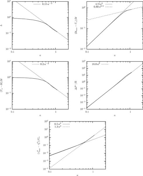
Scaling laws for a Skalak capsule with C = 1, αp = 0.05 and capillary number Ca = 0.1 in a cylindrical tube at steady state. (a) Minimum distance h between the capsule surface and the solid walls. (b) Capsule velocity . (c) Capsule velocity . (d) Additional pressure drop ΔP+. (e) Maximum principal tension among the spectral discretization points on the membrane.
References
- [1].Pozrikidis C, editor. Modeling and Simulation of Capsules and Biological Cells. Chapman and Hall; London: 2003. [Google Scholar]
- [2].Popel AS, Johnson PC. Microcirculation and Hemorheology. Annu. Rev. Fluid Mech. 2005;37:43–69. doi: 10.1146/annurev.fluid.37.042604.133933. [DOI] [PMC free article] [PubMed] [Google Scholar]
- [3].Abkarian M, Faivre M, Horton R, Smistrup K, Best-Popescu CA, Stone HA. Cellular-scale hydrodynamics. Biomed. Mater. 2008;3 doi: 10.1088/1748-6041/3/3/034011. 034011(1–13) [DOI] [PubMed] [Google Scholar]
- [4].Antia M, Herricks T, Rathod PK. Microfluidic modeling of cell-cell interactions in malaria pathogenesis. PLoS Pathog. 2007;3:0939–0948. doi: 10.1371/journal.ppat.0030099. [DOI] [PMC free article] [PubMed] [Google Scholar]
- [5].Chabert M, Viovy J-L. Microfluidic high-throughput encapsulation and hydrodynamic self-sorting of single cells. Proc. Natl. Acad. Sci. 2008;105:3191–3196. doi: 10.1073/pnas.0708321105. [DOI] [PMC free article] [PubMed] [Google Scholar]
- [6].Cranston HA, Boylan CW, Carroll GL, Sutera SP, Williamson JR, Gluzman IY, Krogstad DJ. Plasmodium falciparum maturation abolishes physiologic red cell deformability. Science. 1984;223:400–403. doi: 10.1126/science.6362007. [DOI] [PubMed] [Google Scholar]
- [7].Lensen D, Breukelen KV, Vriezema DM, Hest JCMV. Preparation of biodegradable liquid core PLLA microcapsules and hollow PLLA microcapsules using microfluidics. Macromol. Biosci. 2010;10:475–480. doi: 10.1002/mabi.200900404. [DOI] [PubMed] [Google Scholar]
- [8].Seiffert S, Thiele J, Abate AR, Weitz DA. Smart microgel capsules from macromolecular precursors. J. Am. Chem. Soc. 2010;132:6606–6609. doi: 10.1021/ja102156h. [DOI] [PubMed] [Google Scholar]
- [9].Lefebvre Y, Leclerc E, Barthès-Biesel D, Walter J, Edwards-Lévy F. Flow of artificial microcapsules in microfluidic channels: A method for determining the elastic properties of the membrane. Phys. Fluids. 2008;20:123102. [Google Scholar]
- [10].Prevot M, Cordeiro AL, Sukhorukov GB, Lvov Y, Besser RS, Möhwald H. Design of a microfluidic system to investigate the mechanical properties of layer-by-layer fabricated capsules. Macromol. Mater. Eng. 2003;288:915–919. [Google Scholar]
- [11].Teh S-Y, Lin R, Hung L-H, Lee AP. Droplet microfluidics. Lab Chip. 2008;8:198–220. doi: 10.1039/b715524g. [DOI] [PubMed] [Google Scholar]
- [12].Baroud CN, Gallaire F, Dangla R. Dynamics of microfluidic droplets. Lap Chip. 2010;10:2032–2045. doi: 10.1039/c001191f. [DOI] [PubMed] [Google Scholar]
- [13].Quéguiner C, Barthès-Biesel D. Axisymmetric motion of capsules through cylindrical channels. J. Fluid Mech. 1997;348:349–376. [Google Scholar]
- [14].Risso F, Collé-Pailot F, Zagzoule M. Experimental investigation of a bioartificial capsule flowing in a narrow tube. J. Fluid Mech. 2006;547:149–173. [Google Scholar]
- [15].Lefebvre Y, Barthès-Biesel D. Motion of a capsule in a cylindrical tube: effect of membrane pre-stress. J. Fluid Mech. 2007;589:157–181. [Google Scholar]
- [16].Skalak R, Tozeren A, Zarda RP, Chien S. Strain energy function of red blood cell membranes. Biophys. J. 1973;13:245–264. doi: 10.1016/S0006-3495(73)85983-1. [DOI] [PMC free article] [PubMed] [Google Scholar]
- [17].Doddi SK, Bagchi P. Lateral migration of a capsule in a plane Poiseuille flow in a channel. Int. J. Multiphase Flow. 2008;34:966–986. [Google Scholar]
- [18].Doddi SK, Bagchi P. Three-dimensional computational modeling of multiple deformable cells flowing in microvessels. Phys. Rev. E. 2009;79:046318. doi: 10.1103/PhysRevE.79.046318. [DOI] [PubMed] [Google Scholar]
- [19].Fiddes LK, Young EWK, Kumacheva E, Wheeler AR. Flow of microgel capsules through topographically patterned microchannels. Lab Chip. 2007;7:863–867. doi: 10.1039/b703297h. [DOI] [PubMed] [Google Scholar]
- [20].Hetsroni G, Haber S, Wacholder E. The flow in and around a droplet moving axially within a tube. J. Fluid Mech. 1970;41:699–705. [Google Scholar]
- [21].Brenner H. Pressure drop due to the motion of neutrally buoyant particles in duct flows. II. Spherical droplets and bubbles. Ind. Engng Chem. Fundam. 1971;10:537–543. [Google Scholar]
- [22].Lac E, Sherwood JD. Motion of a drop along the centreline of a capillary in a pressure-driven flow. J. Fluid Mech. 2009;10:27–54. [Google Scholar]
- [23].Yih C-S. Fluid Mechanics. West River Press; Ann Arbor: 1979. [Google Scholar]
- [24].Dimitrakopoulos P, Higdon JJL. On the displacement of three-dimensional fluid droplets from solid surfaces in low-Reynolds-number shear flows. J. Fluid Mech. 1998;377:189–222. [Google Scholar]
- [25].Dodson WR, III, Dimitrakopoulos P. Dynamics of strain-hardening and strain-softening capsules in strong planar extensional flows via an interfacial spectral boundary element algorithm for elastic membranes. J. Fluid Mech. 2009;641:263–296. [Google Scholar]
- [26].Lac E, Barthès-Biesel D, Pelekasis NA, Tsamopoulos J. Spherical capsules in three-dimensional unbounded Stokes flows: effect of the membrane constitutive law and onset of buckling. J. Fluid Mech. 2004;516:303–334. [Google Scholar]
- [27].Wang Y, Dimitrakopoulos P. Normal force exerted on vascular endothelial cells. Phys. Rev. Lett. 2006;96 doi: 10.1103/PhysRevLett.96.028106. 028106(1–4) [DOI] [PubMed] [Google Scholar]
- [28].Wang Y, Dimitrakopoulos P. Nature of the hemodynamic forces exerted on vascular endothelial cells or leukocytes adhering to the surface of blood vessels. Phys. Fluids. 2006;18 087107(1–14) [Google Scholar]
- [29].Wang Y, Dimitrakopoulos P. A three-dimensional spectral boundary element algorithm for interfacial dynamics in Stokes flow. Phys. Fluids. 2006;18 082106(1–16) [Google Scholar]
- [30].Dimitrakopoulos P. Interfacial dynamics in Stokes flow via a three-dimensional fully-implicit interfacial spectral boundary element algorithm. J. Comp. Phys. 2007;225:408–426. [Google Scholar]
- [31].Dodson WR, III, Dimitrakopoulos P. Spindles, cusps and bifurcation for capsules in Stokes flow. Phys. Rev. Lett. 2008;101:208102. doi: 10.1103/PhysRevLett.101.208102. [DOI] [PubMed] [Google Scholar]
- [32].Bretherton FP. The motion of long bubbles in tubes. J. Fluid Mech. 1961;10:166–188. [Google Scholar]
- [33].Hodges SR, Jensen OE, Rallison JM. The motion of a viscous drop through a cylindrical tube. J. Fluid Mech. 2004;501:279–30. [Google Scholar]
- [34].Stone HA. Interfaces: in fluid mechanics and across disciplines. J. Fluid Mech. 2010;645:1–25. [Google Scholar]
- [35].de Lózar A, Hazel AL, Juel A. Scaling properties of coating flows in rectangular channels. Phys. Rev. Lett. 2007;99:234501. doi: 10.1103/PhysRevLett.99.234501. [DOI] [PubMed] [Google Scholar]