Abstract
Polymer-based microneedles have drawn much attention in the transdermal drug delivery resulting from their flexibility and biocompatibility. Traditional fabrication approach deploys various kinds of molds to create sharp tips at the end of needles for the penetration purpose. This approach is usually time-consuming and expensive. In this study, we developed an innovative fabrication process to make biocompatible SU-8 microtubes integrated with biodissolvable maltose tips as novel microneedles for the transdermal drug delivery applications. These microneedles can easily penetrate the skin's outer barrier represented by the stratum corneum (SC) layer. The drug delivery device of mironeedles array with 1000 μm spacing between adjacent microneedles is proven to be able to penetrate porcine cadaver skins successfully. The maximum loading force on the individual microneedle can be as large as 7.36 ± 0.48N. After 9 min of the penetration, all the maltose tips are dissolved in the tissue. Drugs can be further delivered via these open biocompatible SU-8 microtubes in a continuous flow manner. The permeation patterns caused by the solution containing Rhodamine 110 at different depths from skin surface were characterized via a confocal microscope. It shows successful implementation of the microneedle function for fabricated devices.
INTRODUCTION
Generally speaking, drugs can be delivered into the human body through different means of administration. Among these means, injection and oral delivery are the most commonly used. However, the injection cannot be easily conducted by patients themselves because it requires trained personnel and may introduce pain during the injection step.1 The oral delivery sometimes is not effective as the pharmacological action of medicines could be affected by the internal digestion system, thus protein and DNA targeting drugs have a poor absorption rate.2 To overcome these drawbacks, transdermal drug delivery through microelectromechanical systems (MEMS) based microneedles has drawn much attention recently.3, 4, 5, 6, 7
In order to penetrate the skin's outmost layer (i.e., stratum corneum, SC) for effective application of drug delivery approaches, microneedles made by various materials, including silicon,8 stainless steel,9 titanium,10 tantalum,11 nickel,12 and ceramics,13 have been investigated. These materials are frequently used to offer the required mechanical strength for microneedles, which need to be inserted and to penetrate the skin in order to reach the desired tissues. Although microneedles can be fabricated into sharp shape for the easier penetration, such microneedles are prone to be damaged during the insertion process due to their frangibility.14 Moreover, most of them have unproven biocompatibility. As a result, polymer-based microneedles are receiving more and more attention. The SU-8 microneedles array, as a kind of biocompatible and inexpensive polymer-based device, is proposed as a suitable device in this study. In order to get ultra-sharp tips for the easy insertion, the fabrication of SU-8 vertical microneedles array usually requires a PDMS mold15, 16 or a stainless steel mold17 with excellent quality, but this approach makes the fabrication process time-consuming and expensive.
Meanwhile, dissolvable microneedles have been shown to encapsulate bioactive molecules and deliver their cargo into skin when microneedles are dissolved in body fluid.18, 19, 20, 21 In particular, dissolving microneedle patches for influenza vaccination using a simple patch-based system that enables delivery to skin's antigen-presenting cells has been investigated.22 Such results showed that dissolvable microneedles offer an attractive and effective mean to administer drugs while providing safety and immunogenicity. However, it is already reported that the drug releasing efficiency of these dissolvable microneedles, as well as coated microneedles, strongly depends on drugs' molecular size.23, 24 Delivery of large molecular drugs such as insulin has been already found to encounter an efficiency problem.25, 26 Combining dissolvable microneedles with microfluidic components is a promising way since this method can apply pressure on the drug solution to facilitate the large molecular drug diffusion process. Moreover, continuous delivery with the microfluidic component is expected to release large volumes. In this way, the device can support those vaccines requiring large dosage.27 However, so far, there are no published data reporting the dissolvable microneedles integrated with microfluidics. To ensure a high drug releasing efficiency and continuously provide a large volume of drugs via the temporary perforation of the skin by dissolvable microneedles systems, a novel dissolvable microneedles device comprising fluidic channels or microtubes which are connected with individual dissolvable tips would be highly desired.
In this study, we will demonstrate a new method to fabricate SU-8 microneedles. In order to overcome the barrier of SC layer, sharp dissolvable maltose tips are created on top of SU-8 vertical microtubes by the simple drawing lithography technology. After the maltose tips are dissolved by body fluid, SU-8 microtubes will efficiently flow a large volume of the desired drug. The experimental results indicate that this new device has promising potential in the transdermal drug delivery application.
DESIGN AND FABRICATION
Design considerations
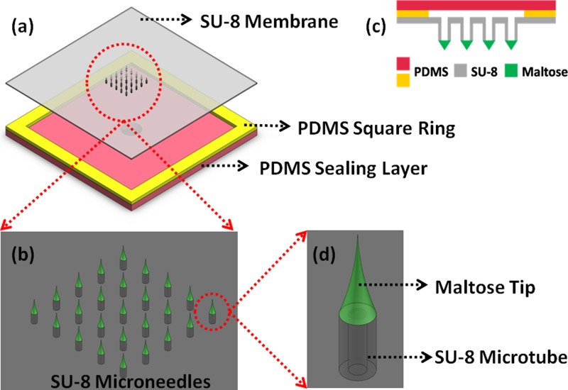
Conventionally, sharp microneedles are required to create microchannels in the SC layer for the further drug administration. Sharp microtips made of maltose have been reported as a method for forming holes in the SC layer, where drug solution could pass the perforated SC layer thereafter.28, 29, 30, 31 These reports show that maltose microtips have enough mechanical strength to be stably inserted into the SC layer. Fabrication of such sharp maltose microtips has been demonstrated by moldings and draw lithography based approaches.32 More importantly, maltose is a well-known dissolvable material in moisture environment, while Lee et al. reported that the maltose microtips are dissolvable in body fluid, i.e., biodissolvable materials.32 Therefore, we leverage the unique features of maltose based microtips, i.e., high mechanical strength and biodissolvability, and validate the feasibility of integration of sharp maltose tips on top of SU-8 microtubes in the present study (Fig. 1). After sharp maltose tips perforating the SC layer of the skin, maltose tips will be dissolved in the body fluid within a few minutes subsequently and drugs can be delivered through the SU-8 microtubes. Since the drugs are driven by pressure through microtubes in a continuous manner, the delivery volume is expected to be sufficient for some large dosage delivery purposes.
Figure 1.
Schematic illustration of the SU-8 microneedles. (a) Top view of the device structure. (b) A 5×5 SU-8 microneedles array. (c) Cross section of the device structure. (d) Single microneedle structure.
An array of 5 × 5 SU-8 microtubes is patterned on a 140 μm thick, 2.5 cm × 2.5 cm SU-8 membrane (Fig. 1a). Each SU-8 microtube is 350 μm high. The various spacing between two adjacent microtubes will be investigated and the fabrication results are discussed in Sec. 3 (Fig. 1b). The inner diameter of the SU-8 microtube is 150 μm, while the outer diameter is 300 μm (Fig. 1d). Maltose needles of around 1000 μm height are integrated on the SU-8 microtubes to ensure the ability of transdermal perforation. Two PDMS layers and the 2.5 cm × 2.5 cm SU-8 membrane are bonded together to form a sealed chamber for retaining drugs from the connection tube during delivery process. The 2.5 cm × 2.5 cm size of the device is designed on purpose in order to conceptualize a skin patch kind of drug delivery device. However, the critical area comprising the SU-8 microneedles at the center is only 6 mm × 6 mm. Large marginal space offers sufficient area to achieve good bonding between SU-8 layer and PDMS layer, i.e., tolerating higher pressure to drive drugs into tissues during the delivery process.
SU-8 microtubes fabrication
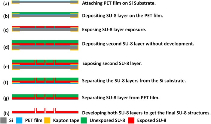
As shown in Fig. 2, SU-8 microtubes fabrication starts from a layer of Polyethylene Terephthalate (PET, 3 M USA) film pasted on the Si substrate by sticking the edge area with kapton tape (Fig. 2a). The PET film, a kind of transparent film not sticky at the both side, is used as a sacrificial template to dry release the final device from the Si substrate because of the poor adhesion between PET film and SU-8. Before the dry releasing process, all the following SU-8 processes will not make the device fall apart from the PET layer. Although in the work presented by Fernández et al.,33 only the kapton film is used for the release purpose, we found that when the SU-8 patterned area on the kapton film is large, tearing off the film from the kapton film without damaging the device requires extreme delicacy. This is because both the patterned SU-8 layer and Si substrate are rigid layers. However, in our process, the sticky kapton film just applied along the edges of samples to tightly fix with PET film can be easily removed after the device developed in SU-8 developer. The PET film with the SU-8 layer is separated from the Si substrate. Then SU-8 layer could be dry released from the PET film just by slightly bending the PET film.
Figure 2.
Fabrication process for SU-8 microtubes.
A 140 μm thick SU-8 layer is deposited on the fixed PET film (Fig. 2b). To ensure a smooth SU-8 surface, this deposition is conducted in two steps of coating with 70 μm layer each. In each step, SU-8 2050 is spun at 2000 rpm for 30 s, followed by prebaking steps at 65 °C for 10 min and 95 °C for 30 min. After the prebaking steps, this SU-8 layer is exposed under 450 mJ/cm2 ultraviolet (UV) energy to define the membrane structure on this layer (Fig. 2c). After exposure baking steps at 65 °C for 5 min and 95 °C for 15 min, another 350 μm SU-8 layer is directly deposited on this layer in two steps without development (Fig. 2d). If the first layer is developed to get patterns, the surface will not be smooth enough to achieve a uniform second SU-8 layer on it. With careful alignment, an exposure of 650 mJ/cm2 energy is performed on the second layer to get the pattern of SU-8 microtubes, which are precisely above the holes patterned on the first layer (Fig. 2e). After post exposure baking steps at 65 °C for 10 min and 95 °C for 30 min, then the SU-8 device with PET film is released from the silicon substrate by the same method described before (Figs. 2f, 2g). After soaking in an ultrasonic cleaner for 30 min, the SU-8 microtubes array on the membrane is developed (Fig. 2h).
PDMS bonding
To bond the PDMS layer with SU-8, PDMS with mixing ratio of prepolymer base and curing agent in 10:1 is prepared firstly. After degassing, PDMS is cured and cut into small pieces. Then the first PDMS layer with square ring structure is treated with N2 plasma to introduce amino groups on one side. When this PDMS surface is contacted with the bottom side of SU-8 surface having epoxy groups on surface, interfacial amine-epoxide chemical reaction takes place at an elevated temperature. Therefore, after cured at 120 °C for 15 min, PDMS is permanently bonded with SU-8 layer.
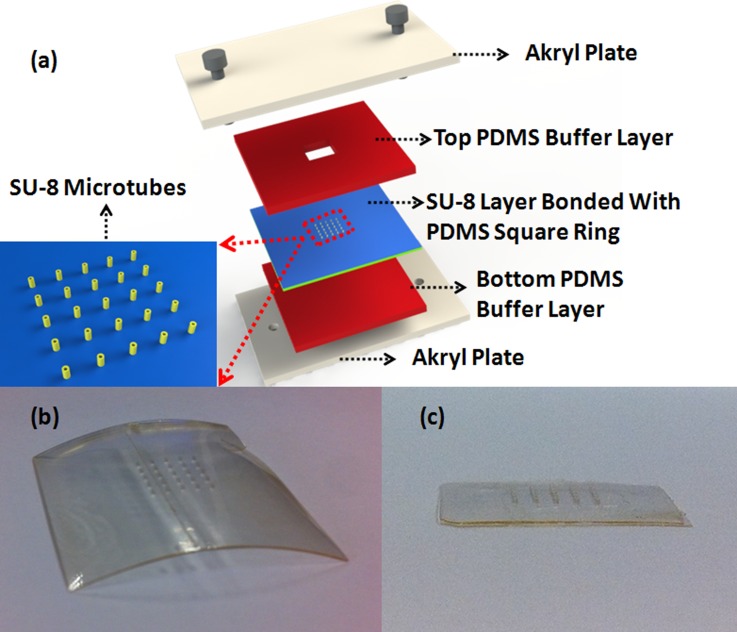
After the SU-8 membrane is released from the PET film, it bends during the developing process (Fig. 3b), due to residue stress gradients in SU-8 membrane.34 Here, a homemade stage is used to reduce this effect. As shown in Fig. 3a, two akryl plates are applied to clamp SU-8 membrane bonded with PDMS layer. Other two PDMS layers are used as soft buffer layers to protect the device. This stage offers a flat surface and uniform pressure on the SU-8 membrane. When put into the 120 °C oven, the SU-8 membrane will slightly deform because the bonded PDMS layer has a thermal expansion at this high temperature. Such effect relieves the previous bended layers and leads to a more flat surface (Fig. 3c). This flat surface is critical for the following maltose tips drawing process. Then O2 plasma is performed on the opposite side of the first PDMS layer and one side of the second PDMS layer. After attaching these two surfaces together, two PDMS layers are bonded firmly together to form a fluidic chamber for the drug to flow into microtubes.
Figure 3.
(a) Schematic illustration of the homemade stage to ensure flat SU-8 membrane surface. (b) SU-8 membrane bends after development. (c) After bonded with PDMS and clamped in the stage, the membrane becomes flat.
Drawing process of maltose tips
Maltose needles are integrated on the SU-8 microtubes by the drawing lithography technology. Lee et al. encapsulated the drugs in maltose and patterned the maltose tips by drawing lithography.32 Since the temperature in this method must be higher than 100 °C, a large group of drugs cannot stand at this temperature and will be degenerated. In our device, drugs will be delivered through SU-8 microtubes and the maltose is just used as sharp tips for skin penetration. Without facing the high temperature effect, our device is a generic platform to administer various kinds of drugs.
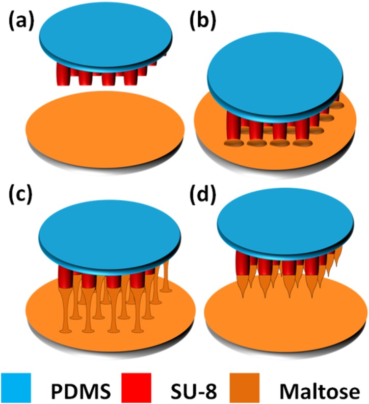
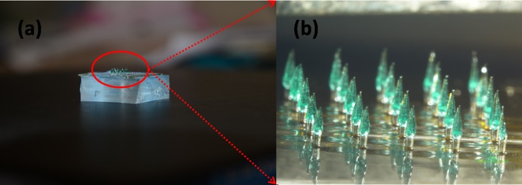
As shown in Fig. 4, fabrication of maltose tips on top of SU-8 microtubes is divided into four steps. Firstly, concentrated maltose solution containing methylene blue, which is used for a better inspection during penetration process, is dripped on a glass slide. The slide is kept at 140 °C on the hotplate until the water inside maltose solution completely vaporizes and maltose becomes liquid state (Fig. 4a). Secondly, device of SU-8 microtubes is fixed on a precision stage which can control the position of SU-8 microtubes in three-dimension. Then, we immerse the SU-8 microtubes into the liquid maltose at 140 °C and maltose liquid coat on the SU-8 microtubes' surface (Fig. 4b). Thirdly, we gradually increase the temperature of liquid maltose and start drawing SU-8 microtubes away from interface of the liquid maltose and air (Fig. 4c). Finally, when the temperature rises up to 160 °C, drawing speed is increased. Since the maltose liquid is less viscous at higher temperature, the connection between the SU-8 microtubes and surface of the liquid maltose becomes individual maltose bridge and shrinks gradually, and then breaks. The end of shrunk maltose bridge forms a sharp tip on top of each SU-8 microtube when the connection is collapsed (Fig. 4d). Fig. 5 shows the final drug delivery device containing SU-8 microtubes integrated with maltose tips and microfluidics, e.g., channels and the chamber formed by PDMS.
Figure 4.
Fabrication process for maltose tips. (a) Expelling water at 140 °C. (b) Immersing microtubes into the maltose at 140 °C. (c) Drawing the tips at end of the microtubes when the temperature increases up to 160 °C. (d) Increasing drawing speed to form sharp tips.
Figure 5.
(a) Optical image for the finished SU-8 microneedles. (b) Detailed illustration image for the microneedles array.
RESULTS AND DISCUSSION
Optimization of spacing between maltose tips
The detailed mathematic model for drawing lithography has been reported and discussed by Lee.35 To ensure the stronger and shorter maltose tips of a mircroneedle array for an easier skin penetration, experiments are conducted to optimize parameters in the drawing process. Temperature of melted maltose during drawing step and drawing speed are identified as the key parameters to get up to 1000 μm tall maltose sharp tips on the SU-8 microtubes. Although the maltose tip can be easily and routinely formed on top of SU-8 microtubes at 140 °C and optimized drawing speed, the formation of uniform maltose tips array also depends on the spacing between two adjacent SU-8 microtubes.
When the maltose melted at 140 °C, the planar extensional viscosity in maltose easily leads adjacent maltose tips to clusters. We have investigated various spacing between two adjacent maltose tips to get the minimum spacing. The height of microtubes changes from 150 μm to 350 μm with the interval of 100 μm, while the spacing changes from 300 μm to 1200 μm with the interval of 300 μm. There are in total 12 different dimensions. Four chips are tested for each dimension as a group and the total trails are 48. Since there are 25 microneedles on each chip, there are in total 100 microneedles on 4 chips in each group. After the drawing process, the results for each group, 100 microneedles on 4 chips, are counted and converted as the ratio on a single 5×5 array for an average. Table TABLE I. shows the observed data about the ratio of formed individual maltose tips over the formed clustered tips in these 48 samples. We concluded that individual maltose tips are successfully derived from samples of microtubes with the height beyond 350 μm and the spacing larger than 900 μm. As a result, we prepared many samples of SU-8 microtubes of 350 μm height and 1000 μm spacing for further maltose integration experiment in our study.
TABLE I.
Ratio of individual maltose tips to clustered maltose tips among a 5 × 5 microneedles array.
| Spacing between two SU-8 microtubes | |||||
|---|---|---|---|---|---|
| 300 μm | 600 μm | 900 μm | 1200 μm | ||
| Height of microtube | 150 μm | 0/25 | 5/20 | 15/10 | 25/0 |
| 250 μm | 0/25 | 13/12 | 21/4 | 25/0 | |
| 350 μm | 0/25 | 17/8 | 25/0 | 25/0 | |
Mechanical strength of the microneedles
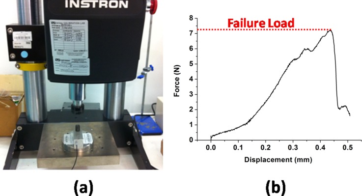
To ensure both the adequate adhesion property between the maltose tip and SU-8 microtubes, and the sufficient stiffness of the SU-8 microtubes for successful penetration, the mechanical strength of microneedles is studied with a similar method reported by Mansoor et al.36 As shown in Fig. 6a, Instron Microtester 5848 (Instron, USA) is used for the stiffness testing. A typical result is shown in Fig. 6b. During the testing, the breakage of microneedles only occurs at the interface between SU-8 microtubes and maltose tips when the exerting load is larger than the threshold value. However, the SU-8 microtubes are strong enough to stand the pressure. After characterization of 20 samples, the average threshold value is 7.36 ± 0.48 N for the microneedles (300 μm at microneedle base and 1000 μm high). Since the minimal force required for a successful penetration is reported to be less than 1 N with the similar microneedle dimension,37 the device is reliable during the penetration process.
Figure 6.
(a) Testing setup for the microneedle mechanical testing. (b) A typical microneedle stiffness testing result.
Characterization of penetration
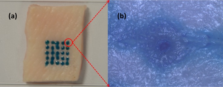
Fig. 7a shows the insertion result of a 5 × 5 microneedles array into a porcine cadaver skin. After the insertion, maltose tips are rapidly dissolved once inserted in the tissue. Methylene blue is added into the maltose for inspection purpose. Ten minutes after insertion, 25 blue traces are easily found, which matched the pattern of the microneedle array. The optical microscope image in Fig. 7b shows a hole perforated in the skin after we cleaned the dissolved maltose mixed with methylene blue from the skin surface. During the insertion experiment, we have to avoid the shear force influence caused by deformed skin surface on the individual maltose tip in order to get successful microneedle penetration for the whole array. We used precision stages to hold the microneedle device substrate and control the relative position of device substrate and skin sample.
Figure 7.
Penetration testing results on the porcine cadaver skin.
Dissolving of maltose tips and demonstration of injection via SU-8 microtubes
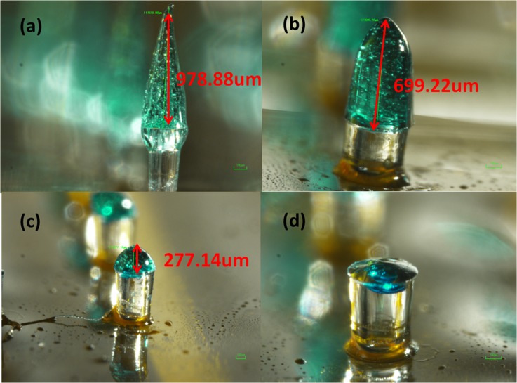
In order to check whether the maltose tips could be dissolved once inserted in the tissue, four chips with the same maltose tips height are inserted into the skin and taken out one by one with 3 min interval. Maltose tips are gradually dissolved versus increased time as shown in Fig. 8. After 9 min, the maltose tips are totally dissolved and the lumens of SU-8 microtubes are observed from the top view. Different from the traditional dissolvable needles which encapsulates drugs into the needles, this microneedle array is expect to allow large volume of drugs to pass through via the remaining SU-8 microtubes inside the skin.
Figure 8.
Maltose tips dissolving process. (a) The original sharp maltose tip. (b) Maltose tip after inserted into skin for 3 min. (c) Maltose tip after inserted into skin for 6 min. (d) Maltose tip after inserted into skin for 9 min.
Injection fluorescent solution into skin sample
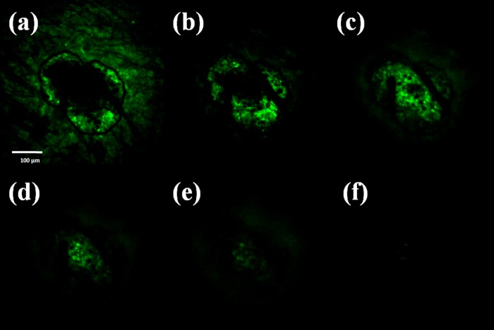
To verify that the drug solution can be delivered into tissue, a physiological saline solution containing Rhodamine 110 (Sigma-Aldrich, Singapore) is delivered through the SU-8 microtubes after the pure maltose tips are dissolved. The representative results are then investigated via a confocal microscope (Fig. 9). The permeation pattern of the solution along the microchannel confirms the solution delivery results. The black area serves as a control area without any diffused solution. In contrast, the illuminated tissues in Fig. 9 indicate the area where the solution has diffused to. The images are taken from the depth of 30 μm to 180 μm below the skin surface. Since the microchannel is created by the conical maltose tips, the diameter of the microchannel decreases as the focus depth increases. The following diffusion area is dependent on the microchannel dimension and also decreases accordingly.
Figure 9.
Images of confocal microscopy of the site where one microneedle inserted shows that the fluorescent solution is delivered into the tissue underneath the skin surface. Optical section depths are (a) 30 μm, (b) 60 μm, (c) 90 μm, (d) 120 μm, (e) 150 μm, and (f) 180 μm below the skin surface.
CONCLUSION
Vertical SU-8 microneedles integrated with maltose tips are fabricated by an innovative process in this study. It is a firstly reported microfluidic device for drug delivery application using biocompatible SU-8 microtubes and biodissolvable maltose tips. By using UV lithography, 350 μm high vertical hollow microtubes array can be patterned. Sharp maltose tips are integrated on the top of SU-8 microtubes by drawing lithography technology. To get repeatable fabrication results of sharp maltose tips on SU-8 microtubes, design parameters such as temperature of melted maltose during drawing step, drawing speed, height of SU-8 microtubes, and spacing between two individual SU-8 microtubes are optimized. The fabricated microneedles can penetrate into the skin easily and deliver drugs to tissues under it. PDMS layers are bonded with SU-8 film to form microfluidics in order to distribute solution and vaccine in this device and support the administration of drug. By using biocompatible SU-8 microtubes and biodissolvable maltose tips, this new microfluidic device provides possible and inexpensive means for self-administration of drugs at home.
ACKNOWLEDGMENTS
This work was supported in part by the Academic Research Committee Fund MOE2009-T2-2-011 (Nanoneedle devices for transdermal vaccine delivery) at the National University of Singapore under Grants No. R-263000598112 and R-398000068112.
References
- Nir Y., Paz A., Sabo E., and Potasman I., Am. J. Trop. Med. Hyg. 68, 341 (2003). [PubMed] [Google Scholar]
- Singh R., Singh S., and Lillard J. W., J. Pharm. Sci. 97, 2497 (2008). 10.1002/jps.21183 [DOI] [PMC free article] [PubMed] [Google Scholar]
- Bariya S. H., Gohel M. C., A. Mehta T., and Sharma O. P., J. Pharm. Pharmacol. 64, 11 (2012). 10.1111/j.2042-7158.2011.01369.x [DOI] [PubMed] [Google Scholar]
- Singh T. R. R., Dunne N. J., Cunningham E., and Donnelly R. F., Recent. Pat. Drug. Deliv. Formul. 5, 11 (2011). 10.2174/187221111794109484 [DOI] [PubMed] [Google Scholar]
- Ryan A. D. W., Donnelly F., and Raj Singh T. R., Drug Deliv. 17, 187 (2010). 10.3109/10717541003667798 [DOI] [PMC free article] [PubMed] [Google Scholar]
- Banga A. K., Expet. Opin. Drug. Deliv. 6, 343 (2009). 10.1517/17425240902841935 [DOI] [PubMed] [Google Scholar]
- Arora A., Prausnitz M. R., and Mitragotri S., Int. J. Pharm. 364, 227 (2008). 10.1016/j.ijpharm.2008.08.032 [DOI] [PMC free article] [PubMed] [Google Scholar]
- Wilke N., Mulcahy A., Ye S.-R., and Morrissey A., Microelectron. J. 36, 650–656 (2005). 10.1016/j.mejo.2005.04.044 [DOI] [Google Scholar]
- Alarcon J. B., Hartley A. W., Harvey N. G., and Mikszta H. A., Clin. Vaccine Immunol. 14, 375 (2004). 10.1128/CVI.00387-06 [DOI] [PMC free article] [PubMed] [Google Scholar]
- Matriano J., Cormier M., Johnson J., Young W., Buttery M., Nyam K., and Daddona P., Pharm. Res. 19, 63 (2002). 10.1023/A:1013607400040 [DOI] [PubMed] [Google Scholar]
- Omatsu T., Chujo K., Miyamoto K., Okida M., Nakamura K., Aoki N., and Morita R., Opt. Express. 18, 17969 (2010). 10.1364/OE.18.017967 [DOI] [PubMed] [Google Scholar]
- Jung P., Lee T. W., Oh D. J., Hwang S. J., Jung I., Lee S., and Ko J., Sens. Mater. 20, 45 (2008). [Google Scholar]
- Bystrova S. and Luttge R., Microelectron. Eng. 88, 1681 (2011). 10.1016/j.mee.2010.12.067 [DOI] [Google Scholar]
- Yang M. and Zahn J. D., Biomed. Microdevices 6, 177 (2004). 10.1023/B:BMMD.0000042046.07678.2e [DOI] [PubMed] [Google Scholar]
- Wang P. C., Paik S. J., Kim J., Kim S. H., and Allen M. G., in Proceedings of the IEEE MEMS (Cancun, Mexico, 2011), p. 1039.
- Wang P. C., Wester B. A., Rajaraman S., Paik S., Kim S., and Allen M. G., in Proceedings of the IEEE EMBC (Minneapolis, MN, 2009), p. 7029.
- Yung K. L., Xu Y., Kang C., Liu H., Tam K. F., Ko S. M., Kwan F. Y., and Lee T. M. H., J. Micromech. Microeng. 22, 015016 (2012). 10.1088/0960-1317/22/1/015016 [DOI] [Google Scholar]
- Miyano T., Tobinaga Y., Kanno T., Matsuzaki Y., Takeda H., Eakui M., and Hanada K., Biomed. Microdevices 7, 185 (2005). 10.1007/s10544-005-3024-7 [DOI] [PubMed] [Google Scholar]
- Ito Y., Yoshimitsu J., Shiroyama K., Sugioka N., and Takada K., J. Drug Target 14, 255 (2006). 10.1080/10611860600785080 [DOI] [PubMed] [Google Scholar]
- Kommareddy S., Baudner B. C., Oh S., Kwon S. Y., Singh M., and Ohagan D. T., J. Pharm. Sci. 101, 1021 (2012). 10.1002/jps.23019 [DOI] [PubMed] [Google Scholar]
- Kim C. S., Ahn Y. C., Petra W. S., Oh S., Chen Z. O., and Kwon Y. J., Biomed. Opt. Express 1, 106 (2010). 10.1364/BOE.1.000106 [DOI] [PMC free article] [PubMed] [Google Scholar]
- Sullivan S. P., Koutonanos D. G., Martin M. P., Lee J. W., Zarnitsyn V., Choi S. O., Murthy N., Compans R. W., Skountzou I., and Prausnitz M. R., Nat. Med. 16, 915 (2010). 10.1038/nm.2182 [DOI] [PMC free article] [PubMed] [Google Scholar]
- Park J. H., Allen M. G., and Prausnitz M. R., Pharm. Res. 23, 1008 (2006). 10.1007/s11095-006-0028-9 [DOI] [PubMed] [Google Scholar]
- Park J. H., Choi S. O., Seo S., Choy Y. B., and Prausnitz M. R., Eur. J. Pharm. Biopharm. 76, 282 (2010). 10.1016/j.ejpb.2010.07.001 [DOI] [PubMed] [Google Scholar]
- Qin G., Gao Y., Wu Y., Zhang S., Qiu Y., Li F., and Xu B., Nanomed. Nanotechnol. 8, 221 (2012). 10.1016/j.nano.2011.05.017 [DOI] [PubMed] [Google Scholar]
- Ozsoy Y., Gungor S., and Cevher E., Molecules 14, 3754 (2009). 10.3390/molecules14093754 [DOI] [PMC free article] [PubMed] [Google Scholar]
- heath D., Robinson C., Shakes T., Huang Y., Gulnur T., Shi B., Zhang Z., Anderson G. A., and Lightowlers M. W., Vaccine 30, 3076 (2012). 10.1016/j.vaccine.2012.02.073 [DOI] [PubMed] [Google Scholar]
- Li G., Badkar A., Nema S., Kolli C. S., and Banga A. K., Int. J. Pharm. 368, 109 (2009). 10.1016/j.ijpharm.2008.10.008 [DOI] [PubMed] [Google Scholar]
- Li G., Badkar A., Kalluri H., and Banga A. K., J. Pharm. Sci. 99, 1931 (2010). 10.1002/jps.22159 [DOI] [PubMed] [Google Scholar]
- Kalluri H. and Banga A. K., Pharm. Res. 28, 82 (2011). 10.1007/s11095-010-0122-x [DOI] [PubMed] [Google Scholar]
- Kolli C. S. and Banga A. K., Pharm. Res. 25, 104 (2008). 10.1007/s11095-007-9350-0 [DOI] [PubMed] [Google Scholar]
- Lee K., Lee C., and Jung H., Biomaterials 32, 3134 (2011). 10.1016/j.biomaterials.2011.01.014 [DOI] [PubMed] [Google Scholar]
- Fernández L. J., Altuna A., Tijero M., Gabriel G., Villa R., Rodríguez M. J., Batlle M., Vilares R., Berganzo J., and Blanco F. J., J. Micromech. Microeng. 19, 025007 (2009). 10.1088/0960-1317/19/2/025007 [DOI] [Google Scholar]
- Keller S., Haefliger D., and Boisen A., J. Micromech. Microeng. 20, 45024 (2010). 10.1088/0960-1317/20/4/045024 [DOI] [Google Scholar]
- Lee K. and Jung H., Biomaterials 33, 7309 (2012). 10.1016/j.biomaterials.2012.06.065 [DOI] [PubMed] [Google Scholar]
- Mansoor I., Häfeli U. O., and Stoeber B., J. Microelectromech. Syst. 21, 44 (2012). 10.1109/JMEMS.2011.2174429 [DOI] [Google Scholar]
- Olatunji O., Das D. B., Garland M. J., Belaid L. U. C., and Donnelly R. F., J. Pharm. Sci. 102, 1209 (2013). 10.1002/jps.23439 [DOI] [PubMed] [Google Scholar]


