

Abstract
Coupling of the localized surface plasmons between two closely apposed gold nanoparticles (nanoantenna) can cause strong enhancements of fluorescence or Raman signal intensity from molecules in the plasmonic “hot-spot”. Harnessing these properties for practical applications is challenging due to the need to fabricate gold particle arrays with well-defined nanometer spacing and a means of delivering functional molecules to the hot-spot. We report fabrication of billions of plasmon-coupled nanostructures on a single substrate by a combination of colloid lithography and plasma processing. Controlled spacing of the nanoantenna gaps is achieved by taking advantage of the fact that polystyrene particles melt together at their contact point during plasma processing. The resulting polymer thread shadows a gap of well-defined spacing between each pair of gold triangles in the final array. Confocal surface-enhanced Raman spectroscopy imaging confirms the array is functionally uniform. Furthermore, a fully intact supported membrane can be formed on the intervening substrate by vesicle fusion. Trajectories of freely diffusing individual proteins are traced as they sequentially pass through, and are enhanced by, multiple gaps. The nanoantenna array thus enables enhanced observation of a fluid membrane system without static entrapment of the molecules.
Keywords: Lipid membranes, nanoantennas, fluorescence enhancement, Raman spectroscopy
Resonant optical nanoantennas are capable of confining far field propagating light to the optical near-field, which offers intriguing possibilities for imaging and spectroscopy.1,2 Low quantum efficiency dyes in particular can experience thousand-fold enhancements of fluorescence emission.3 Such strong signal intensities from weak quantum emitters could greatly expand the number of fluorophores suitable for single molecule studies.4 Furthermore, label-free imaging and chemical analysis is possible by utilizing the plasmonic properties of optical nanoantennas for surface-enhanced Raman spectroscopy (SERS) and imaging.5,6 It is mandatory, however, that the molecules of interest are precisely positioned within nanoantenna to achieve such signal enhancements.7 This generally requires direct adsorption onto the nanoantenna, which imposes serious restrictions on utility. Molecules in living systems, for example, are generally in perpetual states of motion. Indeed it is often the movement and interactions among molecules, more so than their static positions, that captures the functional essence of a biological system. Any nanoantenna-based strategy that involves direct adsorption of the molecule of interest onto the nanoantenna intrinsically removes that molecule from the functioning ensemble and thus cannot report its natural behavior.
One experimental platform that has successfully integrated nanometer-scale metallic structures into fluid lipid membranes and living cells without interfering with biological function is the patterned supported membrane.8−12 Phospholipid vesicles can adsorb and fuse with a silica surface to form a single, continuous bilayer membrane by a self-assembly process.13 The resulting supported lipid bilayer is separated from the underlying substrate by a thin water layer and lipid molecules or lipid anchored proteins exhibit lateral mobility comparable to free membranes.14 Furthermore, supported membranes can be readily interleaved among metallic nanostructures on the same substrate.15−19 Boundary defects can be minimal in these systems and, importantly, essentially all molecules in the supported membrane are fluid up to very close proximity to the metal structures. This characteristic has proven critically important for some of the live cell experiments, which relied on substrate structures to control the movement of molecules in living cells with nanometer precision.10,12 These successful applications of nanopatterned supported membranes in studies of living cells inspired the following investigation into the incorporation of resonant nanoantennas into such systems.
The integration of optical nanoantennas within supported membranes requires highly reproducible fabrication technology to provide large arrays of metallic nanoparticles with controlled size and geometry. Fabrication of plasmon-coupled nanostructures often relies on top-down methods, such as electron beam lithography,3,20 which are limited by low sample throughput and cost. Colloidal lithography is an alternative strategy in which a self-assembling hexagonal monolayer of polymer spheres is used to shadow mask the substrate for subsequent metal deposition followed by removal of the colloidal mask.21 This has been successfully used to produce large arrays of gold nanoparticles and trianges.21,22 For the strongest plasmonic coupling, it is necessary to control the distance between nanotriangles to only a few nanometers.7 The general applicability of nanotriangle arrays for plasmonic sensing and Raman spectroscopy has been demonstrated in principle,23 but practical control of the gap spacing has been problematic. Approaches, such as angle deposition24 and plasma treatment25 of the colloid mask, have been pursued with the aim of reducing the particle spacing. However, to our knowledge all approaches reported to date have in common that the gap sizes are dependent on the diameter of the colloidal spheres. In other words, it has not been possible to decouple the size of the gold nanotriangles (which determines their surface plasmon resonance frequency) from the tip-to-tip distance between the individual nanoparticle features (which is responsible for the field enhancement).
Here we describe a protocol to control the tip-to-tip distance between neighboring gold nanotriangles in the 5–100 nm range using a refined combination of colloid lithography and subsequent plasma processing (Figure 1A–C). This is achieved by taking advantage of the fact that polystyrene particles melt together at their contact point during plasma processing.26 The resulting polymer thread (Figure 1C) shadows a gap of well-defined spacing between each pair of triangles in the final array (Figure 1D–G).
Figure 1.
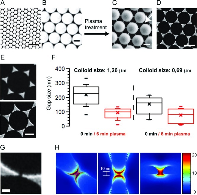
Bow-tie nanoantenna fabrication. (A,B) Polystyrene spheres form a hexagonal monolayer by self-assembly on top of a solid substrate (scale bar A, 5 μm; scale bar B, 1 μm). (C) Air plasma treatment leads to formation of connection between individual particles (scale bar: 1 μm). (D) The polymer thread serves as a shadow mask for gold evaporation. After particle lift-off, an array of separated gold nanotriangles remains on the substrate (scale bar: 1 μm). (E) The gap size between the gold nanotriangles is effectively reduced by the plasma treatment (scale bar: 1 μm). (F) After 6 min plasma etching, the mean gap size for 1.26 μm polystyrene particles was 93 nm with the smallest gaps being 10 nm. For a particle mask with 0.69 μm particles the mean gap size was found to be 75 nm with over 30% of all gaps being smaller than 50 nm and over 15% being smaller than 20 nm. (G) SEM micrograph of a 10 nm gap (scale bar: 100 nm). (H) FEA of the E-field enhancement E/E0 for a 10 nm gap. Strongest enhancement is observed at the nanoantenna edges but the plasmonic mode of the enhanced E-field extends further into the nanogap.
A large crystalline monolayer of colloidal spheres (1.26 or 0.69 μm in diameter are used here) is prepared on the surface on an activated glass slide by self-assembly of the colloidal particles. The polymer spheres are then dry-etched using isotropic air plasma. The plasma treatment has two effects on the colloid monolayer: (i) particles are uniformly etched from all sides, so that the overall particle size is reduced while each particle keeps its original position; and (ii) connecting threads are formed at the points where two neighboring spheres were touching (Figure 1C). When used as a shadow mask for thermal deposition of a thin gold film (15 nm), shadows from these nanothreads defined the final tip-to-tip distances between individual triangles, which are now much smaller than that from a pure monolayer alone (Figure 1D,E). For comparison, the mean gap size on a control substrate without plasma processing for a 1.26 μm particle layer was found to be around 218 nm. By contrast, after 6 min plasma etching the mean gap size was 93 nm with over 10% of all gaps being smaller than 50 nm (Figure 1F). The distribution of gap sizes is largely a consequence of the plasma machinery and the metal evaporation processes. With increasing plasma processing time, the connecting thread thins and eventually gets etched away, ultimately resulting in a large array of isolated corrals surrounded by a continuous gold boundary.
Finite element analysis (FEA) was used to model the field enhancement (expressed as E/E0) of a three-dimensional (3D) model of an actual 10 nm nanogap, as measured by scanning electron microscopy (SEM). Although the highest field enhancement is at the edges of the triangular tips, substantial enhancement exists over the whole gap (Figure 1G,H). All molecules diffusing within an interleaving supported membrane will periodically pass through gaps and experience repeated fluorescence or Raman signal enhancements.
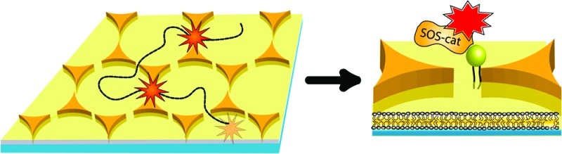
We use the nanoantenna array to examine the movement of individual SOS (Son of Sevenless) molecules interacting with their natural membrane-linked Ras ligands (Figure 2A).27 SOS is a guanine nucleotide exchange factor (GEF) enzyme that activates Ras by catalyzing the exchange of Ras-bound GDP for GTP, which results in subsequent downstream signaling in the MAP Kinase cascade. SOS-catalyzed nucleotide exchange in Ras is critically important in many aspects of health and disease and the supported membrane platform is emerging as a powerful strategy for quantitative studies of these enzymatic processes.28 The supported membrane was formed from maleimide-functionalized small unilamellar vesicles (SUVs) prepared from DOPC (83 mol %), DOPS (10 mol %) and MCC-PE (7 mol %). SUVs fuse with and ultimately fully coat the bare glass substrate, surrounding the gold triangles with a continuous supported membrane.29 For these experiments, the nanoantenna arrays were fabricated from a 0.69 μm particle layer after 6 min plasma treatment resulting in a mean tip-to-tip distance of 75 nm (determined by SEM) with over 15% of the gaps between 5 and 20 nm wide (Figure 1F). Ras-GTP-Atto488 (here referred to as Ras) was bound to the surface via Michael addition of a unique engineered c-terminal cysteine on H-Ras(1–181) to the maleimide phospholipid headgroup (MCC-PE). The resulting covalent carbon–sulfur bond stably associates Ras with the membrane near the position of its natural membrane anchorage. Fluorescence recovery after photobleaching (FRAP) experiments were performed on the supported membrane to monitor fluidity throughout the nanogap array and to ensure that the Ras proteins were diffusing through the gaps (Supporting Information). SOScat (C838A, C635A, C980S, E716C) was expressed as previously described28 and was labeled site-specifically at a unique engineered cysteine (E716C) with Atto647N-maleimide and does not bind membranes on its own. When SOScat is added to Ras-functionalized supported membranes, it binds to the membrane-linked Ras and diffuses on the supported bilayer. Single-molecule tracking and fluorescence intensity measurements were performed by total internal reflection fluorescence (TIRF) microscopy.
Figure 2.

Single molecule fluorescence enhancement. (A) A large array of plasmonic gold-bowtie antennas is surrounded by a fluid supported lipid bilayer. Fluorescently labeled SOScat-Atto647N is bound to Ras via protein–protein interactions. Ras is anchored in the upper leaflet of the supported lipid bilayer via a lipid anchor. Fluorophores tethered to the supported membrane can diffuse in the plane and thereby pass through the nanogaps (red dotted line). Single molecules are detected as bright spots. When a fluorophore is outside the gaps it fluoresces with lower baseline intensity than when passing through a bowtie gap, where the strongly coupled electric field causes enhancement of photon emission. Because the surface is a contiguous 2D fluid, each fluorophore can sample many gaps or sample the same gap repeatedly. (B) Fluorescence intensity of one molecule gets enhanced between 2.5 and 3.2 times while diffusing through different gaps at different time-spots. (C,D) Fluorescence intensity of three different molecules gets enhanced between 2.5 and 6.8 times as they diffuse through the same gap at different time-points. The white arrow in the RICM image indicates the position of the nanogap (scale bar 1 μm). The single-step photobleaching at the end of each fluorescence track is indicative of single molecule observations.
Individual SOScat proteins were observed diffusing on the bilayer membrane and passing through multiple nanogaps before photobleaching. Outside the gaps, the molecules emit fluorescence at low baseline intensity. When passing through a nanoantenna gap, the emission rate of the fluorescent molecule is enhanced. The moving molecules thus exhibit a position-dependent intensity profile, effectively flashing brightly as they pass through the gaps (Figure 2B–D). The one-step photobleaching at the end of each fluorescence track is a direct indication that a single fluorophore was being imaged. Fluorescence enhancements from 2.5–6.8 fold were measured from individual nanoantenna gaps.
The most distinctive feature of this system is that individual molecules can traverse multiple nanoantenna gaps without any evident interference of the gap on their mobility or the functional interaction between SOS and Ras. Similarly, multiple molecules can traverse the same nanogap at different times (Figure 2C). These properties allow for cumulative observation of every molecule in the sample, rather than just a select few that happen to be well positioned, without altering their functional movement or interactions.
Raman spectroscopy is generally advantageous over fluorescence when it comes to detecting and identifying chemical compounds because Raman signals arise from distinct vibrational energy levels of the molecule. Each spectrum therefore contains detailed chemical information without requiring an additional fluorescent tag. Confocal surface-enhanced Raman spectroscopy (SERS) imaging was performed on nanoantenna substrates similar to those that were used for fluorescence enhancement experiments. Before imaging, a substrate was immersed in a 0.02 mg/mL solution of malachite green isothiocyanate (MGITC) in IPA. After 12 h incubation time, the samples were rinsed several times with IPA and blow-dried with nitrogen. Raman imaging was performed in air using a confocal Raman microscope with optical fiber coupling at a laser wavelength of 532 nm. To unequivocally demonstrate the enhancement of the Raman signal by the nanoantenna array, we imaged an area on the substrate near an unpatterned gold patch that originated from a defect in the colloid monolayer (Figure 3A,B). The chemical image of this area for the 1528–1662 cm–1 Raman bands is shown in Figure 3C.
Figure 3.
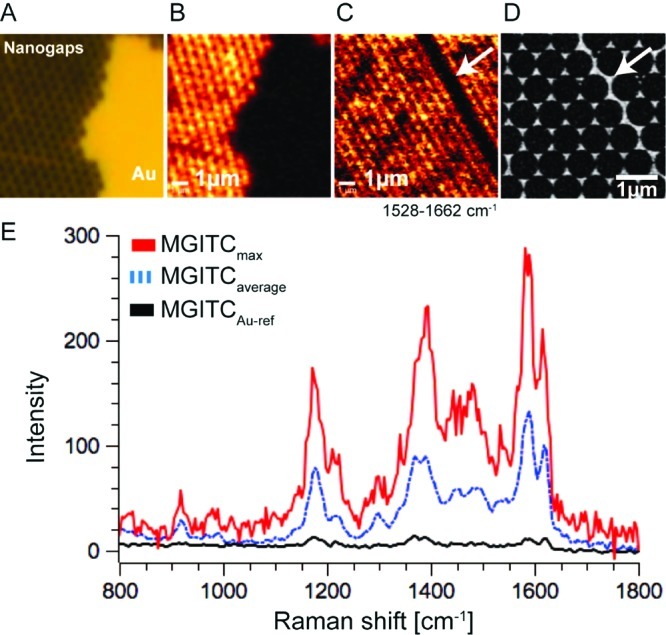
Confocal Raman imaging spectroscopy of MGITC on the nanogap array. (A) Bright-field image of the nanogap area and a gold patch that resulted from a defect in the colloid mask. Raman imaging spectroscopy was performed right over the edge of the nanogap array and the gold thin film. (B,C) Chemical Raman images for wavenumbers between 1528 and 1662 cm–1. A higher Raman intensity is measured on the nanogap array. (D) SEM micrograph of an area comparable to C. The dark stripe in C is caused by a grain boundary of the crystalline colloid particle mask. After metal evaporation, the nanogap mesh is disrupted along the grain boundary. (E) Raman spectra of MGITC: Black curve, reference spectrum measured on the thin gold film; blue curve, average Raman spectrum of the nanogap array; red curve, maximum Raman intensity measured on the bowtie sample. All measurements were performed using a 532 nm cw laser with a laser intensity of 750 μW and an integration time of 130 ms at each point.
Significantly enhanced signal intensity is observed for the entire nanoantenna array, and the pore structure generated by the spheres is clearly visible. The Raman signal detected on the adjacent unpatterned gold layer provided an internal reference to determine the enhancement factor produced by the nanoantennas. We observed an average enhancement of 104 over the whole nanoantenna array with a maximum enhancement of ∼105 in particular nanoantenna hot-spots. The 532 nm laser provided benefits in terms of spatial resolution and matching the absorbance minimum of the malachite green dye but was not optimal with regard to the plasmon resonance wavelength (λmax ∼ 640 nm; Supporting Information).30 Since the unpatterned gold surface was subject to identical conditions in terms of metal evaporation and chemical treatment as the nanoantenna array, potential Raman enhancing effects such as the surface roughness31,32 of the gold film can therefore be ruled out as contributors to the measured enhancement factor. Similar to the enhancement of single molecule fluorescence, it should be possible to realize single molecule SERS on a supported lipid bilayer.
The strategy described here expands the applicability of optical nanoantennas for two primary reasons. First, the combination of colloid lithography and plasma processing represents a reliable fabrication method for large nanoantenna arrays with controlled geometry at the nanoscale. Second, the system is minimally invasive since enhancement is achieved without requiring the molecules to directly interact with the nanoantenna. This is an important improvement over other methods that rely on adsorption of molecules directly onto antennas where structure, orientation, and behavior can all be altered.
Acknowledgments
The authors would like to thank Jodi Gureasko and John Kuriyan for providing Ras and SOScat and P. James Schuck, Adam Schwartzberg, and Alexander Weber-Bargioni for fruitful discussions. Theobald Lohmüller was supported by a postdoc fellowship from the Deutsche Forschungsgemeinschaft (DFG). Lars Iversen was supported by a postdoc fellowship from the Danish Council for Independent Research, Natural Sciences. This work was supported by the Director, Office of Science, Office of Basic Energy Sciences, Chemical Sciences, Geosciences, and Biosciences Division of the U.S. Department of Energy (DOE) under contract no. DE-AC02-05CH11231. Some work was performed at the Molecular Foundry and National Center for Electron Microscopy, Lawrence Berkeley National Laboratory (LBNL), and was supported by the Office of Science, Office of Basic Energy Sciences, Scientific User Facilities Division, of the U.S. DOE under contract no. DE-AC02-05CH11231. Additional support provided by Award U54 CA143836 from the National Cancer Institute (NCI) beginning in 2009. The content is solely the responsibility of the authors and does not necessarily represent the official views of the NCI or the National Institutes of Health.
Supporting Information Available
Additional information and a movie. This material is available free of charge via the Internet at http://pubs.acs.org.
The authors declare no competing financial interest.
Funding Statement
National Institutes of Health, United States
Supplementary Material
References
- Muehlschlegel P.; Eisler H.-J.; Martin O. J. F.; Hecht B.; Pohl D. W. Science 2005, 308(5728), 1607–1609. [DOI] [PubMed] [Google Scholar]
- Novotny L.; van Hulst N. Nat. Photonics 2011, 5, 83–90. [Google Scholar]
- Kinkhabwala A.; Yu Z.; Fan S.; Avlasevich Y.; Muellen K.; Moerner W. E. Nat. Photonics 2009, 3, 654–657. [Google Scholar]
- Muskens O. L.; Giannini V.; Sanchez-Gil J. A.; Rivas J. G. Nano Lett 2007, 7(9), 2871–2875. [DOI] [PubMed] [Google Scholar]
- Fromm D. P.; Sundaramurthy A.; Kinkhabwala A.; Schuck P. J.; Kino G. S.; Moerner W. E. J. Chem. Phys. 2006, 124(6), 061101. [DOI] [PMC free article] [PubMed] [Google Scholar]
- Jaeckel F.; Kinkgabwala A. A.; Moerner W. E. Chem. Phys. Lett. 2007, 446, 339–343. [Google Scholar]
- Halas N. J.; Lal S.; Chang W.-S.; Link S.; Nordlander P. Chem. Rev. 2011, 111(6), 3913–3961. [DOI] [PubMed] [Google Scholar]
- Mossman K.; Campi G.; Groves J. T.; Dustin M. L. Science 2005, 310, 1191–1193. [DOI] [PubMed] [Google Scholar]
- Salaita K.; Nair P. M.; Petit R. S.; Neve R. M.; Das D.; Gray J. W.; Groves J. T. Science 2010, 327, 1380–1385. [DOI] [PMC free article] [PubMed] [Google Scholar]
- Manz B. N.; Jackson B. L.; Petit R. S.; Dustin M. L.; Groves J. T. Proc. Natl. Acad. Sci. U.S.A. 2011, 108(22), 9089–9094. [DOI] [PMC free article] [PubMed] [Google Scholar]
- Yu C.-H.; Law J. B. K.; Suryana M.; Low H. Y.; Sheetz M. P. Proc. Natl. Acad. Sci. U.S.A. 2011, 10.1073/pnas.1109485108 (2011). [Google Scholar]
- DeMond A. L.; Mossman K.; Starr T.; Dustin M. L.; Groves J. T. Biophys. J. 2008, 94, 3286–3292. [DOI] [PMC free article] [PubMed] [Google Scholar]
- Sackmann E. Science 1996, 271(5245), 43–48. [DOI] [PubMed] [Google Scholar]
- Groves J. T.; Boxer S. G. Acc. Chem. Res. 2002, 35, 149–157. [DOI] [PubMed] [Google Scholar]
- Groves J. T.; Ulman N.; Boxer S. G. Science 1997, 275, 651–653. [DOI] [PubMed] [Google Scholar]
- van Oudenaarden A.; Boxer S. G. Science 1999, 285(5430), 1046–1048. [DOI] [PubMed] [Google Scholar]
- Tsai J.; Sun E.; Gao Y.; Hone J. C.; Kam L. C. Nano Lett 2008, 8(2), 425–430. [DOI] [PMC free article] [PubMed] [Google Scholar]
- Shen K.; Tsai J.; Shi P.; Kam L. C. J. Am. Chem. Soc. 2009, 131(37), 13204–13205. [DOI] [PMC free article] [PubMed] [Google Scholar]
- Lohmueller T.; Triffo S.; O’Donoghue G. P.; Xu Q.; Coyle M. P.; Groves J. T. Nano Lett 2011, 11(11), 4912–4918. [DOI] [PMC free article] [PubMed] [Google Scholar]
- Schuck P. J.; Fromm D. P.; Sundaramurthy A.; Kino G. S.; Moerner W. E. Phys. Rev. Lett. 2005, 94. [DOI] [PubMed] [Google Scholar]
- Deckman H. W.; Dunsmuir J. H. Appl. Phys. Lett. 1982, 41(4), 377–379. [Google Scholar]
- Hulteen J. C.; Van Duyne R. P. J. Vac. Sci. Technol., A 1995, 13, 1553–8. [Google Scholar]
- Camden J. P.; Dieringer J. A.; Zhao J.; Duyne R. P. V Acc. Chem. Res. 2008, 41(12), 1653–1661. [DOI] [PubMed] [Google Scholar]
- Haynes C. L.; McFarland A. D.; Smith M. T.; Hulteen J. C.; Van Duyne R. P. J. Phys. Chem. B 2002, 106, 1898–1902. [Google Scholar]
- Chang Y.-C.; Wang S.-M.; Chung H.-C.; Tseng C.-B.; Chang S.-H. Plasmonics 2011, 63(3), 599–604. [Google Scholar]
- Lee B.-K.; Kim K. S.; Lee J.-H.; Kim N.-H.; Roh Y. J. Vac. Sci. Technol., A 2008, 26(4), 819–823. [Google Scholar]
- Margarit S. M.; Sondermann H.; Hall B. E.; Nagar B.; Hoelz A.; Pirruccello M.; Bar-Sagi D.; Kuriyan J. Cell 2003, 112(5), 685–695. [DOI] [PubMed] [Google Scholar]
- Gureasko J.; Galush W. J.; Boykevisch S.; Sondermann H.; Bar-Sagi D.; Groves J. T.; Kuriyan J. Nat. Struct. Mol. Biol. 2008, 15, 452–461. [DOI] [PMC free article] [PubMed] [Google Scholar]
- Lin W.-C.; Yu C.-H.; Triffo S.; Groves J. T. Curr. Protoc. Chem. Biol. 2010, 2, 235–269. [DOI] [PubMed] [Google Scholar]
- McFarland A. D.; Young M. A.; Dieringer J. A.; Van Duyne R. P. J. Phys. Chem. B 2005, 109(22), 11279–11285. [DOI] [PubMed] [Google Scholar]
- Jeanmaire D. L.; Van Duyne R. P. J. Electrochem. Interfacial Electrochem. 1977, 84(1), 1–20. [Google Scholar]
- Brolo A. G.; Irish D. E. Langmuir 1998, 14, 517–527. [Google Scholar]
Associated Data
This section collects any data citations, data availability statements, or supplementary materials included in this article.