

Abstract
By detecting ultrasonically tagged diffuse light, ultrasound-modulated optical tomography images optical contrast with ultrasonic resolution deep in turbid media, such as biological tissue. However, small detection etendues and weak tagged light submerged in strong untagged background light limit the signal detection sensitivity. In this letter, we report the use of a large area (~5×5 cm2) photorefractive polymer film that yields more than 10 times detection etendue over previous detection schemes. Our polymer-based system enabled us to resolve absorbing objects embedded inside diffused media thicker than 80 transport mean free paths, by using moderate light power and short ultrasound pulses.
Light diffusion limits high-resolution optical imaging in turbid media, such as biological tissue, to depths up to ~one transport mean free path (lt’). To break this limitation, ultrasound-modulated optical tomography (UOT) was proposed to generate and detect ultrasonically modulated (or tagged) light and visualize optical properties at depths >lt’ with ultrasonic spatial resolution [1]. However, the detection of the weak signal in a strong background of untagged light remains challenging. To detect such weak and diffuse signal light above the noise floor, a large detection etendue is desirable. However, in UOT, enlarging the area of a single element detector does not directly improve the signal-to-noise ratio, due to the random phase variations among speckles [2].
To overcome this obstacle, various detection schemes have been proposed. For example, both parallel speckle detection based on a charge-coupled device camera [3] and interferometric detection based on a photorefractive crystal (PRC) [4] achieve coherent summation of tagged light amplitudes over many speckles. Spectral filtering methods based on confocal Fabry-Perot interferometry (CFPI) [5] and spectral hole burning (SHB) [6] increase the signal-to-noise ratio by reducing the untagged background light level. Nevertheless, the weak nature of tagged light is still problematic in these schemes because of the insufficient etendues, especially for thick samples, such as >60 lt’. In this paper, we report the first use of a large area photorefractive polymer (PRP) in UOT, which resulted in a much larger etendue than previous detection schemes.
The experimental setup used in this study is similar to that of [7], and is shown in Fig. 1(a). The detailed descriptions are not reiterated in this letter. An essential difference in the setup from [7] is the use of a PRP film [8], from Nitto Denko Technical (Oceanside, CA). The 0.1-mm-thick polymer film, having an active area of 50.8 × 50.8 mm2, is sandwiched by two indium-tin-oxide coated glass electrodes. To enable the PRP’s photorefractivity, a DC electric field (400-1000 kV/cm) was applied across the glass electrodes. Light collection was in a tilted configuration as shown in Fig. 1(b), where the normal of the PRP’s front surface was horizontally rotated by ~40° (θl) from the bisector of the angle (θ2~20°) formed by the propagation directions of the diffused sample beam (S) and the reference beam (R).
Fig. 1.
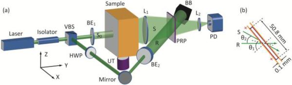
(a) Experimental setup used for the study. BB, beam block; BE1,2, beam expanders; HWP, half-wave plate; L1,2, lenses; PD, photodiode; PRP, photorefractive polymer film; R, reference beam; S0 and S, incident and collected sample beams, respectively; UT, ultrasound transducer; VBS, variable beam splitter, composed of a half-wave plate and a polarizing beam splitter; XYZ, system coordinates. (b) Illustration of beam interference with respect to the PRP in top view.
The advantage of using the large area PRP film in terms of the collection etendue is illustrated in Fig. 2(a) by a comparison with those of other systems, such as CFPI [5, 9], PRC-based interferometers (BSO [4, 7, 10], GaAs [11-13], Sn2P2S6 [14]), and SHB crystals [6, 15], as well as the output etendue of the scattering samples. Each column corresponds to one aforementioned reference. The etendues are estimated by G=πAsin2(Ω/2), where A is the active area and Ω is the emission/acceptance angle of an optical element. The error bar of the scattering samples is from the variation in their output surface dimensions, usually ranging from 40×40 to 100×100 mm2. For PRCs, the error bars originate from the estimated range of Ω (20° to 40° according to [15]), quantified as the angle at which two-wave mixing (TWM) performance drops to ~50% from the maximum.
Fig. 2.

(a) Comparison of etendue. Each column corresponds to one case reported from the references detailed in the text. (b) Comparison of sample beam amplifications.
As seen, although the scattering samples have large output etendues of 5,000-30,000 mm2sr, previous detection schemes had relatively small etendues: CFPIs have small etendues, less than 1 mm2sr, due to their small apertures and narrow acceptance angles; PRCs typically have etendues of 10-30 mm2sr because of fabrication limitations; SHB crystals’ theoretical etendues can be >300 mm2sr, but the practical values only slightly exceed, or are even comparable with, those of the PRCs, due to the small aperture of the cryostat windows. Therefore, to detect tagged light above the noise floor from a thick turbid sample usually requires a rather strong optical illumination onto the sample (e.g., a 2 W continuous beam [7], or a pulsed beam with 1.3 kW peak power [9]). Sometimes, long ultrasound (US) bursts (e.g., 100 cycles at 3.5 MHz [7]) are used to increase the tagged light level, which, however, compromises the imaging resolution along the acoustic axis. In contrast, even with the tilted configuration of light collection, our PRP film yields an etendue as large as ~400 mm2sr, which promises a manifold increase in UOT signal detection sensitivity.
Another important parameter in photorefractive interferometric UOT is the TWM gain exp(ΓL), as the signal is proportional to |exp(ΓL)−1| [4], where Γ is the gain coefficient and L is the photorefractive material thickness along the signal beam’s propagation direction. The real part of Γ is either positive or negative, corresponding to amplification or reduction of the signal beam intensity, which was controlled by the polarity of the DC electric field. The measured TWM amplification of our PRP outperforms those of the BSO crystals in [16] and [7], as compared in Fig. 2(b), leading to a higher sensitivity for tagged light detection.
Taking advantage of the enhanced sensitivity of the PRP-based setup, we imaged absorbing targets embedded in gel-based tissue-mimicking samples of different thicknesses. The composite of the samples consisted of water:gelatin:Intralipid(89:10:1 wt%). Table 1 gives the key operational specifications. The first sample had a transport optical thickness of about 80 lt’. The middle plane of the sample contained three absorbing objects (Obj1-Obj3) spaced at equal intervals (9 mm), as shown in Fig. 3(a). The objects had X-Z dimensions of 2×2.5, 3×3, and 5×5 mm2, respectively, and a thickness of 2 mm in the Y direction. Using two needles embedded in the same plane as reference targets, we aligned the US transducer so that the US focus scanned across the absorbing targets when the sample was translated in the X direction. In the imaging experiment, the sample was scanned at a step size of 0.32 mm, and the photodiode measured the tagged-light signal at each position. Fig. 3(b) is a 2-D image formed from the photodiode signals obtained at each position, normalized by their maximum values. Fig. 3(c) is the 1-D cross-sectional profile along the horizontal dashed line indicated in Fig. 3(b). Obj1 and Obj3 are not fully shown due to the limited scanning range of the translation stage. Three dips in the tagged-light power can be seen on the 1-D profile at positions corresponding to the three absorbers. The estimated lateral resolution, quantified as the distance along the X axis between the points of 75% and 25% contrast of Obj2 (indicated in Fig. 3c), is ~1.6 mm, which approximately matches the ultrasound focal width of ~1.2 mm as defined by its full-width at half-maximum. Fig. 3(d) is a photodiode signal when a 5-cycle US burst propagated through Obj2 along the vertical dashed line indicated in Fig. 3(b). The tagged-light power sensed by the photodiode increased as the US pulse approached its focus, and the power dipped as the pulse reached the absorber. Along the acoustic Z axis, the imaged dimension of Obj2 was 6.6 mm, quantified as the span between 50% and 50% of the contrast peak due to the absorber. The image elongation is reasonable since the detected signal is the convolution of the absorption profile and US amplitude profile in the Z direction.
Table 1. Key parameters of the system.
| Sample 1 | Sample 2 | |
|---|---|---|
| S0 | 140 mW | 870 mW |
| 1-cm diameter | 2.4-cm diameter | |
|
| ||
| R | 70 mW, 3-cm diameter | |
|
| ||
| Ultrasound beam |
2-MHz central frequency |
3.5-MHz central frequency |
| 5 cycles | 10 cycles | |
| 4-MPa peak-peak focal pressure |
2.6-MPa peak-peak focal pressure |
|
| 1-kHz repetition rate | 1-kHz repetition rate | |
|
| ||
| Optical properties |
μa=0.12 cm−1 | μa=0.12 cm−1 |
| μs’=20 cm−1 | μs’=10 cm−1 | |
| 4-cm thick | 9.4-cm thick | |
Fig. 3.

(a) Photograph of the mid-plane of Sample 1. (b) 2-D UOT image of the sample’s mid-plane. (c)(d) Signal profiles along the horizontal and vertical dashed lines in (b), respectively.
To mimic the optical properties of human breast tissue more closely (μs’~10 cm−1), we prepared a second sample having a μs’ of 10 cm−1 and a thickness of 9.4 cm, resulting in a transport optical thickness of 94 lt’. Fig. 4(a) is a photo of its middle plane, containing two absorbing objects (Obj1 and Obj2), and Fig. 4(b) is the obtained 2-D UOT image. Although we used a thicker sample, a higher US frequency, and an expanded sample beam illumination (Table 1), the two absorbing objects are still visible in Fig. 4(b), verifying that our PRP-based system has sufficient sensitivity to image optical contrast from turbid media with thicknesses up to 94 lt’. In comparison, [7] employed a much stronger sample-illuminating beam and longer US bursts to reach the same imaging depth.
Fig. 4.

(a) Photograph of the mid-plane of Sample 2. (b) 2-D UOT image of the sample’s mid-plane.
One major noise source in our measurement was the low-frequency (<1 Hz) TWM gain fluctuation. The PRP performance was susceptible to changes in airflow, vibration, and temperature. Sometimes such environmental noise could result in insufficient SNR, as indicated by the “yellow line” at X~10 mm in Fig. 3(c). Nevertheless, most measurements reasonably detected the tagged photons in our study, assuring the resolving of embedded objects. For in vivo imaging, the current PRP’s slow TWM rise time (~20 s) is not desirable, because the unavoidable movement of a live sample will degrade the TWM performance, and hence the detection sensitivity. Note that the measured TWM rise time is even slower than the previously reported value of ~5 s for the four-wave mixing case [17]. However, recent achievements in the field of PRPs show high promise for faster response [18].
In conclusion, we improved the detection sensitivity in UOT by implementing a large area PRP-based interferometer. The enhancement results from an increased detection etendue and TWM gain. With moderate optical illumination and acoustic applied power, the system can image optical contrasts in tissue-mimicking phantoms with transport optical thicknesses up to 94 lt’, which is equivalent to ~94 mm of breast tissue for light in the red or near-infrared spectral range [7]. The improved sensitivity of the system is an encouraging step towards future clinical applications for UOT.
Acknowledgments
We thank Nitto Denko Technical (@Oceanside, CA) for providing the PRP for this research. This work was sponsored in part by the National Academies Keck Futures Initiative grant IS 13 and National Institute of Health grants DP1 EB016986 (NIH Director’s Pioneer Award), R01 EB000712 and U54 CA136398.
Footnotes
OCIS Codes: 170.3880, 170.6960, 080.2175, 190.7070
Full citation listings
- 1.Wang LV, Jacques SL, Zhao X. Continuous-wave ultrasonic modulation of scattered laser light to image objects in turbid media. Opt. Lett. 1995;20:629–631. doi: 10.1364/ol.20.000629. [DOI] [PubMed] [Google Scholar]
- 2.Kempe M, Larionov M, Zaslavsky D, Genack AZ. Acousto-optic tomography with multiply scattered light. J. Opt. Soc. Am. A. 1997;14:1151–1158. [Google Scholar]
- 3.Leveqe-Fort S, Boccara AC, Lebec M, Saint-Jalmes H. Ultrasonic tagging of photon paths in scattering media: parallel speckle modulation processing. Opt. Lett. 1999;24:181–183. doi: 10.1364/ol.24.000181. [DOI] [PubMed] [Google Scholar]
- 4.Murray TW, Sui L, Maguluri G, Roy RA, Nieva A, Blonigen FJ, DiMarzio CA. Detection of ultrasound-modulated photons in diffuse media using the photorefractive effect. Opt. Lett. 2004;29:2509–2511. doi: 10.1364/ol.29.002509. [DOI] [PubMed] [Google Scholar]
- 5.Sakadzic S, Wang LV. High resolution ultrasound-modulated optical tomography in biological tissues. Opt. Lett. 2004;29:2770–2772. doi: 10.1364/ol.29.002770. [DOI] [PubMed] [Google Scholar]
- 6.Li Y, Hemmer P, Kim C, Zhang H, Wang LV. Detection of ultrasound-modulated diffuse photons using spectral hole burning. Opt. Express. 2008;16:14862–14874. doi: 10.1364/oe.16.014862. [DOI] [PMC free article] [PubMed] [Google Scholar]
- 7.Lai P, Xu X, Wang LV. Ultrasound-modulated optical tomography at new depth. Journal of Biomedical Optics. 2012;17:066006. doi: 10.1117/1.JBO.17.6.066006. [DOI] [PMC free article] [PubMed] [Google Scholar]
- 8.Tay S, Blanche PA, Voorakaranam R, Tunc AV, Lin W, Rokutanda S, Gu T, Flores D, Wang P, Li G, St Hilaire P, Thomas J, Norwood RA, Yamamoto M, Peyghambarian N. An updatable holographic three-dimensional display. Nature. 2008;451:694–698. doi: 10.1038/nature06596. [DOI] [PubMed] [Google Scholar]
- 9.Rousseau G, Blouin A, Monchalin J-P. Ultrasound-modulated optical imaging using a high-power pulsed laser and a double-pass confocal Fabry-Perot interferometer. Opt. Lett. 2009;34:3445–3447. doi: 10.1364/OL.34.003445. [DOI] [PubMed] [Google Scholar]
- 10.Xu X, Zhang H, Hemmer P, Qing D.-k., Kim C, Wang LV. Photorefractive detection of tissue optical and mechanical properties by ultrasound modulated optical tomography. Opt. Lett. 2007;32:656–658. doi: 10.1364/ol.32.000656. [DOI] [PubMed] [Google Scholar]
- 11.Ramaz F, Forget BC, Atlan M, Boccara AC. Photorefractive detection of tagged photons in ultrasound modulated optical tomography of thick biological tissues. Opt. Express. 2004;12:5469–5474. doi: 10.1364/opex.12.005469. [DOI] [PubMed] [Google Scholar]
- 12.Lai P, Roy RA, Murray TW. Quantitative characterization of turbid medium using pressure contrast acousto-optic imaging. Opt. Lett. 2009;34:2850–2852. doi: 10.1364/OL.34.002850. [DOI] [PubMed] [Google Scholar]
- 13.Rousseau G, Blouin A, Monchalin J-P. Ultrasound-modulated optical imaging using a powerful long pulse laser. Opt. Express. 2008;16:12577–12590. doi: 10.1364/oe.16.012577. [DOI] [PubMed] [Google Scholar]
- 14.Farahi S, Montemezzani G, Grabar AA, Huignard JP, Ramaz F. Photorefractive acousto-optic imaging in thick scattering media at 790 nm with a Sn2P2S6:Te crystal. Opt. Lett. 2010;35:1798–1800. doi: 10.1364/OL.35.001798. [DOI] [PubMed] [Google Scholar]
- 15.Zhang H, Sabooni M, Rippe L, Kim C, Kroll S, Wang LV, Hemmer PR. Slow light for deep tissue imaging with ultrasound modulation. Appl. Phys. Lett. 2012;100:131102. doi: 10.1063/1.3696307. [DOI] [PMC free article] [PubMed] [Google Scholar]
- 16.Sui L, Roy RA, Dimarzio CA, Murray TW. Imaging in diffuse media with pulsed-ultrasound-modulated light and the photorefractive effect. Appl. Opt. 2005;44:4041–4048. doi: 10.1364/ao.44.004041. [DOI] [PubMed] [Google Scholar]
- 17.Thomas J, Eralp M, Tay S, Li G, Wang P, Yamamoto M, Schulzgen A, Norwood R, Peyghambarian N. Photorefractive polymers with sub-millisecond response time. Proc. SPIE. 2006:6335. [Google Scholar]
- 18.Suzuki Y, Xu X, Lai P, Wang LV. Energy enhancement in time-reversed ultrasonically encoded optical focusing using a photorefractive polymer. Journal of Biomedical Optics. 2012;17:080507. doi: 10.1117/1.JBO.17.8.080507. [DOI] [PMC free article] [PubMed] [Google Scholar]