Abstract
Purpose
Hip resurfacing arthroplasty (HRA) is a technically demanding operation, requiring both accuracy and precision in placement of the acetabular and femoral components. Malalignment of the component can lead to notching and possible femoral neck fractures. We used specific templates created using a rapid prototyping machine based on the patients’ anatomy, to aid in accurate intraoperative pin placement.
Methods
A 3D model of the hip was reconstructed using spiral computed tomography (CT) data by Amira 3.1 software in 16 patients in whom HRA was planned for hip osteoarthritis (OA). All of the patients in the study had normal contralateral hips. The rotational centre of femoral head on the normal side was superimposed using Imageware12.0 software to determine the centre of the femoral head on the contralateral side. The data was then used to produce patient-specific templates using a rapid prototyping technique. These templates were designed according to the anatomical features of femoral head surface, the rotation centre and the planned prosthesis shaft angle. The orientation of the prosthesis was determined by matching the model to the femoral head surface during the operation. In addition, a control group of 18 patients with OA was operated upon by the conventional method.
Results
The mean prosthesis stem shaft angle (SSA), as determined from postoperative imaging, was 138.68 ± 8.85° for the locating template group, and (118.9 ± 12.8) for the conventional group.
Conclusions
The locating template designed and constructed preoperatively can provide precise and dependable location for hip resurfacing femoral components during arthroplasty and ensure the valgus stem placement necessary for optimal outcomes.
Introduction
Total hip resurfacing arthroplasty is an alternative to total hip replacement for adult patients with hip osteoarthritis (OA). Compared to conventional total hip arthroplasty, the distinct advantages of this procedure include preservation of femoral proximal bone [1, 2], increased range of motion, and low dislocation rates. However, the procedure is technically demanding, and femoral neck fracture is recognised as a primary postoperative complication, secondary to inaccurate placement of the femoral component [3, 4]. In most cases, femoral neck fracture is secondary to varus malpositioning of the component, which leads to notching at the superior aspect of the femoral neck.
Surgeons are in constant pursuit of ways to decrease the rate of this complication. Most biomechanical research and clinical studies have reported that a valgus-oriented prosthesis can decrease the incidence of femoral neck fracture [5, 6]. One hundred and forty degrees valgus placement has been suggested as the ideal placement angle by some authors. At this angle, the prosthesis can completely cover the reamed femoral head and at the same time, avoid notching [7, 8]. However, it is not possible to accurately place the stem in the location determined preoperatively using a freehand technique alone. In the current scenarios, the accuracy of placement depends on experience, intraoperative judgment, and the skill of the operator. Many surgeons have tried using computer navigation to improve the accuracy of the stem placement with variable results [9–11]. The distinctive disadvantage of computer navigation includes increased surgical time, increased cost, and necessity for expensive hardware and software.
Use of rapid prototyping (RP) is a technique that uses additive manufacturing to accurately reconstruct physical objects. RP helps to generate a 3D model based on the inputs from Computed Tomography (CT) or Magnetic Resonance Imaging (MRI) images. It integrates modern numeric control technology, Computer Aided Design/Computer Aided Manufacturing (CAD/CAM) technology, and laser sintering technology to produce the desired surgical simulation models. Within the last two decades, RP has been applied in complex trauma cases, and to design the patient-specific instrumentation for knee replacement [10].
The objective of this study was to evaluate the use of patient-specific templates created using preoperative images and RP technology to perform hip resurfacing arthroplasty, as assessed by the accuracy of femoral stem placement.
Methods
Patients
From February 2007 to December 2011, 34 patients with OA in one hip and normal other side (confirmed on X-ray) formed the study group. The pain on the symptomatic side was severe enough to warrant a hip replacement. Based on previous studies that suggested that the resurfacing procedures were most suitable for patients between 42 and 52 years of age [12, 13] we defined inclusion criteria as patients in the age group of between 37 and 55 years. Patients were divided randomly into two groups according to the inpatient admission number, in which patients with odd or even digits were operated upon with or without the locating template, respectively. Sixteen cases underwent surgery using the locating template. Eighteen cases were treated in the conventional way; these served as the control group for the study. The difference between the two groups was not significant in preoperative evaluation, and both the groups were comparable in terms of age, pathology and other factors. All patients underwent resurfacing arthroplasty over the same time interval and by the same surgeon. This study was approved by the Ethics Committee of First Affiliated Hospital of Henan University of Science and Technology.
Materials
The materials used in the study included software Amira 3.1 (provided by Beijing NCG information Technology Co., Ltd), software UG imageware 12.0 (provided by National Die & Mold CAD Engineering Research Centre; Shanghai Jiaotong Univ.), and SLA Laser shaping machine (provided by Dongguan Banner RP&M Co.,Ltd).
Individualised locating template
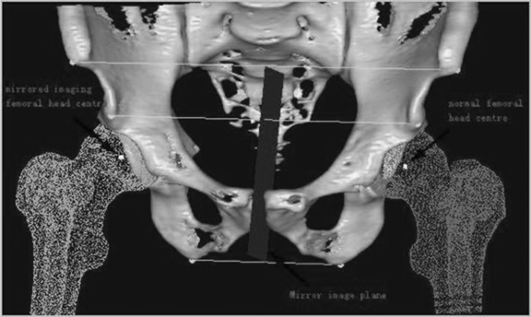
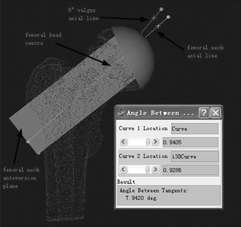
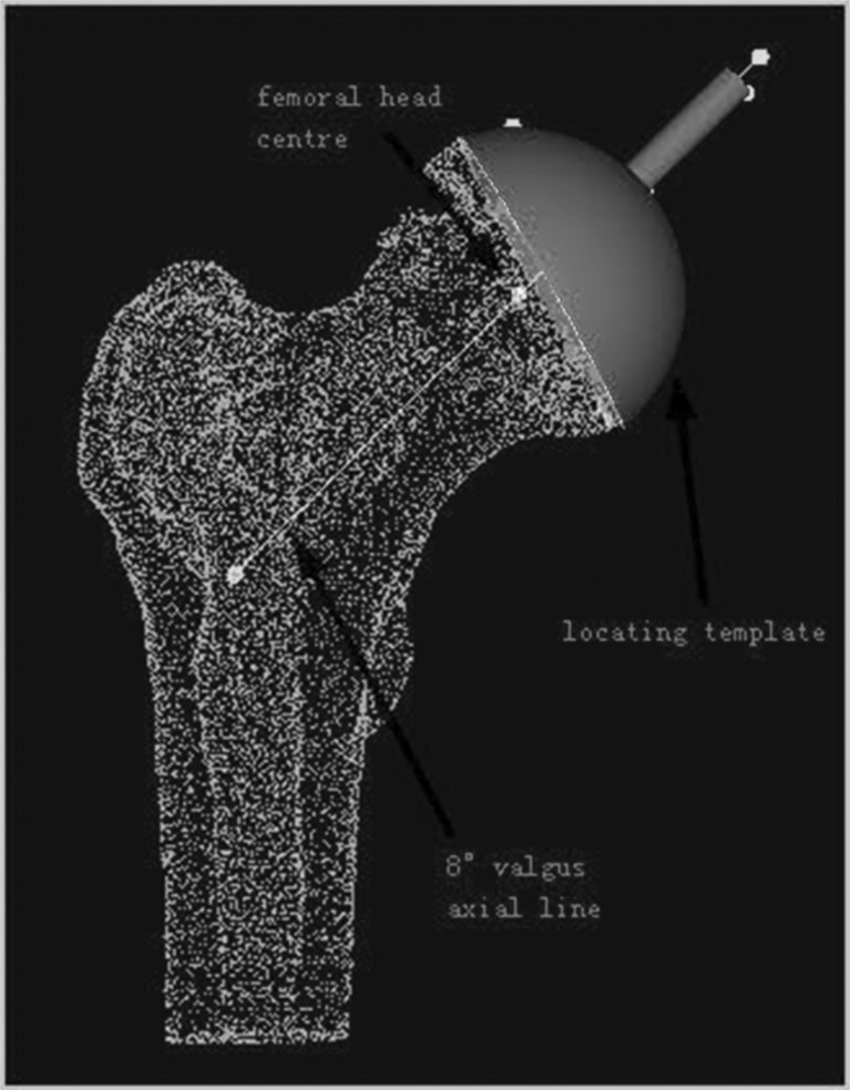
Sixty-four–slice spiral CT scanning data of the hip was collected from 16 patients who underwent operation using the locating template designed by the individual anatomical features of the femoral head surface. Scan parameters were: 120kv, 300mAs. The data were transferred via a DICOM network into a computer workstation. A 3D model hip was reconstructed using Amira 3.1 software, and saved in STL format. Then the 3D model was imported into Imageware12.0 software. The estimated centre of the abnormal hip joint and the central axis of the femoral neck was determined (Fig. 1). The planning involved templating a central axis line that intersected the femoral head centre, as demarcated by a dot. In order to avoid fracture of the femoral neck, several studies have suggested that the axis of the prosthesis should be five to ten degrees of valgus, based on the axial line of normal femoral neck (Fig. 2). The axial line of femoral component (which was the best orientation of the prosthesis) was defined on the above basis. The contours of the locating template were designed according to the surface features of the femoral head and the axial line (Fig. 3). An entity model was produced using the Rapid Prototyping Technology. The orientation of the prosthesis was located by matching the model to the surface of femoral head in the operation.
Fig. 1.
The patient was diagnosed with osteoarthritis in the right hip, and featured a normal left hip. Firstly, depending on the shape of femoral head surface, we fitted the most suitable sphere whose center was considered as the center of normal femoral head. With the aid of a symmetrical osseous symbol, such as anterior superior iliac spine, anterior inferior iliac spine and ischial tuberosity, we ascertained the mirror image plane according to the midpoints of three lines between symmetrical points. The center of abnormal femoral head was determined by the plane
Fig. 2.
According to the anatomical features of 3D femoral neck model by means of software imageware12.1, and depending the shape of femoral neck surface, we fitted the most suitable cylinder whose axis was considered as the axial line of the normal femoral neck. Femoral neck anteversion plane was set by physiological-anatomical features. In the anteversion plane, the femoral neck axial line was rotated 8° in an anti-clockwise direction, by setting the femoral head centre as the centre of a circle. The rotated line was considered as the axial line of the femoral component
Fig. 3.
The contour of the locating template was designed according to the surface features of femoral head and the setting axial line of femoral component
Surgical technique
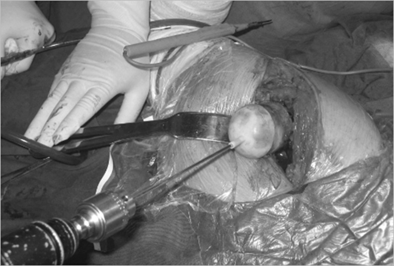
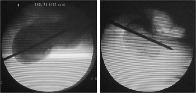
The senior author performed all of the operations using a posterolateral approach. A standard operating procedure for resurfacing arthroplasty was followed in every case. When the femoral head was dislocated and exposed, the locating template was matched to the surface of the femoral head in the best possible manner. A Kirschner wire was inserted into the femoral neck, according to the template (Fig. 4). We evaluated the axial location of femoral component (shown by K-wire) with anteroposterior (A-P) and axial projection images of the femoral neck during the operation via a C-arm machine to ensure correct positioning of the wire (Fig. 5).
Fig. 4.
The locating template was matched to surface of femoral head as well as possible. A Kirschner wire was inserted into femoral neck according to the template
Fig. 5.
The location of the wire was correct, shown with A-P and lateral position images by C-arm machine
Statistical analysis
Statistical analysis in this study was performed by using a two-sample T-test (SPSS13.0; provided by statistics faculty working office of Henan University of Science and Technology). The level of significance was defined as P values < 0.05 with 95 % confidence intervals, and all statistical tests were two sided.
Results
Radiographic evaluation
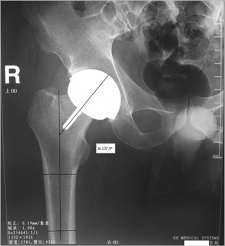
All patients underwent postoperative radiography between seven and ten days postoperatively. In order to obtain relatively accurate data, all efforts were made to decrease the error that usually occurs during radiography. There are concerns regarding the angle of projection and the position of the patient when X-rays are used to evaluate implant positioning. Standard positive photographs of the hip joint were taken, which required projecting a line vertical to the hip joint centre. Patients were placed in the supine position, with the limb at 10–15° of internal rotation to ensure that the patella was facing upwards. In A-P radiographs, the stem-shaft angle was measured between the axial line of femur and the extension line of component stem, with the measuring tool of software Adobe Photoshop (Fig. 6). Measured data was displayed in Table 1.
Fig. 6.
The stem-shaft angle was 137.9° by measuring postoperative X-ray photographs
Table 1.
Comparison in stem-shaft angle between group 1 (the locating template) and group 2 (conventional surgery)
| Stem-shaft angle of different patients(unit: °) | Mean±SD | t | P | |||||||||
|---|---|---|---|---|---|---|---|---|---|---|---|---|
| Group 1 | 143 | 131 | 138 | 135 | 148 | 132 | 140 | 149 | 136.69 ± 7.70 | −4.786 | 0.001 | |
| (n = 16) | 125 | 128 | 134 | 123 | 139 | 136 | 145 | 141 | ||||
| Group 2 | 117 | 145 | 120 | 106 | 114 | 121 | 108 | 124 | 115 | 121.22 ± 10.69 | ||
| (n = 18) | 137 | 129 | 118 | 130 | 132 | 122 | 103 | 119 | 122 | |||
Statistical methods
There were obvious differences between the two groups with regard to femoral component stem-shaft angles. Each radiograph was evaluated by two authors. The mean stem-shaft angle was 136.69° (range, 123° to 149°) for the locating template group and 121.22° (range, 103° to 145°) for the conventional surgical group (p = 0.001).
Discussion
There is a growing trend towards the use of hip resurfacing implants in younger active patients, because of its superiority over the conventional total hip replacement in terms of greater range of motion and bone stock preservation. One of the key elements for the success of hip resurfacing is optimal placement of the femoral stem in all planes. Our study was conducted to evaluate the use of patient-specific templates as an aid to accurate placement of the femoral prosthesis component. Patient-specific templates were manufactured on the basis of the patient’s CT scan data, and using rapid prototyping (RP) technology.
Recent studies have disclosed that valgus alignment is preferable to varus alignment during resurfacing hip arthroplasty. Anglin et al. performed a cadaver study to investigate the effect of neutral or valgus placement of the femoral component. The result showed that 10° valgus placement increased load by an average of 28 % over neutral placement with normal bone mineral density. They recommend that placement of the femoral component should be in valgus [14]. Finite element analysis studies have also demonstrated that placing the implant in a valgus orientation can reduce the local stresses and strains associated with implant loosening and neck fracture [3]. Mont et al. assessed a large amount of clinical data indicated that a 140° ± 5° stem-shaft angle was superior to normal femoral-neck-shaft angle in overall complication rates [6]. Clinical data has shown that a varus angle of over five degrees of the component stem compared with the preoperative femoral neck-shaft angle occurred in 71 % cases of the hips that fractured [4]. However, the valgus placement should be optimal and not excessive; otherwise, in situations where the valgus angle is more than 140°, notching and incomplete coverage of the reamed femoral head usually occurs [7, 8]. Therefore, the target of the operation is obtaining the maximum possible valgus angle, while avoiding notching.
It is critical to define the location of the femoral component. Amstutz et al. summarised results from 600 cases that underwent metal-on-metal surface arthroplasties between 1996 and 2003. By analysing the collected data, he recommended a stem-shaft angle of 140° [8]. Previous research indicated that if the stem-shaft angle was more than 10° valgus, a greater likelihood of notching would occur [14]. With awareness of different anatomical features in different races, on the basis of the results reported by experts, we considered it desirable that 5°–10° valgus could be considered as the best orientation for the component.
The background of the research carried out in this article was based on our desire to find the solution to ensure an accurate placement of the component. The placement is usually influenced by subjective and objective factors, such as operative technique, individual experience, patients’ body position, surgical locating instruments, and so on. At present, with the development of computer technology, computer-assisted surgery has been introduced into hip resurfacing arthroplasty. The most favourable benefit of computer-assisted navigation is the ability it provides the surgeons, in terms of performing the operation as accurately as possible [15, 16]. Cobb et al. performed an experiment in which 20 students were divided in three groups and were asked to determine the location of femoral component with three different measures, including conventional instrumentation, a CT-based planner, and a navigation system. Data suggested navigation played an important role in obtaining a high degree of accuracy [9]. Hart et al. evaluated the accuracy of conventional and computer-assisted femoral component implantation in surface arthroplasty by analysing standard radiographs. Obviously, The navigation system is preferable to conventional orientation [17–20]. Similar theoretical and experimental evidence regarding the benefit of computer-assisted navigation have also been reported [21, 22]. However, computer navigation suffers from its own distinctive disadvantages, mainly a significant learning curve, increased operative time [23] and expensive hardware and software. In this study, we designed the individualised digital template according to spiral CT data by means of software Amira4.1 and Imageware 12.1. An Entity model was produced by Rapid Prototyping Technology. These procedures were completed before operation, and the model was applied intraoperatively by matching it to the surface of the femoral head. The benefits of this method include accurate placement of the component, decreasing operative time, easy intraoperative handling, reduced instrumentation, and a relatively decreased learning curve for beginners, which has been a factor in the rate of femoral neck fracture [24].
There are a number of limitations to this study as well as the described technology. Firstly, using the software Amira4.1 and Imageware12.1 may be technically challenging for orthopaedic surgeons, and they may need help from external technicians. We consider it necessary to establish a technical workstation and website to offer support to these surgeons. Also, the rapid prototyping machine is very expensive; however, since it has multiple uses, and is available in many industrial design and production units, a close coordination with these units is essential. Finally, our study is limited by the relatively small patient population; therefore, the effect of this method should be verified using more cases. We intend to publish a larger case series with an increased enrollment in the future.
In conclusion, we found that the application of designed individualised locating template hip resurfacing can lead to a high degree of accuracy of femoral component placement in hip resurfacing arthroplasty. Our study suggests that this measure could represent a promising means for resident education and beginners learning this procedure.
References
- 1.Ball ST, Le Duff MJ, Amstutz HC. Early results of conversion of a failed femoral component in hip resurfacing arthroplasty. J Bone Joint Surg Am. 2007;89(4):735–741. doi: 10.2106/JBJS.F.00708. [DOI] [PubMed] [Google Scholar]
- 2.Kishida Y, Sugano N, Nishii T, Miki H, Yamaguchi K, Yoshikawa H. Preservation of the bone mineral density of the femur after surface replacement of the hip. J Bone Joint Surg Br. 2004;86(2):185–189. doi: 10.1302/0301-620X.86B2.14338. [DOI] [PubMed] [Google Scholar]
- 3.Long JP, Bartel DL. Surgical variables affect the mechanics of a hip resurfacing system. Clin Orthop Relat Res. 2006;453:115–122. doi: 10.1097/01.blo.0000238873.09390.6f. [DOI] [PubMed] [Google Scholar]
- 4.Shimmin AJ, Back D. Femoral neck fractures following Birmingham hip resurfacing: a national review of 50 cases. J Bone Joint Surg Br. 2005;87(4):463–464. doi: 10.1302/0301-620X.87B4.15498. [DOI] [PubMed] [Google Scholar]
- 5.Back DL, Dalziel R, Young D, Shimmin A. Early results of primary Birmingham hip resurfacings. An independent prospective study of the first 230 hips. J Bone Joint Surg Br. 2005;87(3):324–329. doi: 10.1302/0301-620X.87B3.15556. [DOI] [PubMed] [Google Scholar]
- 6.Mont MA, Seyler TM, Ulrich SD, Beaule PE, Boyd HS, Grecula MJ, Goldberg VM, Kennedy WR, Marker DR, Schmalzried TP, Sparling EA, Vail TP, Amstutz HC. Effect of changing indications and techniques on total hip resurfacing. Clin Orthop Relat Res. 2007;465:63–70. doi: 10.1097/BLO.0b013e318159dd60. [DOI] [PubMed] [Google Scholar]
- 7.Amstutz HC, Beaule PE, Dorey FJ, Le Duff MJ, Campbell PA, Gruen TA. Metal-on-metal hybrid surface arthroplasty: two to six-year follow-up study. J Bone Joint Surg Am. 2004;86-A(1):28–39. [PubMed] [Google Scholar]
- 8.Amstutz HC, Campbell PA, Le Duff MJ. Fracture of the neck of the femur after surface arthroplasty of the hip. J Bone Joint Surg Am. 2004;86-A(9):1874–1877. doi: 10.2106/00004623-200409000-00003. [DOI] [PubMed] [Google Scholar]
- 9.Cobb JP, Kannan V, Brust K, Thevendran G. Navigation reduces the learning curve in resurfacing total hip arthroplasty. Clin Orthop Relat Res. 2007;463:90–97. doi: 10.1097/BLO.0b013e318126c0a5. [DOI] [PubMed] [Google Scholar]
- 10.Hart R, Svab P, Filan P. Intraoperative navigation in hip surface arthroplasty: a radiographic comparative analysis study. Arch Orthop Trauma Surg. 2008;128(4):429–434. doi: 10.1007/s00402-007-0540-3. [DOI] [PubMed] [Google Scholar]
- 11.Hodgson AJ, Inkpen KB, Shekhman M, Anglin C, Tonetti J, Masri BA, Duncan CP, Garbuz DS, Greidanus NV. Computer-assisted femoral head resurfacing. Comput Aided Surg. 2005;10(5–6):337–343. doi: 10.3109/10929080500379440. [DOI] [PubMed] [Google Scholar]
- 12.Nishii T, Sugano N, Miki H, Takao M, Koyama T, Yoshikawa H. Five-year results of metal-on-metal resurfacing arthroplasty in Asian patients. J Arthroplasty. 2007;22(2):176–183. doi: 10.1016/j.arth.2006.04.008. [DOI] [PubMed] [Google Scholar]
- 13.Witzleb WC, Arnold M, Krummenauer F, Knecht A, Ranisch H, Gunther KP. Birmingham hip resurfacing arthroplasty: short-term clinical and radiographic outcome. Eur J Med Res. 2008;13(1):39–46. [PubMed] [Google Scholar]
- 14.Anglin C, Masri BA, Tonetti J, Hodgson AJ, Greidanus NV. Hip resurfacing femoral neck fracture influenced by valgus placement. Clin Orthop Relat Res. 2007;465:71–79. doi: 10.1097/BLO.0b013e318137a13f. [DOI] [PubMed] [Google Scholar]
- 15.Ulrich SD, Bonutti PM, Seyler TM, Marker DR, Jones LC, Mont MA. Outcomes-based evaluations supporting computer-assisted surgery and minimally invasive surgery for total hip arthroplasty. Expert Rev Med Devices. 2007;4(6):873–883. doi: 10.1586/17434440.4.6.873. [DOI] [PubMed] [Google Scholar]
- 16.Pitto RP, Malak S, Anderson IA. Accuracy of a computer-assisted navigation system in resurfacing hip arthroplasty. Int Orthop. 2009;33(2):391–395. doi: 10.1007/s00264-008-0644-6. [DOI] [PMC free article] [PubMed] [Google Scholar]
- 17.Bagaria V, Deshpande S, Rasalkar DD, Kuthe A, Paunipagar BK. Use of rapid prototyping and three-dimensional reconstruction modeling in the management of complex fractures. Eur J Radiol. 2011;80(3):814–820. doi: 10.1016/j.ejrad.2010.10.007. [DOI] [PubMed] [Google Scholar]
- 18.Brown GA, Firoozbakhsh K, DeCoster TA, Reyna JR, Jr, Moneim M. Rapid prototyping: the future of trauma surgery? J Bone Joint Surg Am. 2003;85-A(Suppl 4):49–55. [PubMed] [Google Scholar]
- 19.Chaware SM, Bagaria V, Kuthe A. Application of the rapid prototyping technique to design a customized temporomandibular joint used to treat temporomandibular ankylosis. Indian J Plast Surg. 2009;42(1):85–93. doi: 10.4103/0970-0358.53016. [DOI] [PMC free article] [PubMed] [Google Scholar]
- 20.Radermacher K, Portheine F, Anton M, Zimolong A, Kaspers G, Rau G, Staudte HW. Computer assisted orthopaedic surgery with image based individual templates. Clin Orthop Relat Res. 1998;354:28–38. doi: 10.1097/00003086-199809000-00005. [DOI] [PubMed] [Google Scholar]
- 21.Belei P, Skwara A, De La Fuente M, Schkommodau E, Fuchs S, Wirtz DC, Kamper C, Radermacher K. Fluoroscopic navigation system for hip surface replacement. Comput Aided Surg. 2007;12(3):160–167. doi: 10.3109/10929080701336207. [DOI] [PubMed] [Google Scholar]
- 22.Hodgson A, Helmy N, Masri BA, Greidanus NV, Inkpen KB, Duncan CP, Garbuz DS, Anglin C. Comparative repeatability of guide-pin axis positioning in computer-assisted and manual femoral head resurfacing arthroplasty. Proc Inst Mech Eng H. 2007;221(7):713–724. doi: 10.1243/09544119JEIM284. [DOI] [PubMed] [Google Scholar]
- 23.Schnurr C, Michael JW, Eysel P, Konig DP. Imageless navigation of hip resurfacing arthroplasty increases the implant accuracy. Int Orthop. 2009;33(2):365–372. doi: 10.1007/s00264-007-0494-7. [DOI] [PMC free article] [PubMed] [Google Scholar]
- 24.Marker DR, Seyler TM, Jinnah RH, Delanois RE, Ulrich SD, Mont MA. Femoral neck fractures after metal-on-metal total hip resurfacing: a prospective cohort study. J Arthroplasty. 2007;22(7 Suppl 3):66–71. doi: 10.1016/j.arth.2007.05.017. [DOI] [PubMed] [Google Scholar]


