Abstract
The field of tissue engineering and drug delivery calls for new measurement tools, non-invasive real-time assays, and design methods for the next wave of innovations. Based on our recent progress in developing intrinsically biodegradable photoluminescent polymers (BPLPs) without conjugating organic dyes or quantum dots, in this paper, we developed a new type urethane-doped biodegradable photoluminescent polymers (UBPLPs) that could potentially serve as a new tool to respond the above call for innovations. Inherited from BPLPs, UBPLPs demonstrated strong inherent photoluminescence and excellent cytocompatibility in vitro. Crosslinked UBPLPs (CUBPLPs) showed soft, elastic, but strong mechanical properties with a tensile strength as high as 49.41±6.17 MPa and a corresponding elongation at break of 334.87±26.31%. Porous triphasic CUBPLP vascular scaffolds showed a burst pressure of 769.33±70.88 mmHg and a suture retention strength of 1.79±0.11 N. Stable but photoluminescent nanoparticles with average size of 103 nm were also obtained by nanoprecipitation. High loading efficiency (91.84%) and sustained release of 5-fluorouracil (up to 120 h) were achieved from UBPLP nanoparticles. With a quantum yield as high as 38.65%, both triphasic scaffold and nanoparticle solutions could be non-invasively detected in vivo. UBPLPs represent an innovation in fluorescent biomaterial design and may offer great potential in advancing the field of tissue engineering and drug delivery where bioimaging has gained increasing interest.
Keywords: Photoluminescence, Biodegradable, Elastomer, Tissue Engineering, Drug Delivery
1. Introduction
During the last two decades, biodegradable polymers have become the most studied biomaterials for many biomedical applications such as tissue engineering, drug delivery, and bioimaging [1–4]. Using biodegradable polymers as implant materials is beneficial as the implants may be degraded leaving no foreign materials behind and cleared by the body once their missions are complete,. A large number of biodegradable polymers have been studied for various biomedical applications. FDA approved biodegradable polylactone polymers, such as poly (L-lactic acid) (PLLA) and poly (glycolic acid) (PGA), and their copolymers, are among the most studied polymers in tissue engineering and drug delivery due to their controlled degradation and excellent biocompatibility [3, 5–7]. Aspired by mimicking the mechanical properties of soft tissues in tissue engineering, soft and elastomeric biodegradable crosslinking polyesters, such as poly (octamethylene citrates) (POC) and poly (glycerol sebacate) (PGS), have recently been developed [8, 9]. Although soft and elastic, the quick loss of mechanical strength when fabricated into porous scaffolds renders these materials incapable of creating immediately suturable off-the-shelf tissue scaffolds. In a previous report on the development of crosslinked urethane-doped polyesters (CUPE), we have shown that chemically doping urethane/urea bonds into crosslinked polyester network polymers can significantly increase tensile strength strength of POC from 6.7 MPa to 33.35 MPa [10]. Along with its excellent hemocompatibility, the high mechanical strength of CUPE provided sufficient room for mechanical loss due to scaffold fabrication or in wet physiological environment and suggests that CUPE may serve as an ideal candidate for vascular tissue engineering [11, 12].
Recently, there has been increasing attention on developing biodegradable materials with fluorescent properties. For example, non-invasive fluorescence imaging was used to assess the in vivo degradation of scaffolds decorated with fluorescent moieties [13, 14]. Such real-time in-situ measurements in the design of biomaterials with desired degradability provides a more accurate estimation of the scaffold/material degradation in vivo, which was considered more instrumental than the empirical estimation from the usual in vitro degradation study conducted in PBS. For drug delivery, biodegradable polymeric nanoparticles equipped with fluorescent moieties resulted in theranostic devices for more effective disease management such as cancer diagnosis and treatment. Traditionally, organic dyes or semiconducting quantum dots are incorporated to enable fluorescence [15, 16]. Although promising, organic dyes, such as Indocyanine Green (ICG) and fluorescein, have proved to be cytotoxic at the cellular level, and have low dye-to-reporter molecule labeling ratios [17]. Quantum dots have been extensively studied in fluorescent-based biological applications such as in vitro cellular labeling and in vivo cancer labeling. However, toxicity from the heavy metal content evoked great concern in biomedical applications [18]. Green fluorescent protein (GFP) has attracted tremendous attention for its unique intrinsic fluorescence. However, it suffers from photobleaching, instability, and may cause cellular toxicity due to aggregation inside the cells [19]. In addition, conjugating or encapsulating the above fluorescent agents into biodegradable polymers adds complexity to the system such as the increased particle sizes, insufficient dye-to-polymer ratios, incorporation of toxic chemicals used in conjugation, and additional purification process needed, etc. Nonetheless, the above-mentioned fluorescent agents are ancillary to implant materials serving as imaging probes only. Developing biodegradable polymers with intrinsic photoluminescent properties has been a challenge. Recently, progress has been made in the authors’ lab in developing biodegradable photoluminescent polymers (BPLPs) which showed intriguing photoluminescent properties such as tunable intrinsic fluorescence emission (up to 725 nm) and high quantum yield (up to 62.33%) without incorporating any additional organic dyes or quantum dots [20]. BPLPs could be fabricated into soft and elastomeric films, porous scaffolds, and micro/nanoparticles without losing fluorescent properties.
The intrinsic photoluminescent properties make BPLPs promising materials for tissue engineering and drug delivery. However, the tensile strength of crosslinked BPLPs (6.5 ± 0.8 MPa tensile strength) is not high enough for vascular tissue engineering similar to POC as described earlier. Fabricating BPLPs into nanoparticles could also be problematic as the sticky nature of the low molecular weight of BPLPs makes the nanoparticles prone to aggregation. Given the considerable interests in developing mechanically strong biodegradable elastomers and fluorescence imaging enabled implant materials in tissue engineering and drug delivery, herein, we report a new family of urethane-doped biodegradable photoluminescent polymers (UBPLPs) to address the above challenges. The rational behind UBPLP syntheses is to dope urethane or urea bonds in BPLP to significantly enhance the mechanical strength similar to the doping of urethane/urea bonds in POC to improve mechanical strength while retaining the intriguing photoluminescent properties of BPLPs in the resulting UBPLPs. The chemical and physical (mechanical and optical) properties and cytocompatibility of UBPLPs and their crosslinked polymer (CUBPLPs) were fully characterized. Triphasic vascular grafts that meet the off-the-shelf mechanical requirements and theranostic nanoparticles were fabricated and characterized in vitro and in vivo to demonstrate the potentials of fluorescence-enabled UBPLPs in tissue engineering and cancer drug delivery.
2. Materials and Methods
All chemicals, cell culture medium, and supplements were purchased from Sigma-Aldrich (St. Louis, MO), except where mentioned otherwise. All chemicals were used as received.
2.1. UBPLP Synthesis
UBPLP pre-polymers were synthesized in two steps (Figure 1A). Step one involves the synthesis of a BPLP pre-polymer according to our previously published methods [20]. Briefly, BPLP was first synthesized by reacting 1.0:1.1:0.2 monomer ratios of citric acid, 1,8- octanediol, and L-Cysteine, respectively, in a three-necked round bottom flask fitted with an inlet and outlet adapter at 160°C under a constant flow of nitrogen. Once all the monomers had melted, the temperature of the system was lowered to 140°C, and the reaction was allowed to continue for 2h to create the BPLP pre-polymer. The obtained pre-polymer was then purified by drop-wise precipitation in deionized water. The precipitated pre-polymer was collected and lyophilized for 24 h to obtain the purified BPLP pre-polymer.
Figure 1.
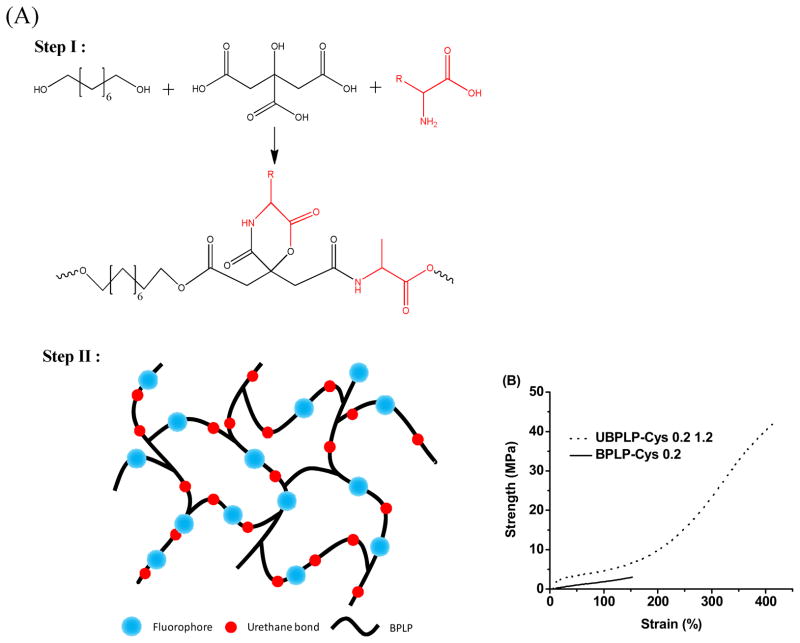
(A) Synthesis schematic of UBPLP polymers. BPLPs were synthesized via condensation polymerization in Step 1. In Step 2, 1,6-hexamethyl was used to extend the BPLPs chain. (B) Tensile Stress-Strain curves of crosslinked UBPLP-Cys 1.2 and BPLP-Cys.
In the second step, the BPLP pre-polymer was used as precursor to react with 1,6-hexamethyl diisocyanate (HDI) to obtain UBPLP. Briefly, BPLP was dissolved in 1,4-dioxane (3% w/v) in a clean reaction flask, and HDI was then added to the BPLP solution under constant stirring at 55 °C using stannous octoate as a catalyst (0.1% w/v). UBPLP pre-polymers were synthesized using various feeding molar ratios of BPLP:HDI (1.0:0.9, and 1.0:1.2), and different BPLP pre-polymer precursors (BPLP reacted with cysteine or serine), which are referred to as UBPLP-Cys 0.9, UBPLP-Cys 1.2, UBPLP-Ser 0.9, and UBPLP-Ser 1.2. The reaction was terminated upon the disappearance of the isocyanate peak located at 2267 cm−1, which was determined by FT-IR analysis. The resulting UBPLP was post-polymerized in an oven maintained at 80 ºC for pre-determined time periods to obtain crosslinked urethane-doped BPLP (CUBPLP).
2.2. Photoluminescent Property
Photoluminescence spectra of UBPLP solutions were acquired on a Shimadzu RF-5301 PC fluorospectrophotometer. All samples were set to concentration of 3% (w/v). Both the excitation and the emission slit widths were set at 1.5 nm for all samples unless otherwise stated. The emission spectra of UBPLP-Cys and UBPLP-Ser were recorded under same circumstance using different excitation wavelengths. The Williams method was used to measure the fluorescent quantum yield of the BPLP polymers [21]. Briefly, all UBPLP solutions were diluted with 1,4-dioxane to a final concentration of 1%. The quantum yield of all samples was measured in 1,4-dioxane unless noticed otherwise. The solution was scanned at various excitation wavelengths. Optimal excitation wavelength was determined as the spectrum that generated the highest emission intensity. Next, the UV-vis absorbance spectrum was collected with the same solution and the absorbance at the optimal excitation wavelength was noted. Next, a series of solutions was prepared with gradient concentrations, so that the absorbance of the each solution was within the range of 0.01–0.1 Abs units. The fluorescence spectrum was also collected for the same solution in the 10 mm fluorescence cuvette. The fluorescence intensity, which is the area of the fluorescence spectrum, was calculated and noted. Five solutions with different concentrations were tested and the graphs of integrated fluorescence intensity vs. absorbance were plotted. The quantum yields of the BPLP polymers were calculated according to following equation:
where, Φ = quantum yield; Slope = gradient of the curve obtained from the plot of intensity versus absorbance; η Refractive index of the solvent; × = subscript to denote the sample, and ST = subscript to denote the standard. Anthracene, a commercially available organic dye with a quantum yield of 0.27, was used as a standard in ethanol.
2.3. In Vitro Degradation
In vitro degradation studies were conducted in both phosphate buffered saline (PBS, pH=7.4) and NaOH solutions (0.01M). NaOH degradation was used to screen the polymer degradation in a short period of time. The polymer films were cut into 7 mm disc using a cork borer. The initial weight of the samples was noted as W1. The samples were placed in test tubes containing 10 ml degradation fluids and incubated at 37 °C for the period of study. At pre-determined time points, the samples were removed and washed thoroughly with deionized water (3 times) to remove any residual salt or base. The samples were then lyophilized for 3d to remove traces of water and weighted as W2. Degradation was determined as (W1-W2)/W1 × 100%.
2.4. Triphasic Graft Fabrication
Multi-phasic small diameter vascular grafts were fabricated to replicate the stratified architecture of native vessels. Briefly, 3 mm outer diameter steel rods were dip coated with a pre-polymer solution (3% w/v) in 1,4-dioxane, and coated with NaCl (99% purity) with an average size of 1–20 μm. Next, NaCl with an average size of 1–20 um was mixed with a pre-polymer solution in a 1:5 polymer to salt weight ratio, and mixed until a viscous paste was formed. The paste was then transferred onto the steel rods to create a 200 μm thick layer. Next, NaCl with an average size of 150–250 μm was mixed with a pre-polymer solution in a 1:10 polymer to salt ratio, and mixed until a viscous paste was formed. The paste was then transferred over the previous layer to create an 800 μm thick layer. The steel rods were placed in a laminar flow hood overnight, and then transferred to an oven maintained at 80 °C for 4 days for crosslinking. After polymer crosslinking, the rod/material assembly was immersed in deionized water with complete water changes every 6 hours. The complete removal of NaCl was determined by silver nitrate. The resulting vascular grafts were removed from the rod and dried using lyophilization. Graft morphology was examined by scanning electron microscopy (SEM) (Hitachi S-3000N, Hitachi Science System, Ibaaki, Japan).
2.5. Mechanical Tests
Tensile testing, suture retention, and burst pressure were carried out on the triphasic scaffolds. All mechanical testing was carried out on a MTS Insight2 mechanical tester (MTS System, Minneapolis, MN) fitted with a 10N load cell (Model 569326-02, MTS System, Minneapolis, MN). A sample size of n=5 was used for all the following tests.
For tensile tests, the triphasic scaffolds were cut into rectangular strips and their dimensions were recorded using a digital caliper. The samples were pulled at a rate of 500 mm/min and elongated to failure. Values were converted to stress-strain curves and the initial modulus was calculated from the initial gradient of the resulting curves (0–10% elongation). The results are presented as the means ± standard deviation. For suture retention, the scaffolds were cut into rectangular specimens with 15 × 6 mm (length × width) dimensions. At 2 mm from the short edge of the rectangular segment, a Prolene 5-0 suture (Ethicon) was inserted and tied to form a loop. One set of clamps of the tensile tester was used to secure the sample and the second set was used to clamp and pull the looped suture at a deflection rate of 2 mm/s, until scaffold rupture occurred. The peak load recorded was reported as the suture retention strength. Burst pressure of triphasic graft was evaluated using a previously described technique [22]. Briefly, one end of the graft was connected to a digital pressure gauge (VWR International) and the other end was connected to a 60 mL syringe. The syringe was filled with PBS and mounted on an Infusion/Withdrawal pump (Harvard Apparatus, Millis, MA) that had been pre-programmed with an output rate of 0.67 mL/min. The burst pressure was recorded as the maximum pressure measured by the gauge before the graft burst.
2.6. Nanoparticle Fabrication and Drug Release
UBPLPs nanoparticles were prepared using a nanoprecipitation technique. To prepare polymer solutions for nanoprecipitation, UBPLPs were synthesized in tetrahydrofuran (THF) instead of 1,4-dioxane. The concentration of final solution was finalized to 3% (w/v). 10 mL of the polymer solution was added dropwise into 20 ml of deionized water/PBS under magnetic stirring at a speed of about 400 rpm. The setup was left overnight in a chemical hood to allow the acetone to evaporate. The resulting particle size was measured by Dynamic Light Scattering (DLS, Microtrack). The particle morphology of nanoparticles was observed by transmission electron microscope (TEM).
For drug release, 5-fluouracil (5F) was loaded into nanoparticles using two formulae. Formula A: 0.01g 5F was dissolved in 10 mL UBPLPs polymer solution in THF with gentle heating in a sealed glass tube. The mixture was added drop wise into 20 mL of PBS to obtain 5F-loaded UBPLP nanoparticles. Formula B: 10 mL UBPLP THF solution was added drop wise into 20 mL PBS with pre-dissolved 0.01g 5F. Solutions from both formulae were stirred overnight in a chemical hood to let the THF evaporate. To determine the drug loading efficiency, 1mL of the 5F-loaded nanoparticle solution was diluted in PBS to make a final volume of 20 mL. The diluted nanoparticle solution was ultra-centrifuged, and the absorbance of supernatant was examined by Infinite200 microplate reader (Tecan Group Ltd., Switzerland) at 270 nm. The loading efficiency was calculated using following equation:
The in vitro drug release study was performed in a sealed glass beaker with 100 mL phosphate buffer saline (PBS, pH 7.4) at 37 °C. 5F-loaded UBPLP nanoparticles from each formula were placed in a dialysis bag (Mw cut-off of 1000 Da). The dialysis bag was then immersed in the release medium and kept in a horizontal laboratory shaker at a constant temperature (37 °C) and stirring (100 rpm). To measure the drug release content, samples (1 mL) were removed periodically and replaced by fresh PBS. The amount of released 5F was analyzed with a microplate reader at 270 nm. Five samples were measured to obtain the averages at each time point.
2.7. Cytotoxicity
Cytotoxicity of UBPLP was evaluated in vitro by seeding the crosslinked UBPLP films with the NIH 3T3 fibroblasts (ATCC). The cell proliferation was performed using Methylthiazoletetrazolium (MTT) cell proliferation and viability assay kit. A PLGA (25/75) film was used as control. All testing films were cut into circular discs (7mm in diameter) and sterilized in 70% ethanol for 3h followed by another 30 min of UV light exposure in 96-well plates. The cells were cultured in Dulbecco’s modified eagle’s medium (DMEM) supplemented with 10% fetal bovine serum (FBS) and 1% penicillin streptomycin. The culture flasks were maintained in an incubator at 37 °C, 5% CO2 and 95% relative humidity. The cell seeding density was 1 × 10⁵ cells/mL per well. MTT assay analysis was performed at 1, 3, and 7 days of culture as per the manufacturer’s protocol. Absorbance was analyzed with an Infinite200 microplate reader (Tecan Group Ltd., Switzerland) at 570 nm, with a reference wavelength of 690 nm within 30 min of MTT solvent addition.
2.8. In Vivo Fluorescence Signaling
For nanoparticle/scaffold bioimaging in vivo, UBPLP-Ser 1.2 nanoparticles (2% wt. in PBS, 80 nm in diameter, sterilized by filtering through a syringe filter (0.22 μm) and CUBPLPs triphasic scaffolds (3 mm of inner diameter, 2 mm of wall thickness, and 5 mm in length, sterilized by 70% ethanol and UV light) were injected/implanted subcutaneously in Black mice (C57BL/6 J). The mice were then imaged using a KODAK In-Vivo FX Pro system (Carestream Health, Rochester, NY) immediately after the implantation as described previously [20]. Animals were cared for in compliance with the regulations of the animal care and use committee of The University of Texas at Arlington.
3. Results and Discussions
In our previous studies, crosslinked BPLPs (CBPLPs) showed soft and elastic mechanical properties and excellent biocompatibility, which are promising for soft tissue engineering [20]. However, the significant loss of mechanical strength upon scaffold fabrication reduces its potential for cardiovascular tissue engineering. BPLPs could also be easily fabricated into nanoparticles through a nano-precipitation method. However, BPLP nanoparticles tend to aggregate due to the sticky nature of the low molecular weight BPLPs, which makes them difficult to be exploited as theranostic probes. A higher molecular weight and stronger mechanical properties needed to be achieved to address the above issues. Fortunately, we have previously developed a urethane-doping strategy to significantly improve the molecular weight of pre-POC and the mechanical properties of the crosslinked POC by reacting pre-POC with diisocyanate followed by thermally crosslinking into CUPE [10]. We expect that the same strategy can be applied to BPLP synthesis to yield higher molecular weight of BPLP pre-polymers resulting in mechanically strong crosslinked urethane-doped BPLPs. The mild reaction condition and specificity of isocyanate chemistry will only consume hydroxyl and carboxylic groups without affecting the photoluminescent properties of the polymers. Along with chain extension through isocyanate chemistry, the consumption of functional groups will also reduce the sticky nature, thus increasing the stability of nanoparticles.
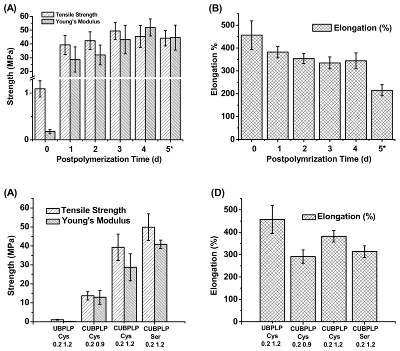
The stress-strain curves were characteristic of elastomers (Figure 1B). After 1d post-polymerization, the tensile strength of CUBPLP-Cys 1.2 increased 8 fold, compared to BPLP-Cys. Elongation was also increased from 160% to 420%. These results not only confirmed the successful incorporation of urethane bonds, but also proved the concept that urethane bond doping can dramatically increase the mechanical strength and elasticity. The effect of post-polymerization conditions on the mechanical properties of CUBPLP-Cys 1.2 was also investigated. From Figure 2A, longer post-polymerization times resulted in increased polymer tensile strength and Young’s modulus with a corresponding decrease in elongation. However, post-polymerization time did not have much impact on the mechanical property of CUBPLP-Cys 1.2 (with tensile strength ranging from 39.31–49.41 MPa). This is because the side hydroxyl and carboxyl groups of POC have been partially reacted with cysteine and isocyanate groups, which lowered the post-polymerization (crosslinking) potential. It was found that mechanical properties could be tuned by varying the monomer feeding ratios (Figure 2C and D). After 1d post-polymerization, the tensile strength raised from 13.71±2.19 MPa (CUBPLP-Cys 0.9) to 39.31±6.97 MPa (CUBPLP-Cys 1.2). Stronger mechanical properties and increased elasticity with increased feeding ratio of diisocyanate is due to the increased amount of urethane bond. Due to the –OH containing R-group of serine, BPLP-Ser provided more active sites for isocyanate reaction. As a result, CUBPLP-Ser 1.2 had a tensile strength of 49.93±7.00 MPa, which is higher than that of CUBPLP-Cys 1.2. However, the increased crosslinking site resulted in loss of elasticity. Compared with CUBPLP-Cys 1.2, the Young’s modulus of CUBPLP-Ser 1.2 was 18.87±2.23 MPa, which is higher than 13.29±1.96 MPa (CUBPLP-Cys 1.2). The elongation was decreased from 381.84±25.34% to 313.22±26.14% as well. Conclusions can be drawn that mechanical properties of UBPLPs can be manipulated by (1) post-polymerization condition (2) feeding ratio of diisocyanate and (3) choice of amino acids. Tensile strengths up to 49.41±6.17 MPa and elongation up to 456.60±62.49% were obtained under the synthesis conditions investigated. This is a dramatic improvement over the previously reported mechanical property of crosslinked BPLP, which had tensile strength of only 6.50±0.80 MPa and elongation up to 240±36% [20]. The elasticity of UBPLP can be tailored to match that of the cardiovascular tissue such as smooth muscle tissue, which exhibits elongation of 300% [23].
Figure 2.
Mechanical properties of UBPLPs and CUBPLPs. Effects of postpolymerization conditions on the UBPLP-Cys 1.2 (A) tensile strength and Young’s modulus, and (B) elongation. Effects of feeding formulation on the (C) tensile strength and Young’s modulus, and (D) elongation. (In A and B, * denotes that samples were further crosslinked under 120°C for the fifth day.)
The fluorescent properties of UBPLPs were also evaluated. The fluorophore of BPLPs has been studied in detail previously, and a 6-membered ring structure was claimed to contribute to the fluorescence [20]. Among all 20 essential alpha amino acids BPLPs is based on, BPLP-Cys and BPLP-Ser had the strongest fluorescence with quantum yields of 62.3% and 26.0%, respectively. Due to the Red-edge Effect (REE) [24], BPLP-Ser exhibited excitation-dependent emission spectra, which are different from BPLP-Cys that had a fixed emission wavelength. The emission spectra of UBPLP-Cys 1.2 and UBPLP-Ser 1.2 solutions were first recorded under different excitation wavelengths. Figure 3A shows that UBPLP-Cys 1.2 inherited excitation-independent emission spectra from its precursor, BPLP-Cys. The same inheritance from BPLP-Ser to UBPLP-Ser has been verified in that UBPLP-Ser also emitted different emission with changing excitation wavelength (Figure 3B). This result provided evidence that the 6-membered fluorescent ring structure remained intact during the synthesis of UBPLPs. Due to the chain extension of BPLPs, the average number of fluorophores per polymer chain was increased, which lead to self-quenching of the fluorescence [25] and caused the loss of fluorescence intensity after urethane bond doping. Compared to 62.3% and 26.0% quantum yield for BPLP-Cys and BPLP-Ser, respectively, the quantum yield of UBPLP-Cys 1.2 was 38.65% and UBPLP-Ser 1.2 was 19.38%.
Figure 3.
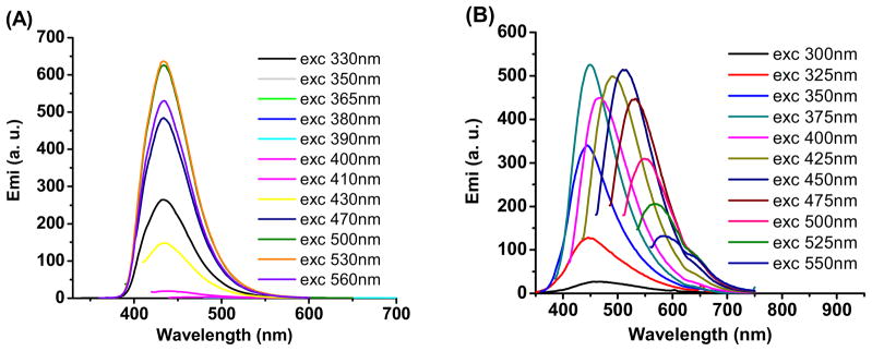
Emission spectra of (A) UBPLP-Cys and (B) UBPLP-Ser under different excitation wavelengths.
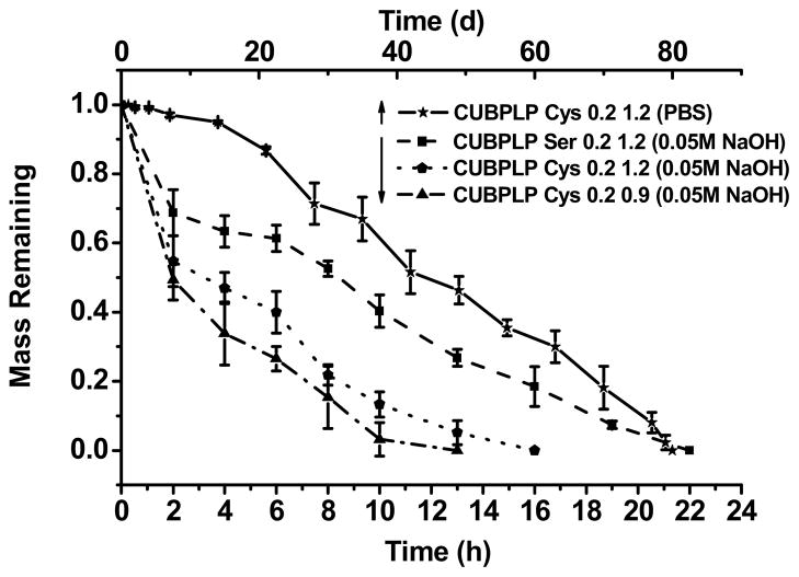
The degradation profiles of CUBPLPs under different conditions are presented in Figure 4. All tested polymers were post-polymerized for 1d. From the accelerated degradation (in NaOH solution), CUBPLP-Cys 0.9 reached complete degradation faster than CUBPLP-Cys 1.2 due to less urethane bond doping. This is because of the higher amount of hydrolytic-resistant urethane bonds present in CUBPLP-Cys 1.2 than in CUBPLP-Cys 0.9. It was also observed that CUBPLP-Ser 1.2 had a longer degradation time. This result further confirmed that the –OH group from serine reacted with isocyanate groups, which led to the formation of more urethane bonds. The complete degradation in PBS was also conducted. CUBPLP-Cys 1.2 degraded completely within 80 days. It can be concluded that the degradation rate of UBPLPs can be adjusted by varying the feeding ratios of diisocyanate to pre-polymers and the choice of amino acids. Therefore, UBPLPs with tunable mechanical property and degradation rate can be tailored to meet the requirements of various soft tissue engineering applications.
Figure 4.
Degradation studies of CUBPLP-Cys and CUBPLP-Ser in PBS (Upper X axis) at 37°C, and 0.01 M NaOH solution at 37°C. All the different CUBPLPs li sted were post-polymerized for 1 day at 80°C.
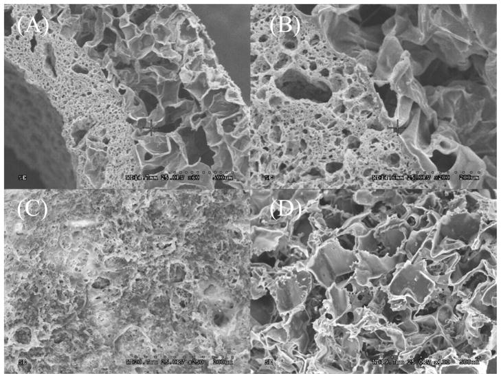
In addition to matching the mechanical properties of native tissue, a successful design for vascular grafts should also be made to replicate the stratified architecture of native blood vessel. Due to the complexity of the microarchitectural of native vascular tissue, facilitating cell growth and extracellular matrix (ECM) compartmentalization is critical to mimic a native-like tissue. To address this issue, a triphasic scaffold composed of a rough inner lumen surface, middle layer of porous scaffold with pore size of 1–20 μm, and outer layer of porous scaffold with pore size of 150–250 μm was fabricated. It was demonstrated that a rough surface is more favorable for endothelial cells [26], and pore size of 1–20 μm is preferable for the compartmentalization of endothelial cells and smooth muscle cells simulating the elastic lamina in native vessels [22]. Pore sizes of 150–250 μm have been proven to be ideal for growth of fibroblast and formation of ECM [27]. SEM images were taken to observe scaffold morphology (Figure 5). From Figure 5A, it can be seen that CUBPLPs can be easily fabricated into tubular architecture. Since layers were unified by post-polymerization, the integration was seamless, which could be clearly observed in Figure 5B. The pore size of middle layer and outer layer could also be confirmed. The roughness of the inner luminal surface and porous surface of outer layer were shown in Figure 5C and 5D, respectively. This design is capable of seeding different cell types. Endothelial cells can be seeded specifically on the inner surface whereas smooth muscle cells and fibroblasts may be seeded directly on outer layer.
Figure 5.
Morphology of UBPLPs triphasic scaffold. (A) cross-section of the scaffold; (B) seamless integration of outer layer and middle layer; (C) rough surfaces of inner lumen; (D) porous outer phase.
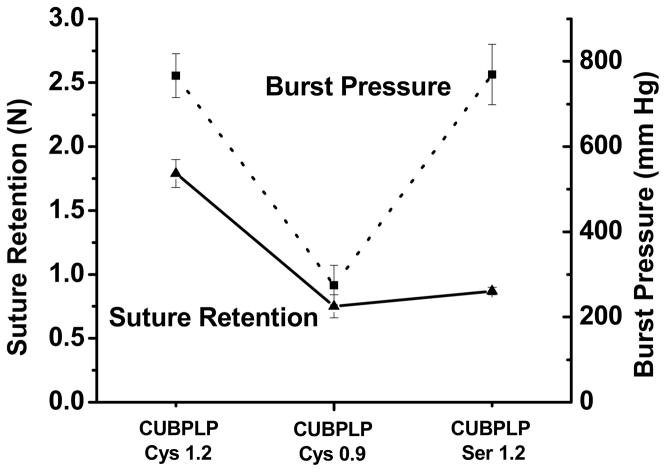
As discussed above, a porous scaffold should be strong and elastic enough for not only surgical handling but also sustaining the structure during in vitro bioreactor training or in vivo physiological conditions [28]. It has also been proven that mechanical compliance plays a major role in determining graft patency [11]. To evaluate the mechanical property of this triphasic scaffolds, burst pressure and suture retention were investigated. Burst pressure is a key parameter of a tissue engineering vascular graft. Suture retention is critical for surgical handling. From Figure 6, the mechanical property of the scaffolds was affected by feeding ratios of diisocyanate. As the middle layer mainly provided the resistance to burst pressure due to less porosity, there was no significant difference between CUBPLP-Cys 1.2 and CUBPLP-Ser 1.2. Both of them exhibited burst pressures around 800 mmHg. In our previous studies, biphasic scaffold with a non-porous inner layer was designed using POC [22] and contributed to most of the mechanical strength. With a layer thickness of 400 μm, POC biphasic scaffolds had burst pressures below 1000 mmHg. However, the solid inner layer may completely block the communications between endothelial cells and smooth muscle cells. With a porous middle layer, the current design of triphasic scaffold may not only allow fluid transportation, but also maintain a burst pressure of 800 mmHg, which is expected to be sufficient to withstand arterial blood pressure [29]. As shown in Figure 6, triphasic scaffold fabricated from CUBPLP-Cys 1.2 had the highest suture retention of 1.79±0.10 N, which met the standard (1.7 N) for surgical suturing [29]. In addition to achieving the desired mechanical properties, the design of triphasic vascular scaffold showed great improvements in replicating native structure of blood vessel than the previous POC biphasic scaffold. Thus, the triphasic CUBPLP vascular scaffold holds great potential for in situ vascular tissue engineering.
Figure 6.
Suture retention strength (left Y axis) and burst pressure (right Y axis) of CUBPLP-Cys 1.2, CUBPLP-Cys 0.9, and CUBPLP-Ser 1.2 triphasic scaffolds.
The biocompatibility of UBPLPs was evaluated for both films and degradation products. From Figure 7A, comparable cell viability was obtained on all CUBPLPs and PLGA films. All films supported cell proliferation during the 7d cell culture period demonstrating good material-cell interactions of CUBPLPs. From SEM images, 3T3 fibroblasts displayed a stretched morphology and formed a cell layer that covered film surface. For biodegradable polymers, the cytotoxicity of degradation products is also important. Since degradation of urethane, amide, and ester bonds are mostly driven by hydrolysis, maximum amount of degradation products were yielded by an accelerated degradation in strong base solution [30]. The MTT results presented in Figure 7B indicated that after 24h incubation, all investigated UBPLPs and CUBPLPs exhibited comparable cytotoxicity to the FDA approved PLGA at all dilutions. Therefore, CUBPLPs and UBPLPs could potentially meet the cytocompatibility requirements for biomedical applications.
Figure 7.
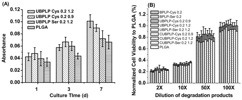
Cytotoxicity studies of CUBPLPs films and degradation products. (A) 3T3 fibroblast cells were cultured on CUBPLPs films at different time points; (B) 3T3 fibroblast cells were cultured with UBPLPs and CUBPLPs degradation products for 24h. PLGA films and degradation products were used as controls.
Up to date, organic or inorganic dyes have been widely incorporated in biodegradable polymers for theranostic applications [31]. However, the toxicity of those dyes, such as CdTe and FITC, still remains a significant concern for biomedical applications in humans. The strong photoluminescent property of UBPLPs may be used to construct an organic dye-free theranostic system. Previously, BPLPs have been fabricated into nanoparticles with a size of 80 nm via nanoprecipitation technique [20]. Due to the sticky nature and acidity, BPLP nanoparticles were only stable in DI water and dissociated in PBS. Thus BPLP nanoparticles were incapable of being used in physiological environment. The main cause was considered as the superfluous hydrophilic groups of polymer backbone. During the reaction between BPLPs and diisocyanate, a large amount of carboxyl and hydroxyl groups have been consumed, which can be confirmed by a more neutral pH of UBPLPs nanoparticles solution (pH 6.3) compared to BPLPs nanoparticles (pH 4.3). Using the nanoprecipitation technique, UBPLP-Ser 1.2 was able to form stable nanoparticles in PBS. The average size of nanoparticle measured by dynamic light scattering (DLS) was 103 nm. This result was confirmed by TEM images of nanoparticles in PBS. From Figure 8A, nanoparticles showed a spherical shape with an average diameter of 103 nm. An even dispersion of nanoparticles was also observed (Figure 8A inset). The cytotoxicity of UBPLPs nanoparticles was evaluated by MTT assay (Figure 8B). Due to the reduced acidity, UBPLPs nanoparticles were found to be more cytocompatible than BPLPs at high concentration (10 mg/mL, 2X dilution). The cell viability of UBPLPs nanoparticles was also found to be significantly higher than quantum dots under all dilutions, and UBPLPs nanoparticles showed a comparable cytotoxicity to PLGA nanoparticles at 2, 10, and 50X dilution. Since nanoparticles injected in the blood circulation will be diluted [32], cytotoxicity at low concentration is critical to nanoparticle solutions. At 100X dilution, the cell viability of UBPLP-Cys 1.2 nanoparticles is significantly higher than that of PLGA nanoparticles. All the results supported the excellent cytocompatibility of UBPLPs nanoparticles.
Figure 8.
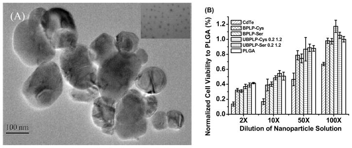
Morphology and cytotoxicity study of UBPLPs nanoparticles. (A) TEM images of UBPLP-Ser 1.2 nanoparticles. Inset is an image captured under higher magnification showing evenly dispersion of nanoparticles; (B) Evaluation of cytotoxicity of BPLPs and UBPLPs nanoparticle solutions at different dilution. PLGA nanoparticles were used as a control.
The capability of UBPLPs nanoparticles as a drug delivery device was evaluated by in vitro encapsulation and release of 5-fluorouracil (5F). Since 5F can be dissolved in both PBS and THF, two formulae of drug encapsulations were conducted. When 5F was dissolved in polymer solution (Formula A), a loading efficiency of 57.6% was obtained. Interestingly, loading efficiency was dramatically increased to 91.84% when 5F was dissolved in PBS (Formula B). This is because of the loose physical bonding between drug and nanoparticle surface in Formula B. This difference also influenced in vitro drug release profile (Figure 9). From Figure 9A, Formula B reached 90% release of 5F within 24h. However, Formula A reached complete release after 120h. Formula B showed a 53% burst release within 2h, while Formula A exhibited a more sustained drug release (Figure 9B). Although high loading efficiency could be obtained in Formula B, the loose bonding between drug and nanoparticle surface led to burst release. The above results supported that UBPLP nanoparticles may potentially serve as drug delivery carriers.
Figure 9.
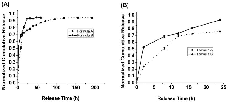
Drug release profiles of 5F-loaded UBPLP-Ser nanoparticles. (A) Complete release profiles; and (B) 24h-release profiles. For drug loading, formula A represents that 5F was dissolved in polymer solutions, while formula B represents that 5F was dissolved in PBS.
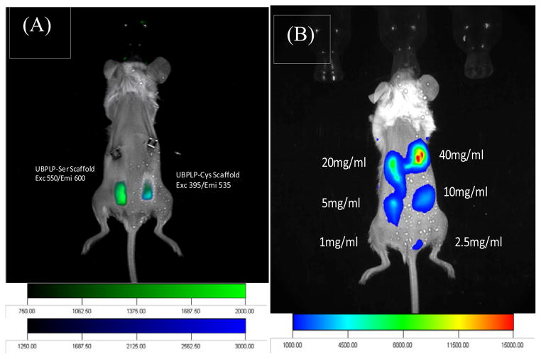
Both CUBPLP-Cys 1.2 and CUBPLP-Ser 1.2 tubular triphasic scaffolds were implanted subcutaneously onto the back of black mice (C57BL/6 J) for in vivo fluorescence imaging studies as similar to others [33, 34]. From Figure 10A, both scaffolds were readily detected by a non-invasive imaging system. Same procedure was conducted to image UBPLP-Ser nanoparticles in vivo (Figure 10B). It was found that a clear fluorescence signal was detected with a concentration of 5 mg/ml. Since the capability of UBPLP-Ser 1.2 nanoparticles as drug delivery device has been demonstrated, the successful in vivo detection supported that UBPLP-Ser 1.2 nanoparticles had great potential for theranostic applications.
Figure 10.
Fluorescence imaging of CUBPLP scaffolds and UBPLP nanoparticles in Black mice (C57BL/6 J). (A) Combined fluorescence images of implanted CUBPLP-Cys and CUBPLP-Ser triphasic scaffold. CUBPLP-cys was imaged under exc 395nm/emi 535nm and CUBPLP-Ser was imaged under exc 550nm/ emi 600nm. (B) In vivo fluorescence images of UBPLP-Ser nanoparticles at various concentrations injected subcutaneously in the back of Black Mice (C57BL/6 J). 100 μl was injected at each point. Exc/emi pair is 550nm/600nm.
Florescent labeling and imaging have fueled the significant growth of life science and medical research due to the increasing demands on analyzing biomolecules, tracking biological process, and visualizing diseases and therapeutic efficacy. In addition to the widely recognized photobleaching and toxicity, it is noteworthy that the traditional fluorescent dyes or quantum dots are just “imaging agents.” They cannot act alone as medical implants to serve as drug delivery vehicles or tissue engineering scaffolds. Combining biomedical implants and imaging agents for drug delivery and tissue engineering has been a significant focus of research in the past few years. Using safe biodegradable implant polymers that intrinsically emit detectable fluorescence in vivo would address the above challenges in drug delivery and tissue engineering, as well as open new windows for other biological and biomedical applications where fluorescence labeling and imaging are needed. We believe that the development of UBPLPs is a timely response to such needs and will impact a broad biological and biomedical applications.
4. Conclusions
We have developed a new class of urethane-doped biodegradable photoluminescent polymers (UBPLPs). UBPLPs demonstrated soft but strong mechanical properties. The triphasic scaffold met the mechanical requirements for the design of off-the-shelf vascular grafts. UBPLPs were also fabricated into stable nanoparticles, and showed a controlled release of anti-cancer drug. UBPLPs showed comparable cytotoxicity to PLGA. The fluorescence of both UBPLPs scaffolds and nanoparticles were clearly detected in vivo. The development of UBPLPs represents a progress in fluorescent biomaterial design and should serve as a new tool in addressing the imminent challenges in drug delivery and tissue engineering where new measurement tools, engineering methods, design principles, non-invasive, and real-time assays are urgently needed to advanced the fields.
Acknowledgments
This work was supported in part by a R01 award EB012575 from the National Institute of Biomedical Imaging and Bioengineering (NIBIB) (to J.Y.), and a National Science Foundation (NSF) CAREER award DMR 1313553 (to J.Y.).
Footnotes
Publisher's Disclaimer: This is a PDF file of an unedited manuscript that has been accepted for publication. As a service to our customers we are providing this early version of the manuscript. The manuscript will undergo copyediting, typesetting, and review of the resulting proof before it is published in its final citable form. Please note that during the production process errors may be discovered which could affect the content, and all legal disclaimers that apply to the journal pertain.
References
- 1.Liu QY, Jiang L, Shi R, Zhang LQ. Synthesis, preparation, in vitro degradation, and application of novel degradable bioelastomers-a review. Prog Polym Sci. 2012;37(5):715–65. [Google Scholar]
- 2.Li YL, Rodrigues J, Tomas H. Injectable and biodegradable hydrogels: gelation, biodegradation and biomedical applications. Chem Soc Rev. 2012;41(6):2193–221. doi: 10.1039/c1cs15203c. [DOI] [PubMed] [Google Scholar]
- 3.Panyam J, Labhasetwar V. Biodegradable nanoparticles for drug and gene delivery to cells and tissue. Adv Drug Deliver Rev. 2003;55(3):329–47. doi: 10.1016/s0169-409x(02)00228-4. [DOI] [PubMed] [Google Scholar]
- 4.Nair LS, Laurencin CT. Biodegradable polymers as biomaterials. Prog Polym Sci. 2007;32(8–9):762–98. [Google Scholar]
- 5.Zhang RY, Ma PX. Poly(alpha-hydroxyl acids) hydroxyapatite porous composites for bone-tissue engineering. I. Preparation and morphology. J Biomed Mater Research. 1999;44(4):446–55. doi: 10.1002/(sici)1097-4636(19990315)44:4<446::aid-jbm11>3.0.co;2-f. [DOI] [PubMed] [Google Scholar]
- 6.Tateishi T, Chen G. Biodegradable polymer scaffold for tissue engineering. Key Eng Mater. 2005;288–289:59–62. [Google Scholar]
- 7.Govender T, Stolnik S, Garnett MC, Illum L, Davis SS. PLGA nanoparticles prepared by nanoprecipitation: drug loading and release studies of a water soluble drug. J Control Release. 1999;57(2):171–85. doi: 10.1016/s0168-3659(98)00116-3. [DOI] [PubMed] [Google Scholar]
- 8.Yang J, Webb AR, Ameer GA. Novel citric acid-based biodegradable elastomers for tissue engineering. Adv Mater. 2004;16(6):511–16. [Google Scholar]
- 9.Wang YD, Ameer GA, Sheppard BJ, Langer R. A tough biodegradable elastomer. Nat Biotechnol. 2002;20(6):602–6. doi: 10.1038/nbt0602-602. [DOI] [PubMed] [Google Scholar]
- 10.Dey J, Xu H, Shen JH, Thevenot P, Gondi SR, Nguyen KT, et al. Development of biodegradable crosslinked urethane-doped polyester elastomers. Biomaterials. 2008;29(35):4637–49. doi: 10.1016/j.biomaterials.2008.08.020. [DOI] [PMC free article] [PubMed] [Google Scholar]
- 11.Dey J, Xu H, Nguyen KT, Yang JA. Crosslinked urethane doped polyester biphasic scaffolds: potential for in vivo vascular tissue engineering. J Biomed Mater Res. 2010;95A(2):361–70. doi: 10.1002/jbm.a.32846. [DOI] [PMC free article] [PubMed] [Google Scholar]
- 12.Dey J, Tran RT, Shen JH, Tang LP, Yang J. Development and long-term in vivo evaluation of a biodegradable urethane-doped polyester elastomer. Macromol Mater Eng. 2011;296(12):1149–57. doi: 10.1002/mame.201100074. [DOI] [PMC free article] [PubMed] [Google Scholar]
- 13.Gong Y, Zhou Q, Gao C, Shen J. In vitro and in vivo degradability and cytocompatibility of poly(l-lactic acid) scaffold fabricated by a gelatin particle leaching method. Acta Biomater. 2007;3(4):531–40. doi: 10.1016/j.actbio.2006.12.008. [DOI] [PubMed] [Google Scholar]
- 14.Artzi N, Oliva N, Puron C, Shitreet S, Artzi S, Ramos AB, et al. In vivo and in vitro tracking of erosion in biodegradable materials using non-invasive fluorescence imaging (vol 10, pg 704, 2011) Nat Mater. 2011;10(11):896. doi: 10.1038/nmat3095. [DOI] [PMC free article] [PubMed] [Google Scholar]
- 15.Petros RA, DeSimone JM. Strategies in the design of nanoparticles for therapeutic applications. Nat Rev Drug Discov. 2010;9(8):615–27. doi: 10.1038/nrd2591. [DOI] [PubMed] [Google Scholar]
- 16.Yakimansky AV, Menshikova AY, Shevchenko NN, Shabsels BM, Bazhenova AG, Sel'kin AV, et al. From polymeric nanoparticles to dye-containing photonic crystals: synthesis, self-assembling, optical features, and possible applications. Polym Advan Technol. 2009;20(6):581–8. [Google Scholar]
- 17.Jaiswal JK, Mattoussi H, Mauro JM, Simon SM. Long-term multiple color imaging of live cells using quantum dot bioconjugates. Nat Biotechnol. 2003;21(1):47–51. doi: 10.1038/nbt767. [DOI] [PubMed] [Google Scholar]
- 18.Jamieson T, Bakhshi R, Petrova D, Pocock R, Imani M, Seifalian AM. Biological applications of quantum dots. Biomaterials. 2007;28(31):4717–32. doi: 10.1016/j.biomaterials.2007.07.014. [DOI] [PubMed] [Google Scholar]
- 19.Yanushevich YG, Staroverov DB, Savitsky AP, Fradkov AF, Gurskaya NG, Bulina ME, et al. A strategy for the generation of non-aggregating mutants of Anthozoa fluorescent proteins. FEBS Lett. 2002;511(1–3):11–4. doi: 10.1016/s0014-5793(01)03263-x. [DOI] [PubMed] [Google Scholar]
- 20.Yang J, Zhang Y, Gautam S, Liu L, Dey J, Chen W, et al. Development of aliphatic biodegradable photoluminescent polymers. P Natl Acad Sci USA. 2009;106(25):10086–91. doi: 10.1073/pnas.0900004106. [DOI] [PMC free article] [PubMed] [Google Scholar]
- 21.Williams ATR, Winfield SA, Miller JN. Relative fluorescence quantum yields using a computer-controlled luminescence spectrometer. Analyst. 1983;108(1290):1067–71. [Google Scholar]
- 22.Yang J, Motlagh D, Webb AR, Ameer GA. Novel biphasic elastomeric scaffold for small-diameter blood vessel tissue engineering. Tissue Eng. 2005;11(11–12):1876–86. doi: 10.1089/ten.2005.11.1876. [DOI] [PubMed] [Google Scholar]
- 23.Webb AR, Yang J, Ameer GA. Biodegradable polyester elastomers in tissue engineering. Expert Opin Biol Ther. 2004;4(6):801–12. doi: 10.1517/14712598.4.6.801. [DOI] [PubMed] [Google Scholar]
- 24.Demchenko AP. The red-edge effects: 30 years of exploration. Luminescence. 2002;17(1):19–42. doi: 10.1002/bio.671. [DOI] [PubMed] [Google Scholar]
- 25.Phillips RL, Kim IB, Tolbert LM, Bunz UH. Fluorescence self-quenching of a mannosylated poly(p-phenyleneethynylene) induced by concanavalin A. J Am Chem Soc. 2008;130(22):6952–4. doi: 10.1021/ja802094s. [DOI] [PubMed] [Google Scholar]
- 26.Chung TW, Liu DZ, Wang SY, Wang SS. Enhancement of the growth of human endothelial cells by surface roughness at nanometer scale. Biomaterials. 2003;24(25):4655–61. doi: 10.1016/s0142-9612(03)00361-2. [DOI] [PubMed] [Google Scholar]
- 27.Li WJ, Laurencin CT, Caterson EJ, Tuan RS, Ko FK. Electrospun nanofibrous structure: a novel scaffold for tissue engineering. J Biomed Mater Res. 2002;60(4):613–21. doi: 10.1002/jbm.10167. [DOI] [PubMed] [Google Scholar]
- 28.Sodian R, Lemke T, Fritsche C, Hoerstrup SP, Fu P, Potapov EV, et al. Tissue-engineering bioreactors: A new combined cell-seeding and perfusion system for vascular tissue engineering. Tissue Eng. 2002;8(5):863–70. doi: 10.1089/10763270260424222. [DOI] [PubMed] [Google Scholar]
- 29.Huynh T, Abraham G, Murray J, Brockbank K, Hagen PO, Sullivan S. Remodeling of an acellular collagen graft into a physiologically responsive neovessel. Nat Biotechnol. 1999;17(11):1083–6. doi: 10.1038/15062. [DOI] [PubMed] [Google Scholar]
- 30.Marques AP, Reis RL, Hunt JA. The biocompatibility of novel starch-based polymers and composites: in vitro studies. Biomaterials. 2002;23(6):1471–8. doi: 10.1016/s0142-9612(01)00272-1. [DOI] [PubMed] [Google Scholar]
- 31.Zhang Y, Yang J. Design strategies for fluorescent biodegradable polymeric biomaterials. J Mater Chem B. 2013;1(2):132–48. doi: 10.1039/C2TB00071G. [DOI] [PMC free article] [PubMed] [Google Scholar]
- 32.Kataoka K, Harada A, Nagasaki Y. Block copolymer micelles for drug delivery: design, characterization and biological significance. Adv Drug Delivery Rev. 2001;47(1):113–31. doi: 10.1016/s0169-409x(00)00124-1. [DOI] [PubMed] [Google Scholar]
- 33.Terai T, Nagano T. Fluorescent probes for bioimaging applications. Curr Opin Chem Biol. 2008;12(5):515–21. doi: 10.1016/j.cbpa.2008.08.007. [DOI] [PubMed] [Google Scholar]
- 34.Abraham T, Wadsworth S, Carthy JM, Pechkovsky DV, McManus B. Minimally invasive imaging method based on second harmonic generation and multiphoton excitation fluorescence in translational respiratory research. Respirology. 2011;16(1):22–33. doi: 10.1111/j.1440-1843.2010.01898.x. [DOI] [PubMed] [Google Scholar]


