Abstract
We introduce a novel type of droplet generator that produces droplets of a volume set by the geometry of the droplet generator and not by the flow rates of the liquids. The generator consists of a classic T-junction with a bypass channel. This bypass directs the continuous fluid around the forming droplets, so that they can fill the space between the inlet of the dispersed phase and the exit of the bypass without breaking. Once filled, the dispersed phase blocks the exit of the bypass and is squeezed by the continuous fluid and broken off from the junction. We demonstrate the fixed-volume droplet generator for (i) the formation of monodisperse droplets from a source of varying flow rates, (ii) the formation of monodisperse droplets containing a gradation of solute concentration, and (iii) the parallel production of monodisperse droplets.
INTRODUCTION
Microfluidic devices produce monodisperse droplets with a high-level of control over size and contents, making them useful for applications in biotechnology, material synthesis, optofluidics, and medical diagnostics.1 Architectures most commonly used to form droplets are hydrodynamic flow focusing devices,2 capillary devices,3 and T-junctions.4, 5 Other methods include droplet formation in microchannel arrays and at terrace-like structures.6 The volume of the droplets created in all these devices depends on the geometry of the droplet maker, on the fluid properties, on the flow rates, or on combinations of these parameters.7 For example, the volume of droplets produced at T-junctions under squeezing conditions4 linearly depends on the ratio of flow rates of the dispersed and the continuous phase.4, 8
On the one hand, the dependency of the volume of droplets on flow rates, device geometry or fluid properties is convenient, because it provides a means to tune droplets to their desired size.9 On the other hand, it requires accurate control of flows that are stable in time, as fluctuations in flow rates invariably lead to corresponding fluctuations in the size of the droplets.10 Hence, chips need to be externally connected to precise pumps such that these lab-on-a-chips are sometimes ironically referred to as chips-in-a-lab. This limits the use of droplet-based assays in resource poor settings, where flows cannot be controlled with great precision.
In this paper, we introduce a new type of droplet generator in which the volume of droplets depends primarily on the geometry of the droplet generator and not on flow rates nor on fluid properties. The advantage of the fixed-volume droplet generator is that it ensures generation of droplets of a single size, even in environments in which fluids cannot be delivered at constant rates, or in which the rates are difficult to tune to the requisite values. After characterizing the fixed-volume droplet generator, we demonstrate how it facilitates the development of simple and robust droplet-based laboratories-on-a-chip. Without external pumps and using gravity as the sole driving force, we show the continuous production of monodisperse droplets of a fixed volume, each containing a different but known solute concentration. Another application that benefits from the decoupling between the volume of the droplets and the flow rates is the parallelization of droplet production, as we demonstrate in this paper.
RESULTS
Fixed-volume droplet generator
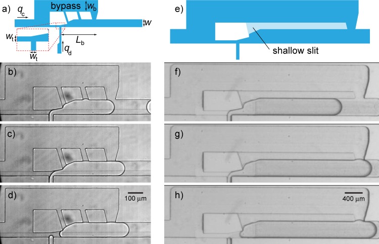
Our droplet generator consists of a T-junction with a bypass channel around it. Such bypasses have previously been used in microfluidics to produce alternating streams of droplets, synchronize droplet streams, merge droplets, and perform more complex operations.12 Figure 1 illustrates the formation of a droplet in the fixed-volume droplet generator. A formation cycle starts with the dispersed phase flowing from the side channel into the main channel and blocking it. In contrast to a classic T-junction, the forming droplet grows without being squeezed by the continuous phase, because the continuous phase flows around the droplet through the bypass (Fig. 1b). Once the dispersed phase fills the channel between the inlet of the dispersed phase and the exit of the bypass, it blocks this exit (Fig. 1c); consequently, the continuous phase squeezes the dispersed phase until it breaks and a droplet is released (Fig. 1d). This block-and-break mechanism thus enables the formation of droplets with a volume set by the volume between the inlet of the dispersed phase and the exit of the bypass. The droplet volume hence predominantly depends on the geometry of the device and not on the flow rates.
Figure 1.
(a) Design of a fixed-volume droplet generator. (b)-(d) Micrographs showing a formation cycle. (b) The dispersed phase injected at a rate, qd, flows into the main channel and blocks it, such that the continuous phase, introduced at a rate, qc, flows around the forming droplet through the bypass. The back of the forming droplet stays at the same location in the T-junction until the front blocks the exit of the bypass (c) resulting in the rapid collapse of the back and the release of a droplet (d). See also the movie in the supplementary material.11 (e)-(h) Multilayer design of the fixed-volume droplet generator: the bypass is connected to the main channel (depth: h) through a shallow slit (depth: ).
The role of the connecting channels between the bypass and the main channel is to ensure that the continuous phase is able to flow around forming droplets. Except for short bypasses, the exit of the bypass is still blocked by the preceding droplet when a new droplet starts to grow. Without the connecting channels, this droplet breaks prematurely (see supplementary material11). The connecting channels are hence essential. Besides the planar design shown in Figs. 1a, 1b, 1c, 1d, we also introduce a multilayer design in which the bypass is connected to the main channel through a shallow slit (Figs. 1e, 1f, 1g, 1h). Guidelines for the optimal design of the droplet generator based on the physics of droplet formation are provided in the supplementary material together with the AutoCAD drawings for the planar devices.11
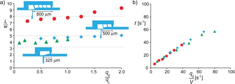
To show that the size of the droplets is determined by the geometry of the droplet generator, we created water droplets in oil and measured their size in three different devices. The devices were fabricated in PDMS13 with different distances, Lb, between the inlet of the dispersed phase and the exit of the bypass channel. The length of the droplets, L, as measured from our micrographs, agrees with this distance, as shown in Fig. 2a. The slight dependence of the size of the droplets on the ratio of the flow rates arises from the fact that the duration of the final part of the formation cycle (Figs. 1c, 1d) depends on the flow rate of the continuous phase; this can be mitigated by minimizing the local volume at the inlet of the dispersed phase.
Figure 2.
(a) Length of droplets as a function of the ratio of flow rates of the dispersed and the continuous phase. The length, which is normalized by the width of the main channel, corresponds well to the distance between the T-junction and the exitof the bypass channel (Lb) as indicated by the dashed lines. (b) The formation frequency of the data corresponding to (a) is proportional to the ratio of the flow rate of the dispersed phase and the droplet volume (). The standard deviation of the length (a) and frequency (b) data are both below 1% for all data points. Geometries and conditions: () = (100, 25, 150, 42) μm and for and , and () = (100, 25, 150, 24) μm and for .
To further demonstrate that the volume of the droplets primarily depends on geometry, we produced aqueous droplets of different viscosities (1 mPas–53 mPas) in two different types of carrier oils. As expected based on the physics of drop formation in classic T-junctions,4 these experiments show that the size of droplets produced with our fixed-volume droplet generator is indeed independent of the fluid properties as long as the capillary number is below (see Fig. S4 in the supplementary material11). The fixed-volume droplet generator can hence be used for aliquoting different types of samples—a feature of particular importance to, for example, point-of-care diagnostic applications.
Because the droplet size is nearly constant, the frequency, f, at which droplets form can be tuned by adjusting the flow rate of the dispersed phase. The time, , needed to form a droplet equals the volume of the droplet () divided by the rate at which the dispersed phase is injected. Hence, . This simple prediction agrees well with the frequency observed in experiments as shown in Fig. 2b.
Independence of drop size with respect to fluctuations in flow
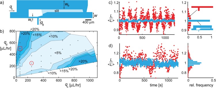
The concept of the fixed-volume droplet generator can be used to produce droplets over a large range of volumes, because the operating principle does not depend on the absolute size of the channels, provided the capillary number is small. We verified this hypothesis by using scaled versions of the fixed-volume droplet generator, with main channels that were 4× smaller (25 μm) and 4× larger (400 μm) than the 100 μm wide channel shown in Fig. 2a. Droplets as small as 50 pl were produced in the 25 μm wide channels, while the 400 μm wide channels allowed the production of droplets well over 300 000 pl (0.3 μl) in volume. While the devices containing the 25 μm and 100 μm wide channels were made out of PDMS as described before, the 400 μm wide channels were made in polycarbonate (PC) with the bypass channel in the form of a slit that is less deep () than the surrounding channels (Fig. 3a).
Figure 3.
(a) Multilayer variant of a fixed-volume droplet generator in which the bypass channel is connected to the main channel through a shallow slit. (b) Map of the flow rates of the continuous and dispersed phase showing the deviation of the measured length of the droplets from the reference length . (c) Time-series of the relative drop size and corresponding histogram for a fixed-volume droplet generator (blue dots) and a classic T-junction (red dots). The conditions are indicated by the circle in (b). The average droplet length in the fixed-volume droplet generator and classic T-junction were and respectively. (d) Same as in (c) with conditions indicated by the square in (b). The average length is for both cases. Geometries: fixed-volume droplet generator () = (400, 100, 600, 200,100) μm, classic T-junction (w, h) = (400, 200) μm.
Further characterization of the performance of the fixed-volume droplet generator was performed in these PC devices. To study the sensitivity of the volume of the droplets to the flow rates, we systematically varied these rates and compared the measured length of the droplets with a reference length. Deviations from this length are smallest for comparable flow rates of the dispersed and the continuous phase () and systematically increase when departing from this ratio, as shown in the map in Fig. 3b. The main conclusion from this map is that deviations of less than 5% were found for a wide range of combinations of flow rates. Hence, within this window of operation, the droplet generator ensures a nearly constant drop size irrespective of the flow rates.
The fixed-volume droplet generator can hence be used to minimize the influence of temporal fluctuations in the flow rates on the uniformity in droplet size. To illustrate this, we compare the droplet size distribution obtained in a fixed-volume droplet generator with the size distribution obtained in a classic T-junction, which consists of branches of equal width, w (see inset Fig. 3c). These experiments were done simultaneously by injecting the continuous phase into the two devices using a single syringe pump loaded with two syringes. The dispersed phase was injected into the devices in a similar fashion using a second syringe pump. This ensures that the fluctuations in flow rates arising from the periodic mechanism of the syringe pumps10 are the same for both devices. As expected, the size of the droplets is much more uniform in the fixed-volume droplet generator as compared to the classic T-junction device (Figs. 3c, 3d).
Gravity driven systems
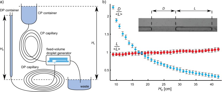
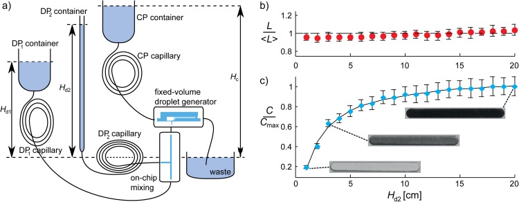
The ability to produce monodisperse droplets even if the flow rates change in time allows the construction of simple and robust systems for generating droplets of precisely defined volumes in point-of-care or in-field settings. Simple sources to drive fluids through channels include centrifugation, gravitation, or suction (syringe vacuum14). Here, we demonstrate gravity driven systems for the production of water-in-oil droplets in a fixed-volume droplet generator. Oil (2% (w/w) solution of Span-80 in hexadecane) and distilled water are supplied from two separate reservoirs such that their flow rates are proportional to the height difference between the free surfaces in the reservoirs and in the waste container. We used a wide reservoir for the oil, such that the height difference, Hc, does not change appreciably during draining (Fig. 4a). By contrast, water was supplied from a tall and narrow (ID = 0.79 mm) reservoir such that the height difference, Hd, changes from 42 cm to 9 cm over the course of the experiment. We measured both the length of the droplets, L, and the distance between them, D. While the large variation in D reflects the -fold variation of the ratio of flow rates, the length of the droplets is constant within 8% of the average value (Fig. 4b).
Figure 4.
(a) Gravity-driven system for the generation of monodisperse droplets. The continuous phase (CP) is supplied from a wide container such that the rate is constant over the course of the experiment. By contrast, the dispersed phase (DP) is supplied from a tall and narrow container such that the flow rate significantly decreases with time. (b) While the distance between droplets significantly increases over the course of the experiment (blue diamonds), the length of the droplets (red circles) is nearly independent of the pressure head, Hd. The error bars indicate the standard deviation obtained by measuring the length and distance of at least 10 droplets.
An extension of the setup described above enables the production of monodisperse droplets comprising a gradation of solute concentration. This is accomplished by merging a solvent stream with a miscible stream carrying the solute, before this mixture is emulsified using a fixed-volume droplet generator (Fig. 5a). The streams were merged in a T-junction on a separate chip such that the concentration of solute in the mixture, C, depends on the flow rates of the streams. The flow rate of the solvent stream is nearly constant during the experiment, because it is supplied from a wide container. By contrast, the stream carrying the solute is delivered from a tall and narrow reservoir, resulting in a continuously decreasing flow rate. Consequently, the concentration of solute in the mixture decreases in time, with successive droplets. This concentration, C, depends on the undiluted concentration, , and the flow rate of solvent, , and solute, . These rates, in turn, depend on the pressure heads () of the two liquids and on the hydrodynamic resistances of the capillaries: , with and the resistances of capillaries for solvent and solute, respectively. The pressure difference between the T-junction and the waste, PT, depends on the total flow rate according to , where RT is the resistance of the device behind the T-junction. These equations combine to the following expression for the concentration of solute: . The pressure heads of the two liquids can be estimated as: , where are densities of the liquids and g is the gravitational acceleration. The cross-sectional area of the solvent reservoir is large in comparison to that of the solute, such that is nearly constant. Hence, all terms except in the expression for C are constants and the expression simplifies to , where A, B, D, and E are constants. We performed an experiment with water as the solvent, a 5% (w/w) aqueous solution of ink (solute), and a 2% (w/w) solution of Span-80 in hexadecane as the continuous phase. We measured the length of the droplets and the median brightness in the center of the droplets. The concentration ratio was calculated from the intensities using the Lambert Beer equation. Whereas the length of the droplets is nearly constant over the course of the experiment (Fig. 5b), the ink concentration decreases as shown in Fig. 5c. The excellent match between the measured concentrations and the fit (solid line) forms the basis for designing simple chips that do not require power for generating flow, and are capable of executing intricate assays in the field.
Figure 5.
(a) Setup for the facile generation of monodisperse droplets containing a solute (ink), whose concentration gradually decreases with time, that is, for successive droplets. Prior to emulsification, a concentrated stream of ink () supplied from a tall and narrow container (DP2) is diluted by mixing it on a separate chip with a stream of solvent supplied from a wide container (DP1). The concentration of this mixture, C, continuously decreases due to a decreasing flow rate of the solute stream caused by a decrease in the pressure head . (b), (c) While the length of the droplets is nearly constant (b), the concentration of ink in the droplets (c) depends on according to , with A, B, D, and E constants, as shown from the excellent agreement between the experimental data and the fit (solid line). The error bars indicate the standard deviation obtained by measuring the length and concentration of at least 10 droplets.
Parallelization
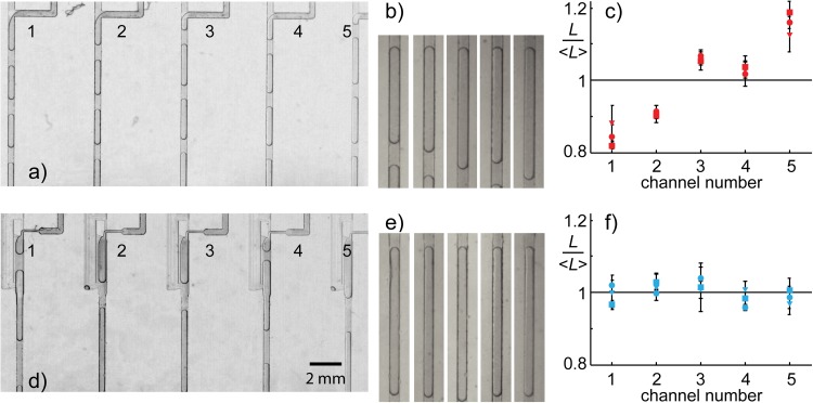
The fixed-volume droplet generator also provides an advantage for the parallelization of droplet generation. A challenge in parallelization is the equal distribution of fluids to the individual junctions where the droplets are produced.15 Small differences in hydrodynamic resistance of the channels that connect the inlet of the phases to the different junctions lead to differences in the flow rates. For an array of classic T-junctions, minimizing these flow differences is essential, because non-uniformities in flow lead to the production of droplets of different sizes at the different junctions. This puts strict requirements on the fabrication tolerances. Since the volume of droplets produced at a fixed-volume droplet generator is decoupled from the flow rates, a precise flow distributor is not needed, which simplifies device fabrication. We show this by comparing the size of droplets produced in an array of classic T-junction (Fig. 6a) and in an array of fixed-volume droplet generators (Fig. 6d). To demonstrate that the array of fixed-volume droplet generators does not require a precise flow distributor, we intentionally supplied fluids at different rates to the junctions by designing the chip such that the length of the channels between the shared inlets of the two phases and the junctions is not the same. Based on this design, the flow rate of the continuous phase is largest at the first junction and is systematically smaller in junctions two to five. The opposite is true for the flow rate of the dispersed phase. This unequal flow distribution leads to the generation of the smallest droplets at the first classic T-junction and the largest droplets at the fifth, as shown in Figs. 6b, 6c. By contrast, no systematic variations were observed in the array of fixed-volume droplet generators (Figs. 6e, 6f). This demonstration shows that the fixed-volume droplet generator may be used to alleviate, or minimize, the flow distribution problem in the parallel generation of droplets, simply because the flow distributor can be omitted. Such parallel systems may be used for high-throughput formulation of monodisperse emulsions or in analytical applications.16
Figure 6.
Comparison between droplets produced in parallel at T-junctions (a)–(c) and fixed-volume droplet generators (d)–(f). Unequal flow distribution to the five junctions results in unequal sized droplets when using T-junctions, whereas the size is nearly the same when using fixed-volume droplet generators. The error bars indicate the standard deviation obtained by measuring the length of at least 10 droplets. Conditions: and (circles and micrographs), (squares), (triangles). In the case of , frequencies of generation of droplets in succeeding channels were: f = (0.46, 0.45, 0.45, 0.46, 0.46) s−1 for T-junctions, f = (0.35, 0.35, 0.37, 0.36, 0.36) s−1 for fixed-volume droplet generators; volume fractions estimated as = (0.82, 0.81, 0.85, 0.85, 0.86) for T-junctions, ϕ = (0.83, 0.86, 0.85, 0.84, 0.85) for fixed-volume droplet generators. A detailed design of the devices is provided in the supplementary material.11
SUMMARY
We have introduced and characterized a novel type of droplet generator for the production of microdroplets that have a volume depending primarily on the geometry of the droplet generator. We have shown that decoupling droplet volume from flow rates ensures the formation of monodisperse droplets even when the rates fluctuate in time.
We have provided three examples that demonstrate the utility of this fixed-volume droplet generator: (i) to minimize the influence of flow rate fluctuations on the volume of droplets produced, (ii) to form more monodisperse drops in parallel systems, and (iii) to design gravity-powered systems that produce monodisperse droplets of either constant or predetermined variation of solute concentration.
The fixed-volume droplet generator makes it possible to vary the volume, velocity and generation frequency of droplets independently. With the volume fixed by the geometry of the droplet generator, the velocity and frequency can be tuned with the flow rates of the continuous and dispersed phase. This should be useful for systematic studies of the hydrodynamics of droplet-based microfluidics as well as for the optimization of biochemical reactions in lab-on-a-chip microfluidic devices.
ACKNOWLEDGMENTS
The authors gratefully acknowledge the Foundation for Polish Science Team Programme 2008/1/1 co-financed by the EU European Regional Development Fund. The work at Harvard was supported by the NSF (DMR-1006546) and the Harvard MRSEC (DMR-0820484).
References
- Theberge A. B., Courtois F., Schaerli Y., Fischlechner M., Abell C., Hollfelder F., and Huck W. T. S., Angew. Chem., Int. Ed. 49, 5846 (2010); 10.1002/anie.200906653 [DOI] [PubMed] [Google Scholar]; Huebner A., Sharma S., Srisa-Art M., Hollfelder F., Edel J. B., and Demello A. J., Lab Chip 8, 1244 (2008); 10.1039/b806405a [DOI] [PubMed] [Google Scholar]; Seemann R., Brinkmann M., Pfohl T., and Herminghaus S., Rep. Prog. Phys. 75, 016601 (2012); 10.1088/0034-4885/75/1/016601 [DOI] [PubMed] [Google Scholar]; Teh S.-Y., Lin R., Hung L.-H., and Lee A. P., Lab Chip 8, 198 (2008). 10.1039/b715524g [DOI] [PubMed] [Google Scholar]
- Anna S. L., Bontoux N., and Stone H. A., Appl. Phys. Lett. 82, 364 (2003); 10.1063/1.1537519 [DOI] [Google Scholar]; Gañán Calvo A. M. and Gordillo J. M., Phys. Rev. Lett. 87, 274501 (2001). 10.1103/PhysRevLett.87.274501 [DOI] [PubMed] [Google Scholar]
- Umbanhowar P. B., Prasad V., and Weitz D. A., Langmuir 16, 347 (2000). 10.1021/la990101e [DOI] [Google Scholar]
- Garstecki P., Fuerstman M. J., Stone H. A., and Whitesides G. M., Lab Chip 6, 437 (2006). 10.1039/b510841a [DOI] [PubMed] [Google Scholar]
- Nisisako T., Torii T., and Higuchi T., Lab Chip 2, 24 (2002); 10.1039/b108740c [DOI] [PubMed] [Google Scholar]; Thorsen T., Roberts W. R., Arnold F. H., and Quake S. R., Phys. Rev. Lett. 86, 4163 (2001). 10.1103/PhysRevLett.86.4163 [DOI] [PubMed] [Google Scholar]
- van Dijke K., Veldhuis G., Schroen K., and Boom R., Lab Chip 9, 2824 (2009); 10.1039/b906098g [DOI] [PubMed] [Google Scholar]; Sugiura S., Nakajima M., Iwamoto S., and Seki M., Langmuir 17, 5562 (2001). 10.1021/la010342y [DOI] [Google Scholar]
- Christopher G. F. and Anna S. L., J. Phys. D: Appl. Phys. 40, R319 (2007). 10.1088/0022-3727/40/19/R01 [DOI] [Google Scholar]
- van Steijn V., Kleijn C. R., and Kreutzer M. T., Lab Chip 10, 2513 (2010). 10.1039/c002625e [DOI] [PubMed] [Google Scholar]
- Nguyen N.-T., Ting T.-H., Yap Y.-F., Wong T. N., Chai J. C.-K., Ong W.-L., Zhou J., Tan S.-H., and Yobas L., Appl. Phys. Lett. 91, 084102 (2007); 10.1063/1.2773948 [DOI] [Google Scholar]; Stan C. A., Tang S. K. Y., and Whitesides G. M., Anal. Chem. 81, 2399 (2009). 10.1021/ac8026542 [DOI] [PubMed] [Google Scholar]
- Korczyk P. M., Cybulski O., Makulska S., and Garstecki P., Lab Chip 11, 173 (2011). 10.1039/c0lc00088d [DOI] [PubMed] [Google Scholar]
- See supplementary material at http://dx.doi.org/10.1063/1.4801637 for (i) a movie of the fixed-volume droplet generator, (ii) guidelines on the optimal design of the droplet generator and measurements of the size of the droplets for different viscosities, and (iii) AutoCAD drawing for the planar fixed-volume droplet generators.
- Cristobal G., Benoit J. P., and Joanicot M., Appl. Phys. Lett. 89, 034104 (2006); 10.1063/1.2221929 [DOI] [Google Scholar]; Frenz L., Blouwolff J., Griffiths A. D., and Baret J. C., Langmuir 24, 12073 (2008); 10.1021/la801954w [DOI] [PubMed] [Google Scholar]; Niu X., Gulati S., Edel J. B., and deMello A. J., Lab Chip 8, 1837 (2008); 10.1039/b813325e [DOI] [PubMed] [Google Scholar]; Zagnoni M. and Cooper J. M., Lab Chip, 10, 3069 (2010). 10.1039/c0lc00219d [DOI] [PubMed] [Google Scholar]
- Duffy D. C., McDonald J. C., Schueller O. J. A., and Whitesides G. M., Anal. Chem. 70, 4974 (1998). 10.1021/ac980656z [DOI] [PubMed] [Google Scholar]
- Abate A. R. and Weitz D. A., Biomicrofluidics 5, 014107 (2011). 10.1063/1.3567093 [DOI] [PMC free article] [PubMed] [Google Scholar]
- de Mas N., Günther A., Kraus T., Schmidt M. A., and Jensen K. F., Ind. Eng. Chem. Res. 44, 8997 (2005); 10.1021/ie050472s [DOI] [Google Scholar]; Li W., Greener J., Voicu D., and Kumacheva E., Lab Chip 9, 2715 (2009). 10.1039/B906626H [DOI] [PubMed] [Google Scholar]
- Damean N., Olguin L. F., Hollfelder F., Abell C., and Huck W. T. S., Lab Chip 9, 1707 (2009); 10.1039/b821021g [DOI] [PubMed] [Google Scholar]; Yamada M. and Seki M., Anal. Chem. 76, 895 (2004). 10.1021/ac0350007 [DOI] [PubMed] [Google Scholar]


