Abstract
This article concerns the design of lower limb prosthesis, both below and above knee. It describes a new computer-based design framework and a digital model of the patient around which the prosthesis is designed and tested in a completely virtual environment. The virtual model of the patient is the backbone of the whole system, and it is based on a biomechanical general-purpose model customized with the patient's characteristics (e.g. anthropometric measures). The software platform adopts computer-aided and knowledge-guided approaches with the goal of replacing the current development process, mainly hand made, with a virtual one. It provides the prosthetics with a set of tools to design, configure and test the prosthesis and comprehends two main environments: the prosthesis modelling laboratory and the virtual testing laboratory. The first permits the three-dimensional model of the prosthesis to be configured and generated, while the second allows the prosthetics to virtually set up the artificial leg and simulate the patient's postures and movements, validating its functionality and configuration. General architecture and modelling/simulation tools for the platform are described as well as main aspects and results of the experimentation.
Keywords: digital patient, lower limb prosthesis, virtual prototyping, human modelling
1. Introduction
During the last decades, several information and communication technology tools, such as computer-aided design (CAD) and computer-aided engineering systems, have been developed to support the product development process in order to reduce the need for physical prototypes, and reduce costs and times. However, in some domains, the level of diffusion is still limited, especially when the product requires a high level of customization and represents the interface with the human body or parts of it. An example is artificial prostheses that have to be designed according to the shape of the specific anatomical area.
In this paper, we focus attention on modular lower limb prostheses, both below knee (transtibial, TT) and above knee (transfemoral, TF), realized by assembling state-of-the-art components in order to obtain maximum comfort and usability [1–3]. Most of components are standards (e.g. foot and knee) and can be selected from a manufacturer's catalogue, while the socket has to be realized on the basis of the patient's anatomy. The socket is the main critical component and it is designed and manufactured almost completely in a manual way, greatly relying on the experience and skills of prosthetics technicians. In addition, the patient plays a key role within the development process because both the standard and custom-fit components are selected and designed accordingly to his/her health conditions and anatomical morphology.
Some CAD/CAM prosthetic systems (e.g. Bioshape and Canfit) are available on the market (http://www.biosculptor.com; http://www.prolutions.net/en; http://www.rodin4d.com; http://www.vorum.com). Through reverse engineering techniques (usually laser scanning), the external shape of the stump from which the socket and the positive chalk are derived can be acquired, and also basic models stored in libraries can be modified. However, they are not integrated with simulation tools, such as finite element analysis (FEA) or multi-body systems, to validate the prosthesis design. In the literature, we can find various works proposing the use of FEA to simulate the behaviour of prosthetic components [4–8] and for analysing socket–residual limb interaction. Some research experiences have also demonstrated the feasibility of a totally computer-based process for socket design based on the integration of CAD and FEA tools [9], but they are not able to manage all phases of the prosthesis development process in an unique environment and do not provide any kind of assistance to the prosthetic technician.
This paper presents the prototype of a new design platform for lower limb prosthesis based on the patient's virtual model and a computer-aided and knowledge-guided approach. The main aim has been to develop a digital model of the amputee to be used by the prosthetic to design and test the prosthesis in a fully virtual environment. To reach the goal of replacing the current process (mainly hand made) with a virtual one, several issues have been considered and addressed: capture and formalization of orthopaedic technicians' knowledge of the process, the acquisition of patient information and morphology by means of diagnostic instruments, the development of integrated solutions to design and test standard and custom-fit components and the use of digital human techniques to simulate the way the prosthesis will behave during walking. The adoption of a digital model to represent the patient is in line with the current research trend focused on multi-scale human modelling as a tool for a wide variety of applications, from ergonomics to work safety and health [10–12].
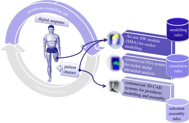
The platform provides the prosthetic technician with a set of interactive tools to design, configure and test the prosthesis. It comprehends two main environments (figure 1): (i) the prosthesis modelling laboratory (PML) and (ii) the virtual testing laboratory (VTL).
Figure 1.
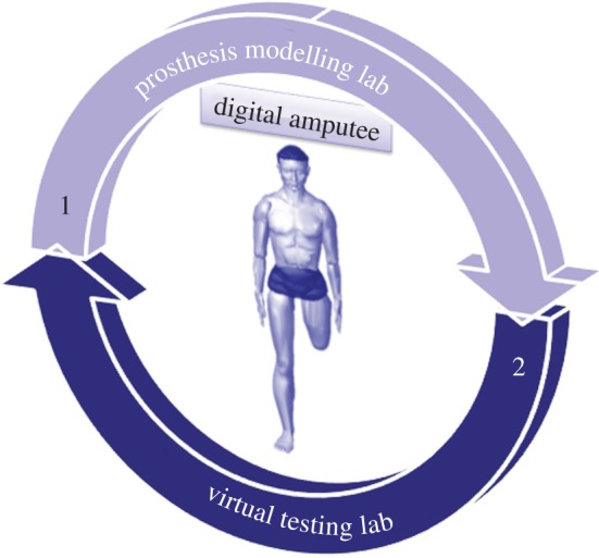
Platform architecture. (Online version in colour.)
The first permits to configure and generate the three-dimensional model of the prosthesis, whereas the second allows the prosthetics to virtually set up the artificial leg and to simulate the patient's postures and movements, validating prosthesis functionality and configuration.
In the following, we first introduce the digital model that we adopted to represent the amputee and its key role; then, the two virtual environments are presented as well as the developed modelling and simulation tools. Finally, the experimentation phase and achieved results are described.
2. The digital patient
As mentioned before, the digital patient is the backbone of the whole system. It is composed of a biomechanical model and a set of patient data. Patient data are used to customize the amputee model. They represent the key element that guides most of the technicians' choices during the development process, from standard components selection to socket shaping and prosthesis configuration. In fact, from analysis of the traditional process, we observed that tasks and decisions taken by the prosthetic technicians depend on the patient's characteristics and his/her health conditions [13] (http://www.orthocareinnovations.com, accessed October 2012) [14]. As an example, a particular kind of foot identified as a high-energy foot is appropriate for young and robust patients, because it can better support high stress. We grouped patient data and information into three main categories, namely patient evaluation, residual limb evaluation and anthropometric measures (table 1).
Table 1.
Patient's characteristics. KS, distance knee joint-residual leg top.
| patient evaluation | gender age (years) | 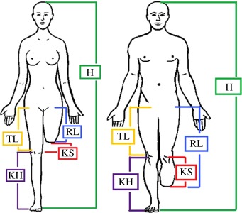 |
|
| patient force (very low, low, medium, high) | |||
| lifestyle (K1, K2, K3, K4) | |||
| pathologies (yes or no) | |||
| residual limb evaluation | amputation type (TF or TT) | ||
| amputation side (right, left or both) | |||
| residual limb stability (yes or no) | |||
| shape (cylindrical, conical or non-standard) | |||
| bone protuberances (widespread, on top) | |||
| skin conditions (sensitive, normal, scars, scratches) | |||
| tonicity (low, normal, good, very good) | |||
| anthropometric measures | height, H (mm) | ||
| foot length, FL (mm) | |||
| weight, W (kg) | |||
| residual limb length, RL (mm) | |||
| knee height, KH (mm) | |||
| thigh length, TL (mm) (only TF) |
The first group refers to general patient data mainly used for standard components selection. The second one regards parameters to evaluate the residual limb conditions and to create the three-dimensional model of the socket. The final one concerns anthropometric measures of the patient and residual limb. They are used to properly size the digital model of the patient, the standard components and the socket.
The biomechanical model of the amputee is defined at different levels of detail, depending on the task to be accomplished. For example, socket modelling and simulation require a detailed model of the residual limb (skin, bones and muscles).
Three main tools are used to create the biomechanical model (figure 2): a general-purpose human modelling system, medical images of the stump (obtained for example from MRI or CT) and an ad hoc software module for the three-dimensional reconstruction of the residual limb.
Figure 2.
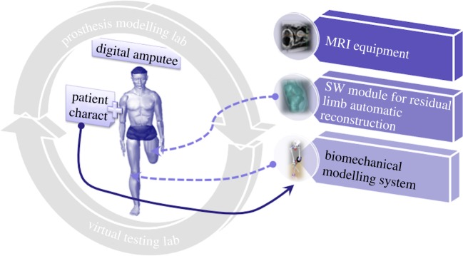
Digital patient. (Online version in colour.)
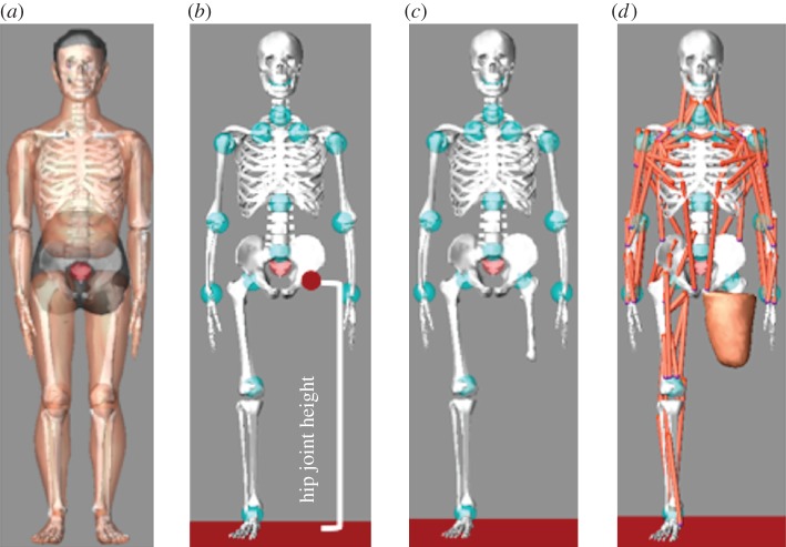
To create and simulate the patient's virtual human, we used LifeMOD (www.lifemodeler.com), a biomechanical simulation package based on MSC Adams. This allows a detailed biomechanical model of the human body to be created using rigid links connected through joints to simulate the skeleton and flexible elements to represent muscles, tendons and ligaments. Starting from a default virtual human (figure 3a), it is possible to generate a customized model modifying anthropometric data. We considered two reference avatars, one for a TF amputee (figure 3b) and another one for a TT amputee, which have to be customized for each specific patient. To characterize the patient's avatar, the following data are necessary: (i) patient's anthropometric data and (ii) digital model of the lower limb. This means that the biomechanical model of the amputee is realized in two steps: the first for avatar dimensioning and the latter for residual limb linking, as described in detail in the following sections.
Figure 3.
Avatar characterization: (a) standard virtual human model; (b) reference TF model; (c,d) patient's avatar. (Online version in colour.)
2.1. Avatar sizing
The correct dimensioning of the avatar is a key factor for the prosthesis set-up; this means that we need the patient's anthropometric data. We have distinguished between general patient data to properly size the avatar and stump measures to position and link the prosthesis to the avatar.
Some of them are included or can be derived from the above-mentioned patient characteristics (table 1). Some examples are hip joint (TF) or knee joint (TT) height, weight, height and foot length of the amputee. The remaining ones, such as shoulder height, can be acquired using a measuring tape or a motion capture system.
Once the necessary data have been entered and/or automatically acquired, LifeMOD automatically applies the first level of customization to the virtual amputee generating skeleton, masses, joints and soft tissues on the basis of anthropometric measures.
2.2. Residual limb linking
The virtual patient customized with the anthropometric data does not include the residual limb, meaningful for prosthesis design and for simulated gait analysis.
The detailed model of the residual limb, including external (skin) and internal (muscles and bones) parts, is built from medical images acquired using MRI. MRI is preferable to CT because it is the less invasive for the patient. Nevertheless, the final users of the platform are orthopaedic technicians without specific competences and skills in computer-aided tools (e.g. tools for medical image processing); therefore, we decided to implement a software module that automatically reconstructs the three-dimensional model of the stump without requiring human intervention and starting for the MRI volume. The implemented algorithm [15] first converts the MRI scan into a three-dimensional graph where nodes correspond to voxels and edges have weights representing the similarity of neighbours. Then, aggregative clustering is performed using features such as intensity and variance in the regions. Once the graph is segmented in different regions, the algorithm isolates internal bone voxels by size and shape analysis. The external surface, corresponding to the stump, is obtained by a threshold operation. Eventually, clusters belonging to bones and stump are automatically converted to NURBS surfaces that can be exported as IGES files. The final output is a three-dimensional geometric model (in neutral format), which permits CAD information exchange among the platform modules.
The residual limb model is imported and linked to the amputee model in two steps:
— the bone segment is first linked to the virtual hip (TF), as shown in figure 3c or to the knee (TT) using, respectively, the hip joint and the knee joint height;
— then, the residual limb soft tissues are accordingly positioned (figure 3d).
Once the customized avatar has been created, the designer can proceed to design the prosthesis on the basis of the biomechanical model and the patient's characteristics.
3. The prosthesis modelling laboratory
The PML permits the three-dimensional model of the prosthesis to be generated, crucial to virtually studying the prosthesis set-up and the patient's walking. It guides the technician during modelling and selection of standard and custom-fit components on the basis of the digital mock-up of the anatomical area involved, the patient's characteristics (e.g. anthropometric data) and the level of usage of the prosthesis. It integrates three main modules (figure 4):
— The Socket Modelling Assistant (SMA) [16], implemented ad hoc to model the socket directly around the digital residual limb, following rules and procedures, which replicate the activities performed in an orthopaedic laboratory.
— A simulation system, based on the finite-element method, to analyse the stump–socket interaction. At present, a commercial FEA system (Abaqus) is used, but our intention is to customize and integrate an open-source package.
— A commercial three-dimensional CAD system (SolidEdge) to configure the prosthesis and generate the three-dimensional models for the standard parts and final assembly.
Figure 4.
Prosthesis modelling lab. (Online version in colour.)
3.1. Socket design
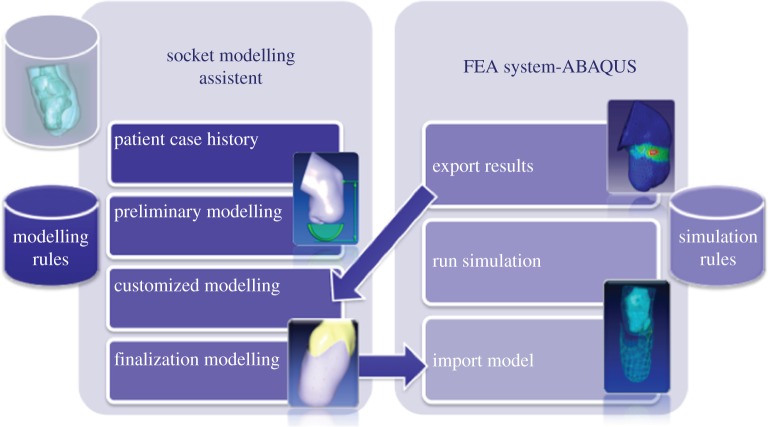
The first two modules, SMA and the FE commercial package, have been interfaced to work in a unique environment, the virtual socket laboratory (VSL). The interface has been realized using the object-oriented language Python. Figure 5 shows the high-level architecture of VSL.
Figure 5.
Virtual socket laboratory. (Online version in colour.)
Using SMA, the prosthetic can model the socket emulating the traditional procedures carried out during socket manufacturing. S/he is guided through the process in automatic or semi-automatic mode by the system itself. In fact, it embeds a set of design rules derived from analysis of the traditional process, such as where and how to modify the socket shape or automatically determine the socket thickness on the basis of the patient's characteristics [14].
Figure 5 shows the four main steps of the guided modelling procedure: patient case history, preliminary modelling, customized modelling and finalization modelling. Figure 6 portrays the user interface and an example of a residual limb.
Figure 6.
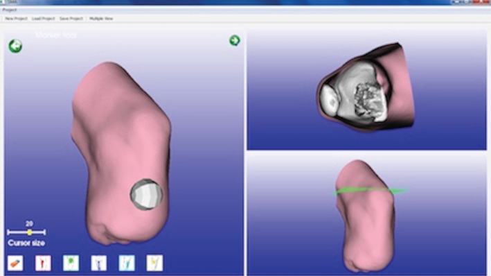
SMA user interface. (Online version in colour.)
The design process starts acquiring the patient's information traditionally considered by the technician (table 1), such as weight, muscles tonicity, skin conditions and residual limb stability. Then, s/he imports the stump digital model and sets the zones that require specific modifications.
During the second step, s/he generates a preliminary geometric model of the socket onto which other specific modifications will be applied to reach a functional shape. The main operations during this phase are carried out almost completely in automatic way according to patient characteristics and traditional process. For example, appropriate percentages for model scaling in relation to muscle tonicity were identified and collected in a table [14].
In the following step, the socket model is shaped directly on the digital stump model to be perfectly customized for each specific patient's anatomy. The system makes available interactive tools that permit tasks traditionally executed by the technician to be emulated. S/he starts to modify specific zones simulating the operations of adding and removing plaster. To this end, we divided these areas in two categories:
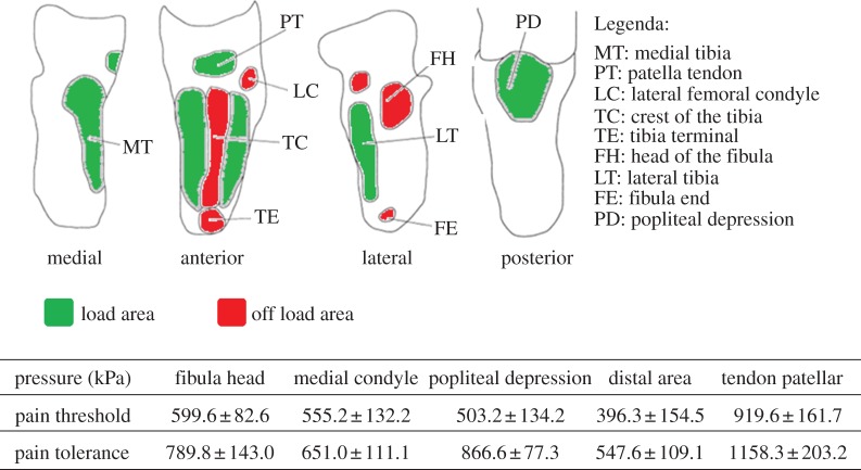
— Load zones where there are no bony protuberances or tendons and it is necessary to constrict the socket closer to the limb and create pressure to sustain the body weight.
— Off-load zones where there are bony protuberances or tendons and the socket does not have to press the limb and in the meantime not to be too wide because it could cause other physical problems.
The system also suggests the right percentage of material to be added or removed according to the ‘tonicity parameter’. The designer can decide to automatically apply values calculated by the system or modify the shape using a virtual tool, named ‘sculpt tool’. This is an interactive deformation tool, which permits the operations of adding and removing chalk material when the technician manipulates the positive plaster cast to be emulated. For example, in the off-load zones, the technician adds material from the positive plaster cast because the socket does not have to press the stump and can be quite loose, while in the load zones the plaster has to be removed in order to have a tight self-supporting socket.
Regarding the amount of chalk to be added or removed, we have identified eight manipulation levels, from 1 to 8 mm of thickness, to correlate with the stump tonicity.
Finally, the designer shapes the upper edge in an automatic or semi-automatic way, and the system suggests the final socket thickness. Typically, the prosthetic technician defines empirically the thickness on the basis of the patient's weight. In our system, we implemented the following simple formula derived from the technicians know-how:
A more sophisticated algorithm based on engineering knowledge and the mechanical properties of materials (e.g. carbon fibre socks) may be substitutes for this formula.
Once the socket has been modelled, the simulation to analyse pressure distribution, considered the most important evaluation parameter [17], is automatically executed. We derived the pain threshold (the minimum pressure that induces pain) and the pain tolerance (the maximum tolerable pressure) for most significant zones from Lee et al. [17] and Wu et al. [18].
As an example, figure 7 shows the critical zones for a TT amputee and related pain thresholds and tolerances.
Figure 7.
TT critical areas and related pain thresholds and tolerances [17,18]. (Online version in colour.)
The VSL embeds a set of simulation rules (e.g. input data, type of mesh, material etc.), we derived from the literature [5–8,19–21] looking for a compromise between results accuracy and computational costs. We adopted some simulation assumptions and rules, for example:
— Residual limb and socket geometry. Bones and soft tissues are merged to create a unique part without geometric discontinuity.
— Mesh. We adopted a free auto-meshing technique and explicit elements: 3-noded triangular (S3R) elements for the socket and 4-node tetrahedral (C3D4) for the residual limb, the latter increase their size in the internal regions.
— Material characterization. The mechanical properties of socket, bones and residual limb have been considered linear, homogeneous and isotropic and their values derived from the literature (table 2).
— Boundary conditions and loads. The upper surface of the residual limb is constrained. During the first two steps of the analysis, no external load is imposed, while in the last step the amputee's weight is applied to the centre of mass of the socket in a vertical direction. Socket movement and the constant static load are applied gradually during the analysis steps. Interaction between stump and socket is simulated with an automated surface-to-surface contact algorithm. Donning and adjustment steps are friction free, while during loading the friction coefficient is equal to 0.46.
— Analysis steps. The simulation is performed in three phases: (i) donning the residual limb imposing a pre-stress on the stump, (ii) an adjustment phase to achieve a better repositioning of the socket around the stump and to obtain maximum comfort, and (iii) application of the constant static load (amputee's weight).
Table 2.
Mechanical properties for linear analysis.
| material | density (kg dm–3) | Young's modulus (MPa) | Poisson's ratio |
|---|---|---|---|
| bones | 2 | 10 000 | 0.3 |
| soft tissue | 1.48 | 0.2 | 0.49 |
| socket | 7.8 | 15 000 | 0.3 |
SMA extracts input analysis from the patient's parameters (e.g. patient's weight and residual limb length), releases the files necessary to generate the FE model and chooses the script (written in Python language) for the analysis. The FE model is automatically created without human intervention. The prosthetist cannot modify FE model characteristics; however, if necessary, the system permits some parameters to be set, such as material properties. An Abaqus solver provides the analysis and generates the output file containing the pressure values, which are imported in SMA and visualized with a colour map. SMA evaluates pressure distribution and highlights the zones that should be modified by the prosthetic using SMA interactive tools. Then, the system re-executes the simulation until satisfactory results are achieved.
3.2. Standard components selection and prosthesis configuration
To select standard components and create the final assembly of the prosthesis a commercial three-dimensional CAD system has been adopted, namely SolidEdge. The prosthetic, guided by the system, selects the most appropriate standard components for the specific patient, and the system proposes possible configurations of the whole prosthesis according to the patient's characteristics.
For prosthesis modelling, we have divided the lower limb prosthesis into modules as follows [2,22,23] (figure 8):
— Socket module: includes liner, socket and socket adapters.
— Double adapter: includes double male or female pyramid adapters, which connect socket and knee in TF prosthesis, and can substitute a pylon in both TT and TF prosthesis.
— Knee module (only for TF amputees): includes prosthetic knee and knee adapters.
— Tube module: includes connecting pylon and tube adapters.
— Foot module: includes prosthetic foot, foot adapters and heel, also called ‘virtual heel’. Two key issues have been considered: components modelling/sizing and component selection.
Figure 8.
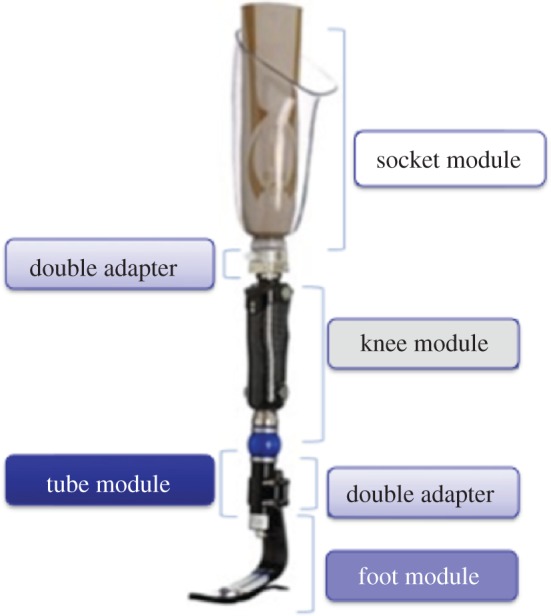
Prosthesis modules. (Online version in colour.)
Sizing and selection rules have been extrapolated from commercial catalogues provided by the main prosthetic brands and from technicians' know-how. As our purpose is to correctly assemble and check the virtual prosthesis and perform virtual gait analysis, we developed a library containing the three-dimensional parametric models for each module. We considered only the characteristics that affect static and dynamic behaviour, such as weight and joint position, and not the actual shape and appearance of components. Reference sizes have been taken from real ones and/or from data available in commercial catalogues. Particular attention has been placed on the foot and knee because they are the standard components responsible for the behaviour of the whole prosthesis, and their choice is a key factor to obtain a satisfying configuration. There is a huge variety of components on the market, and each manufacturer has their own models. For this reason, instead of taking into account specific models subjected to frequent variation, we identified a set of stable categories. As an example, for a TF amputee we identified main knee typologies, grouped as follows:
— Fixed: knee with locked centre of rotation during walking that can be manually unlocked when necessary.
— Monocentric: knees with one centre of rotation, divided for their functioning in self-brake, friction, pneumatic and hydraulic modes.
— Polycentric: knees with more centres of rotation also divided in self-brake, friction, pneumatic and hydraulic modes.
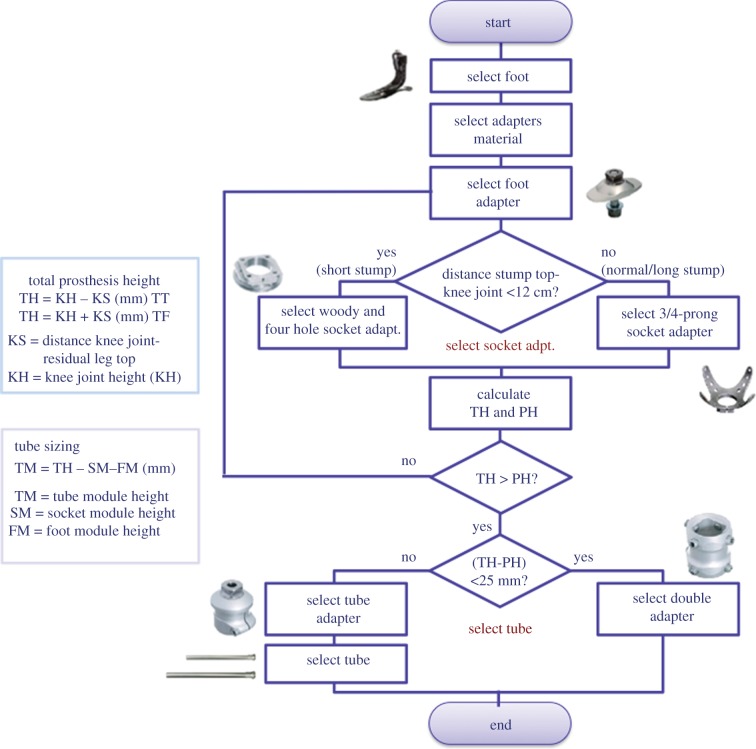
To select the proper components, we designed two configuration procedures (one for TT and another one for TF) and electronic sheets to automatically choose the appropriate components for each kind of amputee and size them accordingly. Figure 9 shows the configuration procedure for TT prosthesis and some examples of sizing rules.
Figure 9.
TT prosthesis configuration and sizing rules. (Online version in colour.)
The system automatically assembles all the possible combinations of the different selected parts and provides the technician with all the related bill of materials (BOMs). The user can select the most suitable one or change some components according to the patient's needs. While assembling the components, the system ensures that the alignment of the prosthesis is similar to the skeletal structure of the other leg. Traditionally, this operation is called bench alignment or plumb line alignment.
4. The virtual testing laboratory
The VTL permits the set-up and evaluation of prosthesis functionality simulating postures and movements of the virtual amputee with LifeMOD.
First of all, the digital patient (described in §2) has to wear the assembled prosthesis. This is imported from the virtual modelling lab and the correct positioning is obtained taking into account the prosthesis height and foot rotation with respect to the vertical line. In particular, the prosthetic foot has to be aligned to the other one and the socket has to hold the residual limb entirely.
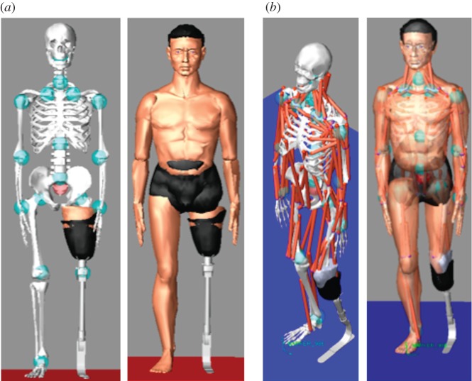
Figure 10 portrays either a TF or a TT avatar wearing the prosthesis.
Figure 10.
Amputee's avatar wearing the prosthesis: (a) TF and (b) TT. (Online version in colour.)
Now, the amputee's avatar can be used to perform static alignment and gait analysis during various activities. The underlying idea is to make available to the prosthetic technician a library of laws of motion specialized for patients wearing the prosthesis. To this end, it is necessary to acquire several of the patient's movements and postures during typical daily activities and then derive motion laws for non-natural joints.
At present, the approach has been tested using a markerless [24] motion capture system to determine the laws of motion relating to the patient's joint. Figure 11 shows the acquisition environment composed of the following:
— Four Sony-eye cameras, resolution 640 × 480 pixels at 60 Hz.
— The markerless motion capture technology iPi Desktop Motion Capture (http://www.ipisoft.com, accessed October 2012).
— A portable workstation Dell Precision M6500 with dual core CPU.
— A rehabilitation stair.
Figure 11.
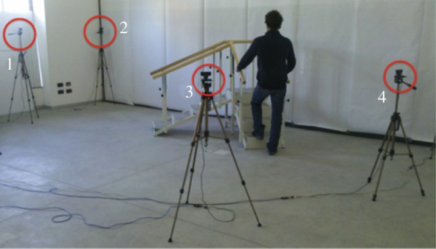
Markerless Mocap system. (Online version in colour.)
The adopted Mocap solution is low cost and accessible also to small orthopaedic laboratories. It does not require the patient to wear markers, because it is based on image and silhouette analysis. It automatically recognizes the different body segments and, then, calculates the position and orientation in three-dimensional space. In this environment, the patient has to perform typical daily activities, such as walking, sitting, stepping up/down, and so on. Obviously, precision of the tracking data is crucial and we are testing the quality of a webcam-based solution.
To reproduce movement with the patient's avatar, two issues have to be considered: data conversion and mapping of acquired data onto the amputee's avatar defined in the previous phase. Therefore, we developed two software modules that execute these tasks automatically. The first one converts acquired data from .BVH (Biovision Hierarchical Data) format used by iPi Mocap to the .SLF one used by LifeMOD, while the latter relocates parametrically the position of the joints acquired and used by Ipi Mocap in the LifeMOD human model.
To achieve accurate simulations of muscle and joint movement, an inverse dynamics simulation is first run to record angulations and muscle-contraction histories for the target body segments (links). ‘Motion agents’ are positioned on the model to drive the movement and ‘teach’ the joints and soft tissues how to move. In our case, to replicate the functionality of the residual limb, we have inserted ‘augmented motion agents’ linked to the prosthesis segments: three associated with the prosthetic foot, one with the tube below the knee representing the lower part of the leg, one with the knee (for TF) and another one with the socket. Once movements have been recorded in an inverse dynamics simulation, the compiled movement histories are ready to drive the forward dynamics simulations. Figure 12 shows the main steps of the acquisition and simulation procedure.
Figure 12.
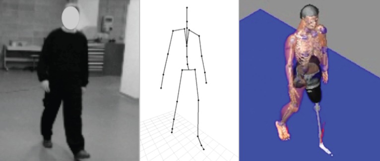
Acquisition and simulation procedure. (Online version in colour.)
5. Experimentation
Comprehensive validation of the system is quite complex and it is necessary for engineering the design platform. Moreover, it requires the active involvement of prosthetic technicians and patients.
At present, the proposed platform has been tested in three steps, at different levels, to validate progressively the new design process and develop computer-aided tools. The first step concerns the prosthesis configuration, the second one the prosthesis modelling process and the last one the whole design process, from modelling to testing.
Experimentation was realized in collaboration with the technical staff of an orthopaedic laboratory.
Tests were performed on workstations with the following technical characteristics: Intel Xeon W3505 2.53 GHz processor, 12.0 GB DDR3 1333 MHz RAM, Nvidia Quadro FX580 graphic unit, Windows 7 Ultimate 64 bit operating system.
5.1. Prosthesis configuration
The goal has been to verify the correctness of the knowledge-based configuration procedures as well as of selection and sizing rules adopted for standard components. Twenty amputees, 10 TF and 10 TT, were considered. Twenty patients were selected to cover the variation in all parameters. For each patient, we collected the four parameters necessary for the selection procedure: patient weight, lifestyle factors, residual limb length and patient force. Once the data had been acquired, the system automatically selected the most appropriate prosthetic feet and knees (for TF). The system is designed to facilitate the technician's choice by providing a list of the best performing components. This solution is preferred to a single result because some other factors (e.g. aesthetic or cultural aspects) may influence the final choice. The configurations suggested by the system have been compared with those ones identified by technicians following the traditional process.
For TT patients, seven configurations were in agreement with those proposed by the technicians, two partially (same component types but different ranking) and one failed (component selection was totally different). For TF patients, there was a high correspondence (90%) for knee selection, while foot selection was similar to TT one.
Even if there was not always a one-to-one correspondence, the technicians have satisfactorily evaluated the proposed configurations. They have appreciated the automated procedure and the advantage that different configurations can be easily generated and compared instead of concentrating only on few traditional ones.
The test cases, for which we did not find an appropriate correspondence, were explained by the fact that some patient's characteristics are not easily quantifiable. For example, for a middle-aged patient in good health but not motivated, a less-performing prosthesis is preferred since it would be easier to use, shortening the training time. Another example concerns an aesthetical components aspect: some people may prefer a small and slim component, while the system may choose a bigger but better performing component.
At present, we plan to introduce additional parameters, such as costs and aesthetic evaluation, in order to improve selection and component ranking.
5.2. Prosthesis modelling
In this case, the goal of experimentation has been to verify the prosthesis modelling approach and the results have been mainly qualitative. Two case studies have been considered: a TT amputee, 40 years old, 180 cm tall, and a TF one, 49 years old, 175 cm tall.
We started modelling the socket using the VSL; then, we proceeded configuring the whole prosthesis.
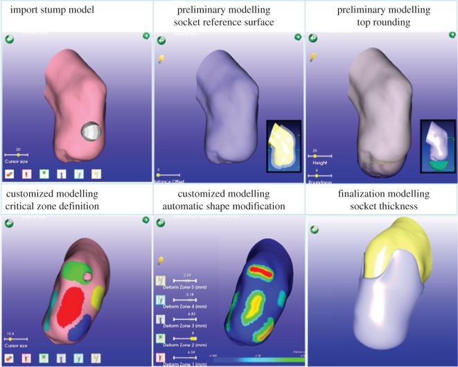
First, the stump geometry of both amputees was acquired and reconstructed as described in §2; then, the technicians of orthopaedic laboratory were asked to enter the amputee's data and create the three-dimensional socket model using SMA and following step-by-step the procedure and rules proposed by the system, according to the patient's characteristics. This is particularly important since most operations are dependent on the patient's characteristics, such as modification of critical areas (load and off-load zones) that significantly influence socket shape. SMA represents the kernel of the platform, and the main goal was to verify efficacy of the modelling/deformation tools and the feasibility of the knowledge-based approach to design a product, the socket, highly customized and characterized by a strict interaction with the human body. Figure 13 shows some modelling steps of the TT socket.
Figure 13.
Main socket modelling steps. (Online version in colour.)
Once the socket model has been created, the system automatically runs the simulation and visualizes the results. Pressure values are associated with a colour scale from blue to red, covering a range of fixed values ranging from 0 to 500 kPa. The areas that exceed the maximum are coloured grey. The limit value of 500 kPa represents the average pain threshold derived from the literature [17]. The system evaluates pressure values of critical regions and suggests necessary modification. Figure 14a shows the simulation results for the TT amputee. Pressure distribution is uniform and consistent, with the exception of the medial tibia region (523 kPa). To decrease the pressure in the medial tibia area (a ‘load’ region), the system can automatically modify the geometry of the socket in this zone or the prosthetic can modify it using the virtual tools available in SMA. Then, the system re-executes the simulation. Figure 14b shows the new pressure distribution where the pressure values are below the threshold.
Figure 14.

(a) Pressure distribution, (b) pressure distribution after modification. (Online version in colour.)
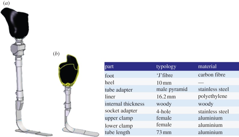
The next step was configuration of the whole prosthesis. On the basis of the patients' data, the system presents the technician with the appropriate components and adapters, sizing them and assembling all parts. For example, for the TF patient, the system automatically suggested two types of foot (mono-axial high energy and a multi-axial sandwich foot) and two knees (mono- and polycentric pneumatic knee). Once appropriate components had been confirmed, the system retrieved the three-dimensional parametric models of standard components from the database and assembled them together with the socket, obtaining the virtual prototype of the complete prosthesis. Figure 15 portrays the assembled prosthesis for the two case studies and BOM for the TT amputee.
Figure 15.
(a) Assembly of transfermoral and (b) TT prostheses. (Online version in colour.)
The new design approach and the results achieved have been positively evaluated. In particular, regarding the SMA, the technicians appreciated the interactive tools available to manipulate the socket shape and the level of assistance provided by the system. However, we have envisaged the need for some modifications to make the modelling tools easier to use, especially by non-computer-skilled users. For this purpose, we are now evaluating the usage of novel interaction tools, such as a haptic device, to make socket modelling more natural.
We plan to compare the generated three-dimensional socket models with the physical ones (hand-made by the technicians and currently used by the two patients) acquiring their geometry by reverse engineering techniques. The results of this comparison will permit us to verify whether the adopted approach, the system functionalities, the implemented rules, the operative modes and the level of knowledge embedded within the system are appropriate for the considered domain.
At the present stage of prototype development, we have not yet started an experimental campaign to fully validate the simulation results. We have planned experimental tests to acquire pressure values in the critical stump areas using innovative pressure sensors to assess both the simulation results and the FE model characterization. Moreover, indentation tests will be carried out to better characterize material properties.
Finally, prosthesis configurations (type of foot or knee, component sizing etc.) proposed by the system were in agreement with those realized by the prosthetics.
5.3. New design process: from modelling to testing
This test permitted us to verify the feasibility of the whole process, from modelling to simulation, and, in particular, the virtual testing approach.
The whole design process has been tested for the TF amputee. We started creating the patient's avatar as described in §2, acquiring his characteristics (e.g. anthropometric measures) and the residual limb morphology, both necessary to define the digital amputee. Then, the prosthesis was configured and modelled using the virtual prosthesis laboratory as previously described. Finally, we tested the VTL. The patient's avatar wearing the prosthesis was generated and two typical situations were simulated: patients walking along a flat regular floor and going up a step. To this end, the patient's motion was acquired with the considered markerless Mocap system (http://www.ipisoft.com, accessed October 2012). Figure 16 shows the TF avatar and the simulation of the amputee walking on a floor and going up a step.
Figure 16.
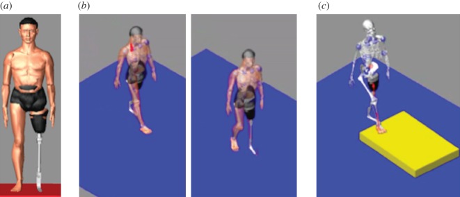
(a) TF avatar; (b) walking on a floor; (c) going up a step. (Online version in colour.)
Preliminary results are considered promising, but enhancements and system refinements are necessary. We have planned a campaign to acquire motion laws of joints during daily activities according to the patient's lifestyle. Then, a set of simulation tests will be performed to verify the performance of the framework and implemented procedures. As mentioned earlier, the goal is to develop a library of laws of motion specialized for the patient wearing the prosthesis and to be used to validate prosthesis functionalities. The motion capture system is considered adequate and no meaningful problems have been identified. To obtain a more precise acquisition we decided to use six cameras and experiment other low-cost systems already available on the market, such as MS Kinect sensor.
6. Conclusions
This paper presents the digital patient and the new software platform we have developed to design and configure lower limb prosthesis, both TF and TT, using only digital models and virtual tools. The digital patient is the core of the whole system around which the prosthetic technician designs and tests the virtual prosthesis guided by the system step by step along the proposed product development process. The platform integrates commercial packages, such as the Abaqus and LifeMOD, and ad hoc modules specifically developed, such as the SMA. Experimentation has been carried out with different test cases and involving a highly specialized orthopaedic laboratory in order to receive feedback directly from the end-users, validate efficacy and user-friendliness of the tools and verify the suitability of the digital patient.
Technicians appreciated the modelling tools for their ease of use. Configurations suggested by the system correspond to those obtained following traditional procedures, with the advantage that different configurations can be generated and compared more easily. The residual limb model has been considered adequate either for socket modelling or for simulation of the socket–residual limb interaction. With regard to the last topic, an experimental campaign will be implemented to better characterize material properties with indentation tests and to acquire real pressure values in the critical areas of the considered human part to validate the defined FE model. We are also considering the implementation of haptic interaction tools to support the socket modelling phase and make the socket-shaping procedure more natural and more similar to the traditional one. Preliminary tests have been carried out with a low-cost haptic device. The results are interesting and we plan to use a more sophisticated device, also taking into account low-cost solutions.
The virtual testing approach and the use of the amputee's avatar wearing the prosthesis have been judged promising, but further developments and enhancements are necessary to make them easily usable. We plan a campaign to acquire motion laws of joints during daily activities accordingly to the patient's lifestyle and to test different motion capture solutions. New devices, such as a brain–computer interface, are also under evaluation to be integrated within the platform.
The proposed platform should permit junior designers to be trained, reduce the number of prototypes and lower the psychological impact on the life of the patient; in fact, a computer-aided approach allows us to virtually carry out several steps in the traditional socket development process that are troublesome for amputees.
To conclude, even if we place attention on lower limb prosthesis, we feel confident about the extension of the platform to other kinds of prostheses, primarily for those in which patient-specific modelling is required, starting from three-dimensional anatomical models, although could adapt the MRI three-dimensional reconstruction, modelling and FE analysis stages. Conversely, the VTL is very focused on the analysis of amputee movements, even if we can customize the LifeMOD virtual avatar according to the specific problem, such as upper limbs amputees.
Acknowledgements
The authors want to thank the Fondazione Cariplo (Intesa Bank, Italy), which co-funded this research project. The authors would like to also thank Prof. Walter Albisetti (University of Milan) and Dr Omar De Bartolomeo (University of Milan), Stella Gabbiadini and Nino Mansi for their support and competence, and all the technical staff of Ortopedia Panini (Milan) for their valuable collaboration and great help to provide us with all necessary information about prosthesis development.
References
- 1.Smith DG, Michael JW, Bowker JH. (eds). 2004. Atlas of amputations and limb deficiencies: surgical, prosthetic, and rehabilitation principles. Rosemont, IL: American Academy of Orthopedic Surgeons [Google Scholar]
- 2.Marks LJ, Michael JW. 2001. Artificial limbs. Br. Med. J. 323, 732–735 10.1136/bmj.323.7315.732 (doi:10.1136/bmj.323.7315.732) [DOI] [PMC free article] [PubMed] [Google Scholar]
- 3.Bowker HK, Michael JW. 1992. Atlas of limb prosthetics: surgical, prosthetic, and rehabilitation principles. Rosemont, IL: American Academy of Orthopedic Surgeons [Google Scholar]
- 4.Dou P, Jia X, Suo S, Wang R, Zhang M. 2006. Pressure distribution at the stump/socket interface in transtibial amputees during walking on stairs, slope and non-flat road. Clin. Biomech. 21, 1067–1073 10.1016/j.clinbiomech.2006.06.004 (doi:10.1016/j.clinbiomech.2006.06.004) [DOI] [PubMed] [Google Scholar]
- 5.Faustini MC, Neptune RR, Crawford RH. 2006. The quasi-static response of compliant prosthetic sockets for transtibial amputees using finite element methods. Med. Eng. Phys. 28, 114–121 10.1016/j.medengphy.2005.04.019 (doi:10.1016/j.medengphy.2005.04.019) [DOI] [PubMed] [Google Scholar]
- 6.Frillici FS, Rissone P, Rizzi C, Rotini F. 2008. The role of simulation tools to innovate the prosthesis socket design process. In Intelligent production machines and systems (eds Pham DT, Eldukhri EE, Soroka AJ.), pp. 612–619 Dunbeath, UK: Whittles Publishing [Google Scholar]
- 7.Kistenberg R, Kondor S, Mate B, Brown E, Tawfik S, Terk M. 2010. Lower limb prosthetics. II. Analysis and design considerations of a prosthetic socket. In 13th ISPO World Congress, 2010, Leipzig, Germany Congress Lecture [3590–670]. See http://www.confairmed.de/e3470463/e3711658/e3729118/e3729336/Abstractcollectioneng2012_eng.pdf. [Google Scholar]
- 8.Dumbleton T, Buis AW, McFadyen A, McHugh BF, McKay G, Murray KD, Sexton S. 2009. Dynamic interface pressure distributions of two transtibial prosthetic socket concepts. J. Rehabil. Res. Dev. 46, 405–415 10.1682/jrrd.2008.01.0015 (doi:10.1682/jrrd.2008.01.0015) [DOI] [PubMed] [Google Scholar]
- 9.Goh JCH, Lee RS, Toh SL, Ooi CK. 2005. Development of an integrated CAD-FEA process for below-knee prosthetic sockets. Clin. Biomech. 20, 623–629 10.1016/j.clinbiomech.2005.02.005 (doi:10.1016/j.clinbiomech.2005.02.005) [DOI] [PubMed] [Google Scholar]
- 10.Coveney PV, Diaz V, Hunter P, Kohl P, Viceconti M. 2011. The virtual physiological human. Interface Focus 1, 281–285 10.1098/rsfs.2011.0020.2042-8901 (doi:10.1098/rsfs.2011.0020.2042-8901) [DOI] [PMC free article] [PubMed] [Google Scholar]
- 11.McFarlane NJB, Lin X, Zhao Y, Clapworthy GJ, Dong F, Redaelli A, Parodi O, Testi D. 2011. Visualization and simulated surgery of the left ventricle in the virtual pathological heart of the virtual physiological human. Interface Focus 1, 374–383 10.1098/rsfs.2010.0040 (doi:10.1098/rsfs.2010.0040) [DOI] [PMC free article] [PubMed] [Google Scholar]
- 12.Viceconti M, Taddei F, Cristofolini L, Martelli S, Falcinelli C, Schileo E. 2012. Are spontaneous fractures possible? An example of clinical application for personalised, multiscale neuro-musculo-skeletal modelling. J. Biomech. 45, 421–426 10.1016/j.jbiomech.2011.11.048 (doi:10.1016/j.jbiomech.2011.11.048) [DOI] [PubMed] [Google Scholar]
- 13.van der Linde H, Hofstad CJ, van Limbeek J, Postema K, Geertzen HB. 2005. Use of the Delphi Technique for developing national clinical guidelines for prescription of lower-limb prostheses. J. Rehabil. Res. Dev. 42, 693–704 10.1682/JRRD.2003.11.0172 (doi:10.1682/JRRD.2003.11.0172) [DOI] [PubMed] [Google Scholar]
- 14.Gabbiadini S. 2011. Knowledge-based design of lower limb prosthesis. PhD thesis, Industrial Engineering. University of Padova, Italy See http://paduaresearch.cab.unipd.it/3771/ [Google Scholar]
- 15.Felzenszwalb FF, Huttenlocher DP. 2004. Efficient graph-based image segmentation. Int. J. Comp. Vis. 59, 167–181 10.1023/B:VISI.0000022288.19776.77 (doi:10.1023/B:VISI.0000022288.19776.77) [DOI] [Google Scholar]
- 16.Colombo G, Facoetti G, Gabbiadini S, Rizzi C. 2010. Knowledge-based system for guided modeling of sockets for lower limb prostheses. Comput. Aided Design Appl. 7, 723–737 (doi:10.3722/cadaps.2010.723–737) [DOI] [Google Scholar]
- 17.Lee WC, Zhang M, Mak AF. 2005. Regional differences in pain threshold and tolerance of the transtibial residual limb: including the effects of age and interface material. Arch. Phys. Med. Rehabil. 86, 641–649 10.1016/j.apmr.2004.08.005 (doi:10.1016/j.apmr.2004.08.005) [DOI] [PubMed] [Google Scholar]
- 18.Wu CL, Chang CH, Hsu AT, Lin CC, Chen SI, Chang GL. 2003. A proposal for the pre-evaluation protocol of below-knee socket design: integration pain tolerance with finite element analysis. J. Chin. Inst. Eng. 26, 853–860 10.1080/02533839.2003.9670840 (doi:10.1080/02533839.2003.9670840) [DOI] [Google Scholar]
- 19.Mak AF, Zhang M, Boone DA. 2001. State-of-the-art research in lower-limb prosthetic biomechanics–socket interface: a review . J. Rehabil. Res. Dev. 38, 161–174 [PubMed] [Google Scholar]
- 20.Baars ECT, Geertzen JHB. 2005. Literature review of the possible advantages of silicon liner socket use in trans-tibial prostheses. Prosthet. Orthotics Int. 29, 27–37 10.1080/17461550500069612 (doi:10.1080/17461550500069612) [DOI] [PubMed] [Google Scholar]
- 21.Tonuk E, Silver-Thorn MB. 2004. Nonlinear viscoelastic material property estimation of lower extremity residual limb tissues. J. Biomech. Eng. Trans. ASME 126, 289–300 10.1115/1.1695575 (doi:10.1115/1.1695575) [DOI] [PubMed] [Google Scholar]
- 22.Seymour R. 2002. Prosthetics and orthotics lower limb and spinal. Philadelphia, PA: Lippincott Williams & Wilkins [Google Scholar]
- 23.Kelly BM, Pangilinan PH, Rodriguez GM, Bodeau VS. 2009. Lower limb prosthetics. See http://emedicine.medscape.com/article/317358-overview
- 24.Bray J. 2012. Markerless based human motion capture: a survey (accessed October 2012) See http://visicast.co.uk/members/move/Partners/Papers/MarkerlessSurvey.pdf


