

Abstract
A multitude of neuroengineering challenges exist today in creating practical, chronic multichannel neural recording systems for primate research and human clinical application. Specifically, a) the persistent wired connections limit patient mobility from the recording system, b) the transfer of high bandwidth signals to external (even distant) electronics normally forces premature data reduction, and c) the chronic susceptibility to infection due to the percutaneous nature of the implants all severely hinder the success of neural prosthetic systems. Here we detail one approach to overcome these limitations: an entirely implantable, wirelessly communicating, integrated neural recording microsystem, dubbed the Brain Implantable Chip (BIC).
I. Introduction
Neuroscientists and engineers together have made remarkable progress in unraveling the machinery, and subtlety, of the primate brain. From this has emerged a fascinating contemporary technical and ethical challenge: Can we turn thoughts into actions? Extraordinary work has been done showing that indeed this type of bridge can be made, and motor outputs can be deciphered from limited information extracted from the brain [1], [9], [10], [12]. However, the question remains as to how wide the lanes of this bridge can and should be. Truly understanding the brain will require sensing across a vast range of temporal and spatial scales (low frequency potentials, 1-40 Hz, to action potentials, ~1000 Hz – LFPs to spikes). This paper selectively highlights our current research, which aims at developing a wireless link to the brain via implantable active microchips.
There are millions of patients who suffer from serious neurological insult and illness, whose quality of life is substantially compromised even while the brain itself is completely functional. Society, and the individual, stands to have much to gain from the development of devices that can directly record and translate cortical signals into functional motor or other output. This translation has been the drive behind the Neuromotor Prosthesis field (NMP) and is the fundamental reason for the development of the BIC microsystem.
Implantable cortical NMP systems present many challenges, including the development and integration of ultra-low-power microelectronic chips onto the sensing multielectrode array (MEA), the modality of on-board broadband telemetry, and the power delivery since such a system necessitates active electronics. Almost paramount to these challenges is the encapsulation and biocompatibility of an electrically active, multi-element implant. In this paper, we describe our approach and development status towards these challenges, highlighting design choices and recent results of wireless data transmission from an implanted microsystem in a fully awake rhesus macaque monkey over a period of 14 days.
This paper is organized into the following sections: Section II describes the design choices taken and the fabrication process, including MEA-amplifier integration, encapsulation, and ex vivo (benchtop) testing. Section III details acute rodent, ad-hoc primate, and sub-chronic primate experiments providing implementation details from each design. Section IV presents our results from wireless data transmission of the BIC microsystem.
II. Design Choices and Fabrication of the BIC
A. Substrate Design
Flexibility, processability, and biocompatibility are the greatest deciding factors when choosing a substrate to build an implantable microsystem onto. In addition, due to the sensitivity of the cortex to temperature change and intracranial volume constraints (we limited ourselves to 1 °C and 1 mm in thickness above the cortex), we needed to take into account the distribution of components over the cortical landscape. We employ a “two island” concept where the sensing components are separated from the digitizing and telemetry components. The “frontend” (intracranial) section contains only the amplifier and microelectrode array. A thin substrate interconnect bridges the frontend to the “backend” (extracranial), which, is where digitization and telemetry occur.
For this microsystem we chose to use Kapton (a polyimide – constructed at Microconnex, inc. Seattle, WA). At a thickness of 0.0005”, CuNiAu traces of 0.001, and double-sided lamination (Kapton) of 0.001” each, the entire substrate achieved a very flexible, as well as durable structure. These substrate materials have been successfully used for some time in retinal prosthetics [14].
B. Amplifier and MEA – Integration
We have developed an ultra-low power, easily integrateable CMOS preamplifier array with integral multiplexing and measured noise levels (in saline) of 9 uVRMS. This 16-channel, fully scalable CMOS amplifier array has an average gain of 44 dB, bandwidth from 10 Hz to 7.3 kHz, and an average power consumption of 52 μW/preamplifier (see table 1).
TABLE I. Power Consumption of BIC Components.
Power consumption of components in the BIC microsystem based on 3.3 VDC delivered to the system. The overall amplifier power consumption here is very low, compared to the 80 μW per amplifier presented by Harrison [5].
| Component | Consumption | Unit |
|---|---|---|
| ADC (AD7495) | 4.5 | mW |
| Preamplifier (M4b) | 52 | uW |
| Amplifier overall (M4b) | 1.3 | mW |
| Controller | 5 | mW |
| VCSEL | 2 | mW |
| Total | 12.32 | mW |
This chip was designed to be integrated directly on the back of the MEA (Blackrock inc., Salt Lake City. UT) in order to minimize the distance raw analog signals must travel before amplification. We have chosen to use a flip-chip integration strategy based on a specific conductive epoxy (H20E, Epoxy Technology, Inc.) for the electrical interface between the microelectrode array and the CMOS chip. Conductive silver epoxy is applied to the pads (80 μm × 80 μm) of the CMOS chip by a pin stamping technique so that approximately 150 μm diameter and 50 μm high epoxy dots are deposited with <10 μm placement precision. A semi-automatic, epoxy dot-stamping machine minimizes any potential stress applied to the assembly. The 16-element MEAs were bonded to the CMOS chip using a high accuracy, flip-chip bonder (RD Automation, Inc, model M9) with “zero pressure” epoxy bump bonding. The die bonder incorporates an optical auto-collimator, a critical component to ensure absolute parallelism between the entire microelectrode array and amplifier chip during mating.
C. Infrared Telemetry
Data in the microsystem begins as input to the amplifier. The amplifier output is then multiplexed in time domain and sent to the backend through conductive traces on the flexible Kapton substrate connecting the frontend and backend (the tether). On the backend, the multiplexed analog data is transformed into a serial digital stream by the ADC, and then is converted into digital stream of pulses by a vertical cavity surface-emitting laser (VCSEL) controlled by the digital controller IC. The light pulses are received in free space by a Silicon PIN photodiode (S6967 from Hamamatsu Inc.), which converts the pulse code modulated light signal into a digital stream of electrical pulses (a TTL signal) for realtime reconstruction and storage of the neural signal recordings in an PC though a custom designed digital interface. Transmission through primate skin causes scattering, but the photodiode is still able to pickup the digital stream when placed within ~2 mm of the skin surface. Optimization of the beam pickup is currently underway.
D. Encapsulation
The entire microsystem of fig. 1 (bottom) is presently encapsulated in polydimethylsiloxane (PDMS) for electrical isolation and mechanical flexibility. Surgical implant considerations require careful control of PDMS thickness to maintain flexibility in the tether and to prevent buildup over the electrode array. For images of the structure after encapsulation, see Refs. [6], [7]. The main functions of the encapsulation are to ensure (i) that electrical leakage current to the adjacent tissue is minimized, and (ii) ionic leakage from the tissue to the electronic components is less than 10pA. For chronic implant applications, this presents a formidable challenge for all researchers in the field of implantable neural prosthetics. We view our initial approach, using PDMS (NuSil R-2188), as a useful starting point for sub-chronic or short-term (1 - 3 months) in-vivo animal testing. In addition, we have designed and implemented an encapsulation test unit (ETU), which, simulates the topographical, thermal, and electrical stresses put on the encapsulent to test leakage current and component functionality over extended periods of soak time. This test system allows us to evaluate and characterize potential encapsulants under realistic conditions.
Fig. 1.
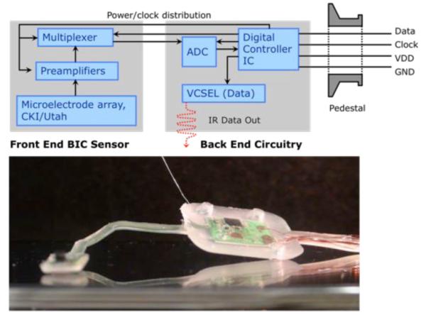
A Schematic of Brain Implantable Chip with pedestal and image of system encapsulated in NuSil R-2188 for saline testing. The schematic (top) shows the data flow from the MEA sensor, through the amplifier and digitizer, and eventually bifurcated in the controller to be delivered wirelessly via IR and wired on the data-out line.
E. Scalability
While the system expressed here attains 16 (one channel, 16, carrying the frame synchronization word to align the received data stream), it has been designed from the outset to be expanded without major redesign – specifically for a 100-channel MEA platform (work under way). A 4 × 4 MEA allowed for simpler integration and faster turn-around time of devices. However, it is clear from previous work that more units, and in effect, more channels, are required to accurately decode intention in a high-dimensional space, such as in representing wrist and arm joint angles. Beyond increasing the number of channels for a given MEA, the layout of our BIC system also allows, in principle, its extension to a number of cortical ‘frontend’ implants (various recording sites) which are connected to a common subcutaneous backend telemetric unit.
III. Implementations of the BIC Microsystem
Two variations of the microsystem have been fabricated to serve specific tasks. In addition, various forms of the “primate microsystem” have been used in a rodent model to validate the frontend insertion parameters, which are in fact different from published values for the pneumatic insertion of just a MEA with wire bundle into primate cortex (higher pressure, 25-30 psi).
A. Screw-top Microsystem - External
For the evaluation of the BIC electronics and functionality, it made sense to develop a system that could take input directly from the NeuroPort implant (passive 100 electrode array with pedestal connector – see Refs. [1], [7], and [10]). This would allow us to test the performance of all critical components (signal-noise levels of the amplifier, wireless telemetry, etc.) on signals from a primate with a well-characterized implant. The system we developed is called the Brown Neurocard (BNC) and has been recently detailed in [11]. It has been used on 3 different primates with great success. This device has and will continue to serve as an excellent test platform with direct access to neural signals without reimplantation of the primate.
B. Primate Microsystem - Implantable
As shown in fig. 1 (bottom), the implantable primate microsystem is encapsulated in PDMS and has an “L” shape, which was designed to fit the cortex of the primate in study. The electrodes of the microsystem frontend were inserted ~1 mm into the arm area of MI. The tether was tunneled through the craniotomy, allowing the backend to sit atop the skull where it was fixed with titanium screws. A titanium pedestal was used to allow power, clock and ground lines to enter the system and to allow data lines to exit (data lines were used for verification of optical data). In future models of this system, power and clock will be delivered by RF inductive coupling allowing for wireless power transmission.
All data reported in this paper was recorded from the primate microsystem and was recorded via transcutaneous optical link from an implanted device.
IV. Results of Primate Sub-Chronic Study
Seven days after implantation, we began to see spiking activity on several channels (one in particular is shown in fig. 2). After the first day of recording, the number of channels with spiking units varied from 8-12. In addition, several channels showed more than one unit on a given session. It was unclear and remains unverified if the same units were being recorded on each channel throughout the two-week period. For example, on day 8 channel 14 showed clear activity while on day 9 it presented none. Below in fig. 3 we show average waveforms from all recording channels. Although the data shown is the filtered, windowed waveform, it is critical to remember that we are recording and transmitting broadband (10 Hz – 7300 Hz) data which may contain other neural signals, besides spikes, that we may be interested in.
Fig. 2.
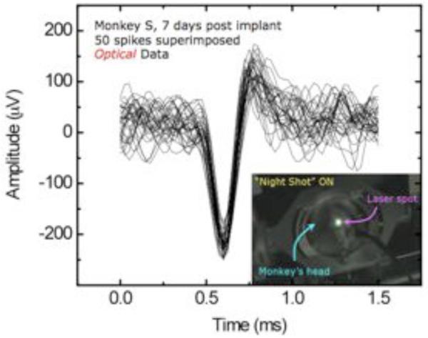
Superimposed traces recorded from fully implanted neural sensing microsystem with transcutaneous optical data link, 7 days after implantation. On this particular day of recording, 5 channels showed spiking activity. A maximum of channels recording occurred on day 11 with 12 of 15 channels showing spikes. Total data above collected over 15 seconds.
Figure 3.
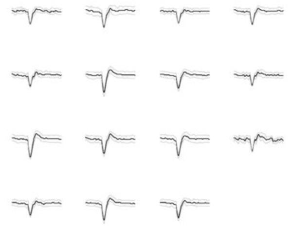
Overlays (from 20-60 spikes) from all 15 channels recorded wirelessly from primate motor cortex while primate performed grasping tasks.
Once initial characterization was completed of the microsystem, the primate was trained to sit in a chair and grasp the trainer’s hand. During this exercise, we recorded neural activity over 7 trials. The spiking activity correlated well with the timing of the movement – raster plots shown in fig. 4. These results show clearly that (i) our system is able to transmit broadband data transcutaneously (wirelessly) out to a receiver, and (ii) that the data being transmitted is in fact neural in origin and movement dependant.
Fig. 4.
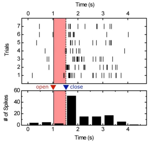
Raster (top) and histogram (bottom) of grasp event (red, pr shaded if black and white print). This particular neuron appeared to be particularly correlated with grasp relaxation, i.e. when the primate released its grip.
V. Conclusion and Continued Work
While reporting progress where an implantable microsystem has been tested in a non-human primate on the order of 1 month, many challenges remain on the path to a fully implantable, neural processing platform for chronic, long-term human use. Among these are the encapsulation (packaging) of the implantable units to ensure extended animal and patient safety and biocompatibility. Specifically for the BIC microsystem reported here, we are presently developing surgical and post-operation procedures for our tabletop tested device with transcutaneous inductive RF power delivery to complete the truly wireless cortical neural interface in non-human primates and eventually human patients.
ACKNOWLEDGMENT
The authors would like to thank John Mislow M.D., Ph.D. for his constant surgical and clinical support, Leigh Hochberg M.D., Ph.D. for his guidance, John Simeral Ph.D. and Naveen Rao for their decoding and statistical processing support, as well as James Harper III, V. M. D., and the veterinary staff for their continued support and care for both research and animal welfare.
This work was supported in part by the National Institute of Health (NIBIB and NCMRR/NICHD) under Bioengineering Research Partnership Program (IR01EB007401-01), the Office of Naval Research under Neuroengineering Program (N0014-06-0185), and the National Science Foundation under Biophotonics Program (0423566).
Contributor Information
David A. Borton, Division of Engineering, Brown University, Providence, RI 02912 USA.
Yoon-Kyu Song, Division of Engineering, Brown University, Providence, RI 02912 USA.
William R. Patterson, Division of Engineering, Brown University, Providence, RI 02912 USA.
Christopher W. Bull, Division of Engineering, Brown University, Providence, RI 02912 USA
Sunmee Park, Division of Engineering, Brown University, Providence, RI 02912 USA.
Farah Laiwalla, Division of Engineering, Brown University, Providence, RI 02912 USA.
John P. Donoghue, Department of Neuroscience and head of the Brain Science Program of Brown University, Providence, RI 02912 USA
Arto V. Nurmikko, Division of Engineering, Brown University, Providence, RI 02912 USA.
REFERENCES
- [1].Hochberg LR, Serruya MD, Friehs GM, Mukand JA, Saleh M, Caplan AH, Branner A, Chen D, Penn RD, Donoghue JP. Neuronal ensemble control of prosthetic devices by a human with tetraplegia. Nature. 2006;442:164–171. doi: 10.1038/nature04970. [DOI] [PubMed] [Google Scholar]
- [2].Bai Q, Wise KD. Single-unit neural recording with active microelectrode arrays. IEEE Trans. Biomed. Eng. 2001;48(8):911–920. doi: 10.1109/10.936367. [DOI] [PubMed] [Google Scholar]
- [3].Mojarradi M, Binkley D, Blalock B, Andersen R, Uslhoefer N, Johnson T, Del Castillo L. A miniaturized neuroprosthesis suitable for implantation into the brain. IEEE Trans. Neural Syst. Rehabil. Eng. 2003;11:38–42. doi: 10.1109/TNSRE.2003.810431. [DOI] [PubMed] [Google Scholar]
- [4].Rizk M, Obeid I, Callender SH, Wolf PD. A single-chip signal processing and telemetry engine for an implantable 96-channel neural data acquisition system. J Neural Eng. 2007;vol. 4:309–21. doi: 10.1088/1741-2560/4/3/016. [DOI] [PubMed] [Google Scholar]
- [5].Harrison R, Watkins P, Kier R, Lovejoy R, Black D, Normann R, Solzbacher F. A Low-Power Integrated Circuit for a Wireless 100-Electrode Neural Recording System. International Solid State Circuits. 2006 Feb; Session 30, Silicon for Biology. [Google Scholar]
- [6].Patterson WR, Song Y-K, Bull CW, Deangelis AP, Lay C, McKay JL, Nurmikko AV, Donoghue JD, Connors BW. A Microelectrode/Microelectronic Hybrid Device for Brain Implantable Neuroprosthesic Applications. IEEE Trans. Biomed. Eng. 2004;51:1845–1853. doi: 10.1109/TBME.2004.831521. [DOI] [PubMed] [Google Scholar]
- [7].Song Y-K, Patterson WR, Bull CW, Beals J, Hwang N-J, Deangelis AP, Lay C, McKay JL, Nurmikko AV, Fellows MR, Simeral JD, Donoghue JP, Connors BW. Development of a Chipscale Integrated Microelectrode/Microelectronic Device for Brain Implantable Neuroengineering Applications. IEEE Trans. Neural Rehabil. Eng. 2005;13:220. doi: 10.1109/TNSRE.2005.848337. [DOI] [PubMed] [Google Scholar]
- [8].Kipke DR, Vetter RJ, Williams JC, Hetke JF. Silicon-substrate intracortical microelectrode arrays for long-term recording of neuronal spike activity in cerebral cortex. IEEE Trans. Neural Syst. Rehab. Eng. 2003;vol. 11:151–155. doi: 10.1109/TNSRE.2003.814443. [DOI] [PubMed] [Google Scholar]
- [9].Georgopoulos AAP, Kalaska JF, Caminiti R, Massey JT. On the relations between the direction of 2-dimensional arm movements and cell discharge in primate motor cortex. J. Neuroscience. 1982;2(11):1527–37. doi: 10.1523/JNEUROSCI.02-11-01527.1982. [DOI] [PMC free article] [PubMed] [Google Scholar]; Circuits. 2003 Jun;38:958–965. [Google Scholar]
- [10].Vargas-Irwin C, Donoghue JP. Automated spike sorting using density grid contour clustering and subtractive waveform decomposition. J Neuroscience Methods. 2007 doi: 10.1016/j.jneumeth.2007.03.025. [DOI] [PMC free article] [PubMed] [Google Scholar]
- [11].Song Y-K, Borton DA, et al. Active Microelectronic Neurosensor Arrays for Implantable Brain Communication Interfaces. IEEE Trans. Neural Rehabil. Eng. 2009 doi: 10.1109/TNSRE.2009.2024310. in press. [DOI] [PMC free article] [PubMed] [Google Scholar]
- [12].Chestek CA, Kier RJ, et al. HermesC : RF Wireless Low-Power Neural Recording System for Freely Behaving Primates. IEEE Circuits and Systems. 2008:1749–1755. [Google Scholar]
- [13].Jackson A, Moritz CT, Fetz EE. Correlations between the same motor cortex cells and arm muscles during a trained task, free behavior, and natural sleep in the macaque monkey. J Neurphysiol. 2007;vol. 97:360–374. doi: 10.1152/jn.00710.2006. [DOI] [PubMed] [Google Scholar]
- [14].Rizzo J, Wyatt J, Loewenstein J, Kelly S, Shire D. Methods and Perceptual Thresholds for Short-Term Electrode Stimulation of Himan Retina with Microelectrode Arrays. Inv. Ophthal. & Vision Sci. 2003;vol. 44(no. 12):5355–5361. doi: 10.1167/iovs.02-0819. [DOI] [PubMed] [Google Scholar]