Abstract
Multipolar transitions other than electric dipoles are generally too weak to be observed at optical frequencies in single quantum emitters. For example, fluorescent molecules and quantum dots have dimensions much smaller than the wavelength of light and therefore emit predominantly as electric dipoles. Here we demonstrate controlled emission of a quantum dot into multipolar radiation through selective coupling to a linear nanowire antenna. The antenna resonance tailors the interaction of the quantum dot with light, effectively creating a hybrid nanoscale source beyond the simple Hertz dipole. Our findings establish a basis for the controlled driving of fundamental modes in nanoantennas and metamaterials, for the understanding of the coupling of quantum emitters to nanophotonic devices such as waveguides and nanolasers, and for the development of innovative quantum nano-optics components with properties not found in nature.
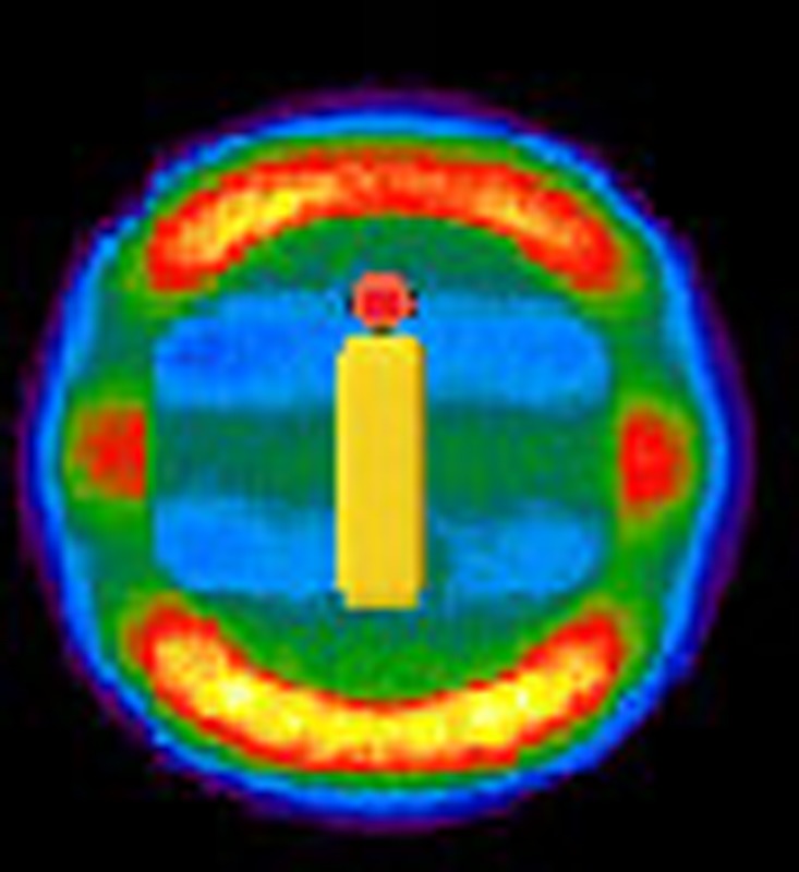 Nanoantennas provide improvements in detection and fluorescence of nanoscale objects, which are usually limited to electric dipole radiation. By exploiting coupling to nanowire antennas, Curto et al. show controlled multipolar emission of a quantum dot, offering a novel multipolar photon source.
Optical antennas offer unprecedented possibilities for the interaction of light with nanoscale matter1,2. Emission and absorption can be controlled by near-field coupling to a properly designed antenna mode. Nanoantennas based on dipolar resonances have already been exploited to improve single-molecule detection3, brighten single-photon sources4,5 and direct fluorescence6. Ultimately, having access to all possible multipolar terms in the field expansion, beyond the dipole, provides complete control over optical fields to engineer electromagnetic parameters like phase, polarization state, directions of radiation and optical angular momentum.
Most optical antennas are based on short metal nanowires. In contrast, longer nanowires act as waveguides for surface plasmons7 and coupling of quantum emitters results in confined transport of the emitted photons8,9. On the other hand, optical antennas aim to maximize the power radiated by quantum emitters to the far field into well-defined modes of the light field6,10. Nanowire antennas are an ideal platform to explore single-photon emission beyond usual electric dipole radiation thanks to the higher-order resonances of such nanorod antennas. These resonances have been studied using various techniques, mainly capitalizing on spatial mapping11,12,13,14,15,16,17,18,19,20.
Here, we demonstrate multipolar radiation of quantum dots (QDs) by coupling to multipolar resonances of nanowire antennas of increasing length, with alternating symmetry and multipole parity. The measured angular patterns and polarization states are reproduced by a one-dimensional model, and the underlying nature of the resonances is revealed by a multipolar expansion, showing controlled dipolar, quadrupolar, octupolar and higher multipolar character in the photon emission. Our results provide a first deterministic realization of the resonant interaction of quantum emitters with a variety of nanowire antenna modes of even and odd symmetries, which are fundamental building blocks in nano and quantum optics.
Results
Coupling a QD to a nanowire antenna
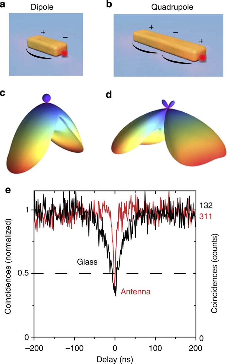
Intuitively, nanowires can be regarded as cavities for surface plasmons; at resonance, the oscillating surface charge and current distributions along the nanowire display stationary nodes21,22,23,24,25. We model the nanowire as a one-dimensional resonator24. We label the order of the different resonances with j, indicating the approximate number of half-wavelengths contained in the resonator or, equivalently, the current maxima along the antenna (Fig. 1a). The emission properties of these modes and their near-field interaction with quantum emitters are governed by the symmetry and spatial distribution of the characteristic currents for each mode. For example, the lowest order mode, j=1, has odd charge symmetry (Fig. 1a) and its current distribution creates a dipole source. The j=2 mode has even symmetry, with a zero net dipole moment, and resembles a longitudinal quadrupole. Hence, j=1 corresponds to a half-wave dipole antenna, whereas j=2 is a full-wave, end-fed quadrupole antenna. As a first approximation, we expect that the angular radiation patterns of these two lowest order antenna modes are point dipoles and point quadrupoles (Fig. 1c).
Figure 1. Single quantum dots coupled to nanowire antenna modes.
(a,b) A QD is positioned at the end of a metal nanowire. The first two resonant modes have opposite symmetries in surface charge distribution and current along the antenna. Charge sign and current magnitude are sketched. (c,d) Angular radiation patterns of an electric point dipole and a point quadrupole oriented parallel to the longitudinal axis of the antenna above a glass substrate. Both patterns differ radically in direction and width of the lobes, with most radiation emitted into the lower half-space (substrate). The emission wavelength is 800 nm and the emitters are 15 nm above the substrate. (e) Photon anti-bunching measurements comparing the inter-photon delay of single photons emitted mostly by a single QD on glass (black) and coupled to a dipolar antenna (red). Single-photon emission is evidenced by a dip below 0.5 in coincidences. The total accumulation time was 50 min and the time resolution was 1.184 ns. Background contributions to the coincidences were not subtracted. Higher transition rates (narrower anti-bunching dip) are due to resonant coupling to the antenna.
Each multipolar resonance can be locally driven at points where the coupling between quantum emitter and antenna is efficient. The electric mode density is high at the ends of a nanowire regardless of the symmetry of the resonant mode. Therefore, a point source (electric dipole) at the end of a nanowire couples to all possible resonant modes, breaking the symmetry that might prevent access by far-field illumination, and encompassing both sub- and super-radiant modes irrespective of symmetry24,26. Our approach relies on positioning colloidal QDs with nanometre accuracy at the end of each nanowire through a combination of two steps of electron beam lithography and chemical functionalization6. With our method, we obtain arrays of antennas with typically one to three QDs per antenna at a predefined position. Photon anti-bunching measurements show a dip around zero inter-photon delay time (Fig. 1e, red line) characteristic of single-photon emission27,28,29, confirming that as few as a single QD can be attached to an antenna. Coupling to the antenna increases transition rates, which include radiative, non-radiative and excitation rates, resulting in a narrower dip than for a single QD on bare glass (black line).
Multipolar emission of hybrid quantum-emitter–antenna systems
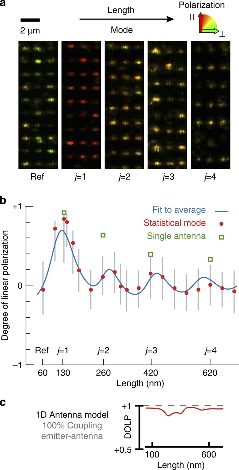
First, we identify the antenna resonant lengths from the change of polarization of the emission30 of QDs when coupled to nanowires of increasing length. To this end, we record confocal photoluminescence images of arrays of identical antennas with lengths from 60 to 900 nm. The emission is detected in two polarization channels, parallel and perpendicular to the long axis of the wires, with signals I|| and I┴, respectively. The polarization of the emission depends on the mode of the antenna, evolving from linear polarization along the antenna to unpolarized emission for increasing order resonances (Fig. 2a). For quantitative analysis, we define the degree of linear polarization: DOLP=(I||−I┴)/(I||+I┴). By taking statistics over ~200 antennas per length, we observe clear oscillations in polarization degree as a function of antenna length due to the evolution on and off resonance (Fig. 2b). Yet, linearly polarized emission along the antenna, with DOLP≈1, is expected for an oscillating current on a line and predicted by our resonator model even off resonance (Fig. 2c). The observed oscillations in polarization in Fig. 2b are due to partial coupling of the QDs to the antennas, namely, a fraction of the emission does not interact with the antenna mode. The relative weight of the contributions of the polarized antenna mode and an unpolarized, uncoupled background varies as the antenna is tuned to resonance with the QD emission. The background comprises both direct, uncoupled QD emission and luminescence of the gold antennas themselves. Note that the emission of even a single QD is predominantly unpolarized because of the planar degeneracy in transition dipole moment of our semiconductor nanocrystals31,32. The resonances in polarization are thus attributed to the resonant modes j, and indicate the best overlap between antenna mode and the QD luminescence spectrum, centred around 800 nm.
Figure 2. Polarization oscillations map the resonant modes of antennas of increasing length.
(a) Confocal luminescence microscopy images of arrays of identical antennas of increasing length. The colour code reflects the DOLP of the emission of QDs coupled to nanowires of different lengths, including resonant modes j. The polarization along the long antenna axis decreases with antenna mode and oscillates on and off resonance with length due to a varying coupling efficiency. (b) Statistics taken over ~200 antennas per length. Vertical grey lines indicate the s.d. around the average polarization. Red dots show the most frequent polarization. Green squares identify the individual antennas presented in Figs 3 and 4. (c) Linear polarization of antenna emission predicted by the 1D resonator model, which describes only pure antenna emission, neglecting radiation that did not couple to the antenna mode. The DOLP (red line) is close to unity irrespective of length, even after taking into account the effect of the confocal imaging system on polarization detection. This model reproduces the oscillations in polarization with a fit to the average (blue line in b). We add the polarization of pure antenna modes, which would correspond to 100% QD–antenna coupling, and a background of uncoupled emission in both linear polarizations.
After taking into account this partial coupling of QDs to the antenna mode, our model reproduces the observed oscillations in average polarization with a fit (Fig. 2b, blue line) based on a superposition of the theoretical antenna emission plus an incoherent sum of two perpendicular polarizations describing uncoupled emission. The average polarization decreases for increasing order of modes because the resonances are damped due to dissipation, resulting in a lower coupling efficiency. This average represents the inhomogeneously broadened distribution of antennas in the arrays, similarly to the broadened spectrum of an ensemble of molecules. Individual antennas exhibiting higher degrees of polarization are singled out from this ensemble (squares in Fig. 2b). We focus next on these cases where the emitter–antenna coupling is stronger.
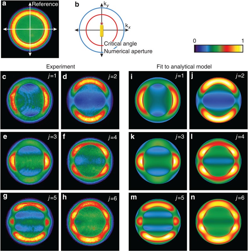
Polarization alone, however, does not allow identification of the resonance order or multipolar character of the emission. For a detailed understanding of resonant antenna modes and their coupling to QDs, we turn to angular radiation patterns24,33 for selected QD–antenna systems, which will ultimately lead us to a quantitative demonstration of multipolar radiation. The antennas lie on a glass substrate that affects the angular radiation patterns by funnelling and projecting most of the emission into the substrate half-space, especially above the critical angle of the air–glass interface. As a result, the radiation pattern of a point multipole on a substrate (Fig. 1c) differs from what is expected in free space (Supplementary Fig. S1). Fourier images of single antennas contain the directions of emission of the coupled system into the substrate. For off-resonance lengths, similar to the absence of polarization, the QD angular emission is hardly affected by the antenna and the pattern is rotationally symmetric (Fig. 3a and Supplementary Fig. S2). At resonance, the angular pattern becomes dominated by the antenna mode. For the j=1 resonance, the emission represents a linear dipole along the antenna (Fig. 3c); the degeneracy in transition dipole moment of our QDs (Fig. 3a) is lifted by coupling to the antenna mode6. The j=2 resonance has even charge symmetry and its radiation pattern is oriented perpendicular to the first mode (Fig. 3d and Supplementary Fig. S3), corresponding to a linear quadrupole. Owing to their opposite symmetry and despite their parallel polarization along the antenna, the central horizontal maximum in the emission of the dipole becomes a minimum in the emission of the quadrupole. The third order resonance has the symmetry of the half-wave dipole antenna but the lobes are now narrower (Fig. 3e), a characteristic of higher multipoles. For increasing order modes, additional lobes appear, with alternating symmetry and positions of minima and maxima. The patterns gradually wash out for higher-order resonances due to a lower coupling resulting in a rotationally symmetric background (pure antenna modes shown in Supplementary Fig. S4). For longer wires7,9,25, several resonances start overlapping within the QD luminescence spectrum, and a band pass filter was used to select the central part of the emission spectrum for j=5 and j=6 to improve the contrast (Fig. 3g).
Figure 3. Multipolar angular radiation patterns of quantum dots coupled to antennas of increasing resonance order.
Fourier-space patterns recorded in the back focal plane of the microscope objective. (a) Reference structure: QD on an off-resonance 60-nm square. (b) Schematic of an angular pattern highlighting the critical angle of the glass–air interface and the numerical aperture of the objective (maximum collection angle). Antenna orientation and relative QD position are superimposed. (c–h) Experimental patterns of the first six resonant antenna modes. The first four antennas are the individual antennas marked in Fig. 2b. The colour scale represents normalized counts. (i–n) The patterns are reproduced with the analytical resonator model, including a rotationally symmetric background. The left and right columns group together odd and even modes, respectively, with opposite angular symmetries.
The j=2 resonance illustrates the physics involved. This antenna efficiently converts the emission of a dipolar transition (QD) into quadrupolar radiation by coupling to the optical antenna. Its angular pattern consists of two broad lobes directed along the antenna and resembles the pattern of a point quadrupole on glass (Fig. 1d). The coupling of a dipole transition to a quadrupolar mode is possible because the placement of the QD at the end of the antenna breaks the inversion symmetry of the QD–antenna system. As the total antenna length (260 nm) is on the order of half the wavelength, the j=2 mode radiates effectively24. It is therefore neither sub-radiant nor dark, despite its even charge symmetry. For antennas, multipolar moments are not necessarily small and, for antenna dimensions on the order of the wavelength, the radiant character of the mode is independent of its multipolar nature. Multipolar and dipolar antenna modes radiate with a comparable rate, in contrast to multipolar transitions in small quantum emitters such as molecules, QDs or ions, which are usually several orders of magnitude slower in radiative rates than dipolar transitions. Indeed, the ratios of average detected luminescence for the different modes are Ij=1:Ij=2:Ij=3:Ij=4=1:0.4:0.25:0.3 with oscillations in radiated power following those of the polarization response (Supplementary Fig. S5). In absolute terms, the average count rate for the dipolar resonance (Ij=1) is 135 kCounts per ms for an excitation power density of 1.08 kW cm−2. A QD coupled to the j=2 mode thus provides a novel nanoscale system: a bright single quantum emitter that interacts with light as a quadrupole.
To assess the strength of the coupling of the QDs to the antennas, we compare the experimental angular patterns to our one-dimensional analytical model in Fig. 3i–n. The experimental results fit accurately to a sum of the theoretical antenna emission pattern, that is, pure antenna mode, plus an incoherent background consisting of two equal in-plane dipoles. The relative weights of the antenna mode and the uncoupled background give a measure for the effectiveness of the coupling of the QD to the antenna mode. We find that the fraction of the emitted power corresponding to the antenna mode is 90 and 60% for the first two resonances j=1 and j=2, respectively, denoting high coupling efficiencies between the QD and the plasmon mode of the antenna. The coupling is stronger than for longer nanowires8,9 due to enhancement by the antenna resonances.
Multipolar expansion
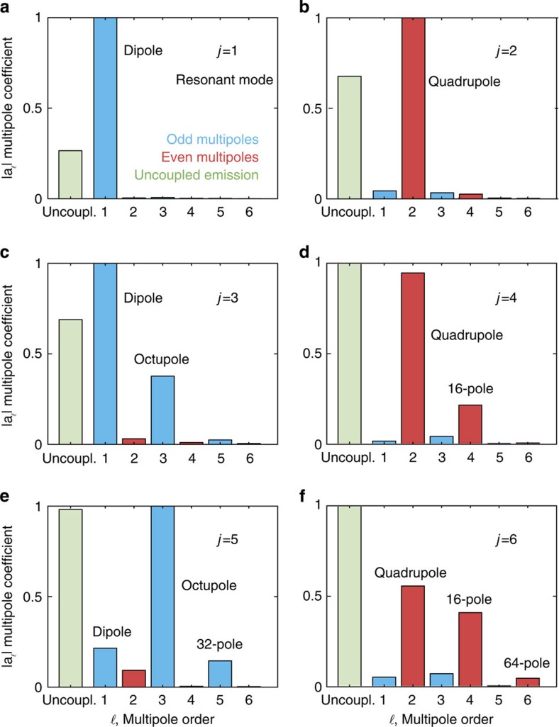
To describe the nature of these radiating modes, we reproduce their angular patterns with a point multipolar expansion34, conclusively demonstrating multipolar radiation of otherwise dipolar quantum emitters. An oscillating distribution of charge on a wire generates propagating electromagnetic fields that can be decomposed in axial multipoles oriented along the antenna. As magnetic multipoles vanish for line sources, we fit our experimental results of individual antennas with a coherent superposition of electric multipoles (ℓ) near a dielectric interface (Fig. 4). We add again an incoherent background of two in-plane dipoles, with emission constant in the azimuth angle like an uncoupled QD. The expansion coefficients (aℓ) for the first two resonant modes confirm our previous assignments of their prominently dipolar and quadrupolar characters and the efficient coupling to both antennas. Although it is tempting to assign one multipole order to each resonant mode, for instance ℓ=3 multipole to j=3 mode, this is generally not the case. For higher-order resonances, even modes are composed of a coherent superposition of predominantly even multipoles; complementarily, odd modes are dominated by odd multipoles.
Figure 4. The multipolar nature of the emission is described by a multipolar expansion of the angular radiation patterns.
(a–f) The experimental radiation patterns of the individual resonant antennas of Fig. 3c–h were fit to a superposition of even (red) and odd (blue) multipoles oriented along the antenna plus an incoherent rotationally symmetric background consisting of two in-plane dipoles (uncoupled emission, green). Superpositions of even and odd multipoles dominate the even (right) and odd (left) modes, respectively. The complex multipole coefficients |aℓ| are normalized to the amplitude of the maximum coefficient. Note that for equal coefficient amplitudes |aℓ|, each isolated term in the expansion radiates the same power in free space.
Discussion
In a broader context of plasmonic modes, angular measurements are a powerful tool for understanding how the unit cells of metamaterials interact with light35,36,37,38. In metamaterials, the near-field coupling between elements supporting different modes, for example, dipole-quadrupole, leads to interesting polarization39 and spectral effects such as electromagnetically induced transparency40,41, a situation that resembles the coupling of dipolar QDs to quadrupolar antennas. Similar effects could therefore be explored in the hybrid systems explored here, formed by the combination of quantum-mechanical transitions and plasmon modes. On the other hand, the multipolar character of an emitter is intimately related to the angular momentum of light42,43,44,45. In addition to the angular intensity distributions, the antenna also controls the phase behind each lobe. Hence, the ideas presented here can be extended to design systems that could serve as nanoscale sources and detectors of optical angular momentum. Furthermore, a multipole moment is mostly sensitive to certain components of the electromagnetic field46. With a QD coupled to the quadrupolar mode, for example, a nanoscale probe that is sensitive to the electric field gradient can be envisioned.
In conclusion, we presented a systematic study of nanowire modes and their interaction with quantum emitters. The use of optical antennas allowed us to convert the radiation of electric dipole transitions efficiently into novel multipolar sources of photons. Our results provide a wealth of new opportunities for the nanoscale control and engineering of the interaction of single quantum emitters with well-defined modes of the light field. Finally, we anticipate that optical antennas could also be devised to favour a given quantum-mechanical multipolar transition in the emitter itself, bringing into light forbidden transitions47,48,49.
Methods
Positioning of QDs
We employ commercially available QDs (Invitrogen, Qdot 800 ITK amino (PEG)), which are core/shell (CdSeTe/ZnS) nanocrystals with a polymer coating. A first lithography defines the gold antennas (width 60 nm, height 30 nm) and alignment markers. A second lithographic layer opens gaps on the areas that will be functionalized for QD attachment. Chemical specificity to gold is provided by a mercaptoundecanoic acid monolayer only on the predefined areas, where the QDs are selectively attached.
Polarization measurements
The QD luminescence was collected by a scanning confocal microscope and split by a calibrated polarizing beamsplitter onto two avalanche photodiodes to calculate the DOLP. The QDs were excited at 633 nm with an incident circularly polarized beam of a few microwatts of power, and the excitation and emission were separated by a dichroic mirror (Semrock, FF665-Di02) and a long-pass filter (Omega Optical, 690ALP). The emission spectra of QDs with and without antennas can be found in Supplementary Fig. S6, which are compared with dark-field scattering spectra of the antennas in Supplementary Fig. S7.
Angular measurements
The angular luminescence emission of individual antennas was directly recorded by imaging the back focal plane of an oil-immersion high numerical aperture objective (Zeiss α Plan-Apochromat × 100, 1.46) onto an electron-multiplying CCD camera (Andor, iXon+897). This plane contains the Fourier-space image of the object plane. Antennas on a substrate were excited and recorded one at a time with a focused beam. The maxima of counts per pixel for the normalized images of the antennas in Fig. 3c–h are 53.9 (j=1), 54.5 (j=2), 42.4 (j=3), 30.7 (j=4), 27.6 (j=5) and 16.8 (j=6) kCounts, accumulated over a total exposure time of 90 s.
One-dimensional cavity model
A nanowire can be parameterized with the following values24: the wavelength of the plasmon propagating along the wire λSP, related for a given mode to the effective refractive index; the losses on propagation Im(k); the reflectivity at the ends of the wire r; and the phase picked up on reflection φ. These parameters are retrieved by fitting to the experiment in polarization and angular measurements, adding background contributions of radiation not coupled to the antenna mode. Resonances are found for lengths that satisfy the condition ℓn=λSP/2 (n−φ/π), where n is a positive integer. For an electric dipole at one of the ends of the antenna (position y=−ℓ/2), the current distribution along the antenna is given by:
 |
From this current distribution we obtain the emitted field as:
 |
in which kx and ky are the projections of the wave vector (magnitude k0) of the emitted radiation along x and y, and E0(kx, ky) is the electric field emitted by a y-oriented electric dipole above an air–glass interface. This dipole is situated 15 nm away from the interface on the air side, at half the antenna height of 30 nm in the experiment.
Equation 2 directly yields the back focal plane image for the antenna mode:
 |
in which η is the impedance of the medium.
This model describes the emission of the antenna mode alone, regardless of the number of emitters coupled to it. An additional background term of in-plane dipoles was added to take into account uncoupled radiation (uncoupled QD emission and antenna autoluminescence) that does not carry the characteristic antenna emission pattern. The background is taken as incoherent, as a good approximation, because of the broad spectrum and the random polarization of the QDs, and the incoherent nature of metal luminescence. Moreover, the differences in emission between uncoupled QDs and antenna modes, each under specific angles, polarizations and phases, reduce the visibility of interference even further.
For the analysis of polarization measurements, the average DOLP can be described by:
 |
where Ix and Iy are counts that would be detected through a linear polarizer along x or y, respectively. The constants α and β are the relative weights of the two background polarizations with respect to the antenna mode, found by fitting to the experimental data.
For the analysis of angular patterns, the back focal plane image  of each individual antenna was reproduced with the equation:
 |
where the optimal weights (A and B) of the antenna mode ( , given by equation 3) and the uncoupled background (
 and
and  ) were found by fitting to the experimental data.
For further details on this model and the fitting of polarization and angular measurements, including fitting results, see Supplementary Note 1, Supplementary Figs S3 and S8, and Supplementary Tables S1 and S2.
Multipolar expansion of angular patterns
The angular patterns of electric multipoles near a dielectric interface are calculated using the angular spectrum representation based on vector spherical harmonics34. Both propagating and evanescent fields are refracted and reflected using the Fresnel coefficients of the air–glass interface. The experimental angular patterns are reproduced with a coherent superposition of electric multipoles with complex coefficients aℓ and field components Eℓx,y,z(kx,ky). Only longitudinal electric multipoles oriented along the antenna are required due to the one-dimensional character of our antennas. We added two incoherent perpendicular dipoles ( and
and  ) to account for uncoupled emission originating from antenna luminescence and from uncoupled QD luminescence, which empirically describes our rotationally symmetric background in angular patterns. The total angular pattern is thus:
 |
Only six terms in the multipolar expansion (1<ℓ<6) were necessary for a robust fit in order to find the complex coefficients  , and the real coefficient b. The fields radiated by every multipole and the two background contributions
  and
and 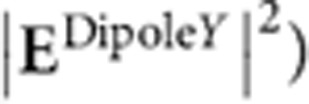 were normalized, so that equal coefficients
  and b radiated the same power in free space. On the substrate, the radiated powers integrated over all directions are 1.29, 2.58, 2.70 and 7.75 times the free-space power for the dipole ℓ=1, the uncoupled background dipoles, the quadrupole ℓ=2, and the octupole ℓ=3, respectively. The quality of the results of fitting the angular measurements with this multipolar expansion is analysed in Supplementary Figs S9 and S10, and in Supplementary Table S3.
Author contributions
A.G.C., T.H.T., G.V. and N.F.v.H. conceived the experiment; G.V. and M.P.K. fabricated the sample and positioned the QDs; A.G.C. performed the measurements, analysed the data, implemented the multipolar expansion and wrote the manuscript; T.H.T. developed the analytical one-dimensional model; R.Q. and N.F.v.H. supervised the project. All authors discussed the results and commented on the final manuscript.
Additional information
How to cite this article: Curto, A. G. et al. Multipolar radiation of quantum emitters with nanowire optical antennas. Nat. Commun. 4:1750 doi: 10.1038/ncomms2769 (2013).
Supplementary Material
Supplementary Figures S1-S10, Supplementary Tables S1-S3, Supplementary Note 1 and Supplementary References
Acknowledgments
We thank Richard Hildner, Marta Castro-López, Martin Kuttge and Daan Brinks for technical help and stimulating discussions. This work was financially supported by the Spanish Ministry of Science and Innovation (MICINN) and Ministry of Education through programs FIS2009-08203, CONSOLIDER CSD2007-046, FPU (A.G.C. and G.V.), FPI (T.H.T.) and Ramón y Cajal (M.P.K.), Fundació CELLEX Barcelona (R.Q., N.F.v.H.) and the European Research Council (R.Q., ERC-StartGrant; N.F.v.H., ERC-AdvGrant).
References
- Novotny L. & van Hulst N. F. Antennas for light. Nat. Photon. 5, 83–90 (2011) . [Google Scholar]
- Biagioni P., Huang J.-S. & Hecht B. Nanoantennas for visible and infrared radiation. Rep. Prog. Phys. 75, 024402 (2012) . [DOI] [PubMed] [Google Scholar]
- Kühn S., Hakanson U., Rogobete L. & Sandoghdar V. Enhancement of single-molecule fluorescence using a gold nanoparticle as an optical nanoantenna. Phys. Rev. Lett. 97, 017402 (2006) . [DOI] [PubMed] [Google Scholar]
- Kinkhabwala A. et al. Large single-molecule fluorescence enhancements produced by a bowtie nanoantenna. Nat. Photon. 3, 654–657 (2009) . [Google Scholar]
- Schietinger S., Barth M., Aichele T. & Benson O. Plasmon-enhanced single photon emission from a nanoassembled metal−diamond hybrid structure at room temperature. Nano Lett. 9, 1694–1698 (2009) . [DOI] [PubMed] [Google Scholar]
- Curto A. G. et al. Unidirectional emission of a quantum dot coupled to a nanoantenna. Science 329, 930–933 (2010) . [DOI] [PubMed] [Google Scholar]
- Ditlbacher H. et al. Silver nanowires as surface plasmon resonators. Phys. Rev. Lett. 95, 257403 (2005) . [DOI] [PubMed] [Google Scholar]
- Akimov A. V. et al. Generation of single optical plasmons in metallic nanowires coupled to quantum dots. Nature 450, 402–406 (2007) . [DOI] [PubMed] [Google Scholar]
- Kolesov R. et al. Wave-particle duality of single surface plasmon polaritons. Nat. Phys. 5, 470–474 (2009) . [Google Scholar]
- Huang K. C. Y. et al. Antenna electrodes for controlling electroluminescence. Nat. Commun. 3, 1005 (2012) . [DOI] [PubMed] [Google Scholar]
- Imura K., Nagahara T. & Okamoto H. Plasmon mode imaging of single gold nanorods. J. Am. Chem. Soc. 126, 12730–12731 (2004) . [DOI] [PubMed] [Google Scholar]
- Dorfmüller J. et al. Fabry-Pérot resonances in one-dimensional plasmonic nanostructures. Nano Lett. 9, 2372–2377 (2009) . [DOI] [PubMed] [Google Scholar]
- Esteban R. et al. Direct near-field optical imaging of higher order plasmonic resonances. Nano Lett. 8, 3155–3159 (2008) . [DOI] [PubMed] [Google Scholar]
- Schnell M. et al. Controlling the near-field oscillations of loaded plasmonic nanoantennas. Nat. Photon. 3, 287–291 (2009) . [Google Scholar]
- Fumeaux C. et al. Measurement of the resonant lengths of infrared dipole antennas. Infrared Phys. Technol. 41, 271–281 (2000) . [Google Scholar]
- Barnard E. S., Pala R. A. & Brongersma M. L. Photocurrent mapping of near-field optical antenna resonances. Nat. Nanotech. 6, 588–593 (2011) . [DOI] [PubMed] [Google Scholar]
- Vesseur E. J. R., de Waele R., Kuttge M. & Polman A. Direct observation of plasmonic modes in au nanowires using high-resolution cathodoluminescence spectroscopy. Nano Lett. 7, 2843–2846 (2007) . [DOI] [PubMed] [Google Scholar]
- Coenen T., Vesseur E. J. R. & Polman A. Deep subwavelength spatial characterization of angular emission from single-crystal au plasmonic ridge nanoantennas. ACS Nano 6, 1742–1750 (2012) . [DOI] [PubMed] [Google Scholar]
- Douillard L. et al. Short range plasmon resonators probed by photoemission electron microscopy. Nano Lett. 8, 935–940 (2008) . [DOI] [PubMed] [Google Scholar]
- Nelayah J. et al. Mapping surface plasmons on a single metallic nanoparticle. Nat. Phys. 3, 348–353 (2007) . [Google Scholar]
- Aizpurua J. et al. Optical properties of coupled metallic nanorods for field-enhanced spectroscopy. Phys. Rev. B 71, 235420 (2005) . [Google Scholar]
- Novotny L. Effective wavelength scaling for optical antennas. Phys. Rev. Lett. 98, 266802 (2007) . [DOI] [PubMed] [Google Scholar]
- Barnard E. S., White J. S., Chandran A. & Brongersma M. L. Spectral properties of plasmonic resonator antennas. Opt. Express 16, 16529–16537 (2008) . [DOI] [PubMed] [Google Scholar]
- Taminiau T. H., Stefani F. D. & van Hulst N. F. Optical nanorod antennas modeled as cavities for dipolar emitters: evolution of sub- and super-radiant modes. Nano Lett. 11, 1020–1024 (2011) . [DOI] [PubMed] [Google Scholar]
- Della Valle G., Sondergaard T. & Bozhevolnyi S. I. Plasmon-polariton nano-strip resonators: from visible to infra-red. Opt. Express 16, 6867–6876 (2008) . [DOI] [PubMed] [Google Scholar]
- Kajetan Schmidt M., Mackowski S. & Aizpurua J. Control of single emitter radiation by polarization- and position-dependent activation of dark antenna modes. Opt. Lett. 37, 1017–1019 (2012) . [DOI] [PubMed] [Google Scholar]
- Michler P. et al. Quantum correlation among photons from a single quantum dot at room temperature. Nature 406, 968–970 (2000) . [DOI] [PubMed] [Google Scholar]
- Messin G., Hermier J. P., Giacobino E., Desbiolles P. & Dahan M. Bunching and antibunching in the fluorescence of semiconductor nanocrystals. Opt. Lett. 26, 1891–1893 (2001) . [DOI] [PubMed] [Google Scholar]
- Lounis B., Bechtel H. A., Gerion D., Alivisatos P. & Moerner W. E. Photon antibunching in single CdSe/ZnS quantum dot fluorescence. Chem. Phys. Lett. 329, 399–404 (2000) . [Google Scholar]
- Mertens H., Biteen J. S., Atwater H. A. & Polman A. Polarization-selective plasmon-enhanced silicon quantum-dot luminescence. Nano Lett. 6, 2622–2625 (2006) . [DOI] [PubMed] [Google Scholar]
- Koberling F. et al. Fluorescence anisotropy and crystal structure of individual semiconductor nanocrystals. J. Phys. Chem. B 107, 7463–7471 (2003) . [Google Scholar]
- Empedocles S. A., Neuhauser R. & Bawendi M. G. Three-dimensional orientation measurements of symmetric single chromophores using polarization microscopy. Nature 399, 126–130 (1999) . [Google Scholar]
- Encina E. R. & Coronado E. A. Plasmonic nanoantennas: angular scattering properties of multipole resonances in noble metal nanorods. J. Phys. Chem. C 112, 9586–9594 (2008) . [Google Scholar]
- Inoue T. & Hori H. Theoretical treatment of electric and magnetic multipole radiation near a planar dielectric surface based on angular spectrum representation of vector field. Opt. Rev. 5, 295–302 (1998) . [Google Scholar]
- Sersic I., Tuambilangana C. & Koenderink A. F. Fourier microscopy of single plasmonic scatterers. New J. Phys. 13, 083025 (2011) . [Google Scholar]
- Mühlig S., Menzel C., Rockstuhl C. & Lederer F. Multipole analysis of meta-atoms. Metamaterials 5, 64–73 (2011) . [Google Scholar]
- Cho D. J., Wang F., Zhang X. & Shen Y. R. Contribution of the electric quadrupole resonance in optical metamaterials. Phys. Rev. B 78, 121101 (2008) . [Google Scholar]
- Grahn P., Shevchenko A. & Kaivola M. Electromagnetic multipole theory for optical nanomaterials. New J. Phys. 14, 093033 (2012) . [Google Scholar]
- Tate N. et al. Quadrupole-dipole transform based on optical near-field interactions in engineered nanostructures. Opt. Express 17, 11113–11121 (2009) . [DOI] [PubMed] [Google Scholar]
- Liu N. et al. Plasmonic analogue of electromagnetically induced transparency at the Drude damping limit. Nat. Mater. 8, 758–762 (2009) . [DOI] [PubMed] [Google Scholar]
- Zhang S., Genov D. A., Wang Y., Liu M. & Zhang X. Plasmon-induced transparency in metamaterials. Phys. Rev. Lett. 101, 047401 (2008) . [DOI] [PubMed] [Google Scholar]
- Jackson J. D. Classical Electrodynamics Wiley (1999) . [Google Scholar]
- Foreman M. R. & Török P. Spin-orbit coupling and conservation of angular momentum flux in non-paraxial imaging of forbidden radiation. New J. Phys. 13, 063041 (2011) . [Google Scholar]
- Molina-Terriza G. Determination of the total angular momentum of a paraxial beam. Phys. Rev. A 78, 053819 (2008) . [Google Scholar]
- Andrews D. L. Optical angular momentum: multipole transitions and photonics. Phys. Rev. A 81, 033825 (2010) . [Google Scholar]
- Burresi M. et al. Probing the magnetic field of light at optical frequencies. Science 326, 550–553 (2009) . [DOI] [PubMed] [Google Scholar]
- Karaveli S. & Zia R. Spectral tuning by selective enhancement of electric and magnetic dipole emission. Phys. Rev. Lett. 106, 193004 (2011) . [DOI] [PubMed] [Google Scholar]
- Yang N. & Cohen A. E. Local geometry of electromagnetic fields and its role in molecular multipole transitions. J. Phys. Chem. B 115, 5304–5311 (2011) . [DOI] [PubMed] [Google Scholar]
- Andersen M. L., Stobbe S., Sørensen A. S. & Lodahl P. Strongly modified plasmon-matter interaction with mesoscopic quantum emitters. Nat. Phys. 7, 215–218 (2011) . [Google Scholar]
Associated Data
This section collects any data citations, data availability statements, or supplementary materials included in this article.
Supplementary Materials
Supplementary Figures S1-S10, Supplementary Tables S1-S3, Supplementary Note 1 and Supplementary References


