Abstract
In parallel excitation, the computational speed of numerical radiofrequency (RF) pulse design methods is critical when subject dependencies and system nonidealities need to be incorporated on-the-fly. One important concern with optimization-based methods is high peak RF power exceeding hardware or safety limits. Hence, online controllability of the peak RF power is essential. Variable-rate selective excitation pulse reshaping is ideally suited to this problem due to its simplicity and low computational cost. In this work, we first improve the fidelity of variable-rate selective excitation implementation for discrete-time waveforms through waveform oversampling such that variable-rate selective excitation can be robustly applied to numerically designed RF pulses. Then, a variable-rate selective excitation-guided numerical RF pulse design is suggested as an online RF pulse design framework, aiming to simultaneously control peak RF power and compensate for off-resonance.
Keywords: VERSE, RF excitation, numerical RF pulse design, peak RF power, multidimensional, parallel
In magnetic resonance imaging (MRI), selectivity in the spectral and/or spatial dimensions is achieved by simultaneously controlling radiofrequency (RF) and gradient waveforms. Typically, a k-space trajectory (1) is first determined by the excitation characteristics such as the field-of-excitation (FOX) and the sharpness of transition bands. Gradient waveforms G(t) = [Gx (t), Gy (t), Gz (t)]T are then designed to generate the trajectory while satisfying hardware limitations and imaging requirements. Finally, complex-valued RF waveforms, B1(t) = B1,x (t) + iB1,y (t), are calculated to achieve the target excitation profile.
Numerical optimization-based RF pulse design methods have gained considerable attention due to recent interest in parallel transmission (2–8). A significant benefit of numerical approaches over closed form solutions is their ability to compensate for transmit field inhomogeneity, off-resonance, and signal decay, and to incorporate RF power limits and regions-of-interest. However, these approaches often produce pulses with high peak RF magnitudes exceeding hardware or safety limits (5,7,9). This requires careful user adjustment of pulse parameters to balance peak RF magnitude with time efficiency and susceptibility to off-resonance, motion, and signal decay effects (10). As the computational speed of parallel RF pulse design is critical, direct peak-RF-power constraint approaches (11) are unattractive because the associated computational cost is too high to be practical. When a peak-RF-power constraint is directly embedded in a numerical RF pulse design, it needs to solve an inequality-constrained minimization problem, which takes much more time as it solves a large sequence of unconstrained problems. Moreover, when the hard peak-RF-power constraint is enforced on fixed gradient waveforms, the solution space of RF waveforms shrinks, resulting in an inferior excitation quality over a narrow range of peak RF suppression.
In contrast, the variable-rate selective excitation (VERSE) technique (10,12–19) can limit the peak RF power in a fast and robust way by solving a much simpler gradient design problem rather than a RF design problem with a peak-RF-power constraint (19). The VERSE technique minimizes the amount of reshaping via a local-only RF and gradient scaling while maintaining the on-resonance profile. The utility of numerically designed RF pulses would be enhanced by the VERSE-based online peak-RF-power controllability. However, VERSE reshaping does not take off-resonance into account, leading to excitation errors. Also, the discrete-time and high-bandwidth nature of numerically designed RF pulses makes it more difficult to maintain the VERSE condition, requiring careful VERSE implementation.
This article complements our previous work on multidimensional and parallel transmit VERSE (19) by addressing the above-mentioned practical challenges. We first discuss how to improve the fidelity of VERSE reshaping for discrete-time waveforms such that VERSE can be robustly applied to numerically designed RF pulses. Then, a VERSE-guided numerical RF pulse design is introduced as an online RF pulse design framework, aiming to control peak RF power and compensate for off-resonance at the same time.
THEORY
Peak RF Control by VERSE Principle
According to the VERSE principle, the rotational behavior of on-resonance spins is completely determined by the evolution of the RF-to-gradient amplitude ratio in excitation k space. Thus, spin rotation can be preserved simply by maintaining this ratio, while traversing the identical excitation k-space trajectory.
The VERSE principle was generalized to the one-dimensional Euclidean arc-length domain in our previous work (19), where the arc-length s describes points along RF and gradient waveforms as a function of total distance traversed in excitation k space:
| [1] |
Assuming the same excitation k-space trajectory as the original waveform pair {B1(s), G(s)}, the VERSE condition for the VERSE’d waveform pair { , Gv (s)} is summarized by an invariant RF-to-gradient amplitude ratio, W (s),
| [2] |
through which a peak-RF-power constraint becomes equivalent to a gradient-amplitude constraint:
| [3] |
When combined with the maximum gradient amplitude constraint, VERSE gradients must satisfy
| [4] |
at any s to keep the VERSE pulse within the hardware limits, B1,max and Gmax. Based on this relationship, we can control the peak RF power by solving a simpler gradient design problem (19,20).
Discrete-Time VERSE
As the VERSE principle is a relationship among continuous waveforms, an extension of VERSE technique to discrete-time waveforms involves additional digital-to-analog (D/A) conversion. An original discrete-time pair, {B1[n], G[n]}, is first converted to a continuous-time {B1(t), G(t)}, and this determines the expected excitation and W (s). The gradient waveform is reshaped to Gv (t) to meet the gradient and RF constraints, and the corresponding RF waveform, , is determined according to Eq. 2. Finally, the resultant waveforms are sampled for the MR hardware, { , Gv [n]}.
In general, simplified models such as Dirac-δ and zero-order-hold signal models are used in most numerical RF designs. These assume that the impact of system responses is negligible on the excitation profile inside the FOX. However, the zero-order-hold interpolation is not a suitable D/A method for VERSE even for those pulses designed using Dirac-δ or zero-order-hold models as it introduces discontinuities in W (s) that cannot be realized in VERSE’d waveforms due to the bandwidth limits of the hardware. In this regard, smooth interpolation methods are desirable for the purpose of achieving realizable W (s). Here, spline interpolation was chosen to avoid oscillatory behavior in waveforms. Also, it guarantees the exact RF-to-gradient amplitude ratio for the original sampling points.
When the VERSE technique is implemented on a computer, continuous waveforms are also approximated by digital samples. To achieve better registration of the RF-to-gradient amplitude ratio in the s domain, the arc-length calculation, approximated by numerical integration, needs to be accurate. Thus, it requires a shorter sampling time of the digital samples than the hardware update time in RF design. This is especially important for numerically designed RF pulses as high-bandwidth RF pulses need to be accurately registered to the reshaped gradients whose bandwidth is higher than the original waveforms. Likewise, VERSE’d gradient waveforms need to be designed with a short enough update time to track the nominal k-space trajectory, which is a critical VERSE condition.
reVERSE: RF Redesign with VERSE Precompensation
One drawback to VERSE reshaping is that it ignores off-resonance and T2-decay effects that affect the rotational behavior of spins depending on how the pulse is reshaped (12). From an s-domain perspective, off-resonance locally distorts the incremental rotation by effectively modifying the local gradient amplitude, which can be readily understood by adding off-resonance effects to the term “g(s) · r” in Eq. 5 of Ref. 19,
| [5] |
where φ′(s, r) and n(s, r) are the incremental spin rotation and its axis, respectively.
As we start with numerical RF design, which takes , ΔB0, and other design parameters as inputs, one simple way to compensate for this off-resonance disturbance is to reapply the same RF design method to the VERSE’d gradient waveforms, a process that will be referred to as reVERSE. The redesign process quickly finds the local optimal solution because the VERSE’d RF design is already a very good initial solution. In doing so, not only are the field inhomogeneity taken into account but also residual errors from the discrete-time VERSE are corrected.
However, it is possible that a reVERSE pulse converges to significantly different peak RF power due to the RF waveform’s dependence on factors such as off-resonance distribution, the degree of peak-RF-power suppression, and RF power penalization. To resolve this issue, an iterative approach can be adopted to gradually reduce the deviation of peak RF magnitude of reVERSE pulse from the target value as summarized in Table 1. Basically, the deviation of peak RF magnitude from B1,max becomes smaller by reVERSE and this reduced deviation of the current iteration makes the amount of reshaping smaller in the subsequent iteration. Thus, peak RF magnitude converges to B1,max as the algorithm progresses.
Table 1.
Outline of the Iterative reVERSE Algorithm
| Inputs: |
| rfd(·): RF design function, returning an RF pulse |
| B1,max: peak-RF-magnitude target |
| Gmax: maximum gradient amplitude |
| α: attenuation factor of B1,max for the use in VERSE, e.g., α = 0.9 |
| T: hardware update time |
| : transmit RF field |
| ΔB0(r): main-field inhomogeneity |
| Outputs: |
| B1[n], G[n]: reVERSE pulse waveforms
|
Algorithm:
|
It is important to realize that, in theory, the arc-length must be calculated in the continuous-time domain to improve registration accuracy while its numerical implementation approximates it with a much shorter sampling time than the hardware update time. Though we assumed a longer sampling time of RF waveforms for faster RF designs, we can avoid the discretization error by designing intermediate RF waveforms in the continuous-time domain. Then, the interpolation in Step 4a of Table 1 is not necessary, and only the final waveforms need to be discretized with the hardware update time. Also, note that the peak-RF-magnitude target in VERSE is set lower than the nominal target (i.e., αB1,max, α < 1). If we use the same nominal target for the VERSE step, it may cost extra iterations only to correct little overshoots from the pulse redesign, which has little practical importance. Also, when the deviation is very little, it is even possible that the reVERSE would increase the peak RF value, leading to an oscillatory behavior in its peak RF magnitude through iterations. Thus, this attenuated target value improves the convergence speed and stability of the algorithm.
MATERIALS AND METHODS
The Dirac-δ behavior is assumed in both RF pulse designs and Bloch simulations, i.e., spin rotation (including the phase evolution by off-resonance) occurs only at discrete sampling times. We used the cubic-spline interpolation method for interpolating curves and numerical integrations were approximated by the trapezoidal rule.
RF Pulse Design
The fast large-tip-angle method in Ref. 21 was used to design 2-D parallel excitation RF pulses. This is a fast version of the optimal control method that is formulated as alternations between Bloch simulation and perturbation-pulse design. Each pulse update is accelerated by the linearization of the Bloch equations, being searched by stepping in the negative gradient direction of a quadratic cost function, Ψ of Eq. 25 in Ref. 21. In each perturbation pulse design, 32 conjugate gradient iterations were executed. The pulse design alternations were terminated when the normalized root-mean-square error (NRMSE) at the current alternation decreased by less than 0.01% of the previous one. We defined NRMSE as the error between the desired pattern and the Bloch-simulated magnetization pattern as in the Eq. 37 of Ref. 21. For dual-band excitations, this method was extended to target both water and fat frequencies by concatenating magnetization vectors and system matrices within the cost function (22,23). The current implementation allows a constant phase shift over the fat profile relative to the water profile, which is jointly optimized with the RF to improve pulse realizability.
All RF pulses are normalized to the maximum digital input of the transmit channel and each map corresponds to this full scale RF input. Thus, the actual RF waveform at spatial location r is given by
| [6] |
where B1,n(t) and dn(r) are normalized RF waveform and map for channel n, respectively, and N is the number of transmit channels.
Numerical Simulations
Eight channel accelerated 2-D parallel excitation RF pulses were designed with echo-planar (EP) excitation k-space trajectories, assuming a maximum gradient amplitude (Gmax) of 40 mT/m (except dual-band 2-D spatial excitations) and a maximum gradient slew rate (Smax) of 150 T/m/s. EP trajectories were chosen as they are very sensitive to timing errors, which is well suited for validating the numerical accuracy of VERSE implementation. Gradients were time-optimally designed assuming arbitrary rotation angles. We used modeled transmit sensitivity ( ) patterns for eight channels in Fig. 1a (24,25). All excitation pulses targeted a spatial resolution of 0.75 cm and FOX of 9 cm. As shown in Fig. 1c, a 10 × 5 cm2 rectangular target profile providing π/2 flip angle was blurred via convolution with a Gaussian kernel of 1.2 cm full-width-at-half-maximum; we aimed to cancel out the aliased excitations at y = ±9 cm with parallel transmit. All spatial-domain information was specified on the same 64 × 64 Cartesian grid in a 24 × 24 cm2 region-of-interest.
FIG. 1.
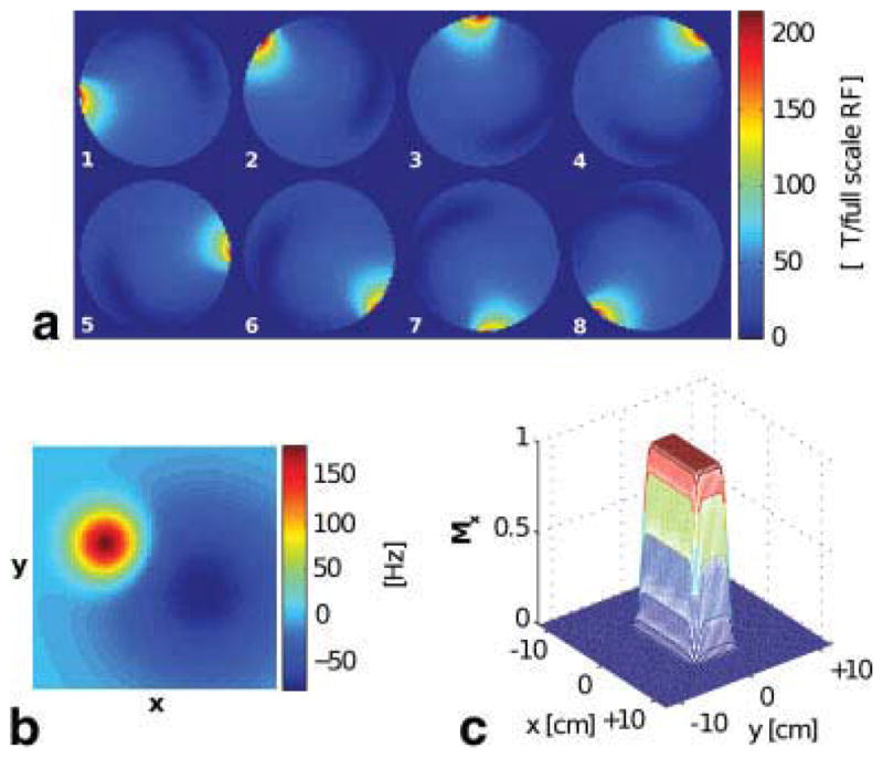
All spatial-domain information for 2-D spatial excitation was specified on a 64 × 64 Cartesian grid in a 24 × 24 cm2 region-of-interest as follows: a: transmit-sensitivity patterns of an eight-channel system (only the magnitude part is displayed), b: off-resonance map, and c: desired excitation pattern. [Color figure can be viewed in the online issue, which is available at wileyonlinelibrary.com.]
The accuracy of the VERSE reshaping was validated with 2-D spatial excitation pulses by comparing various waveform-oversampling factors and gradient-design sampling times. For simulations, all VERSE’d waveforms were resampled with a sampling time of 4 μs. The impact of reshaping was studied by comparing moderate peak-RF-power suppression examples to the examples without reshaping (i.e., B1,max = ∞) by setting B1,max lower than the initial peak RF magnitude. Then, the same simulations were repeated for the RF pulse designs with spatially varying off-resonance ( ) in Fig. 1b. Finally, dual-band 2-D spatial excitations were simulated assuming a homogeneous 1.5 T main magnetic field (B0(r) = 1.5 T), where excitation profiles were optimized at both water (0 Hz) and fat (−220 Hz) frequencies. While different maximum gradient amplitude constraints were employed in their initial gradient designs, Gmax = 40 mT/m was used for VERSE and reVERSE operations. When the peak RF magnitude of a reVERSE pulse deviates from B1,max, we switched to the iterative reVERSE framework with the B1,max-attenuation factor α = 0.9, ensuring a faster decrease in peak RF magnitude throughout the iterations.
Scanner Experiments
We performed 2-D spatial parallel excitation experiments on a GE Signa 1.5 T scanner (GE Healthcare, Milwaukee, WI) with Gmax = 40 mT/m, Smax = 150 T/m/s, and a receiver sampling bandwidth of ±125 kHz. The relative timing of RF to gradient was adjusted with a half-sample precision (i.e., 2 μs) and the same setting was used for all experiments. An eight-channel cardiac array was used for signal reception and the resultant excitation profiles were imaged with a gradient-recalled echo sequence whose parameters were FOV = 15 cm, spatial-domain matrix size = 256 × 256, TR = 300 ms, TE = 6 ms, and four signal averages.
Prior to each initial pulse design, field was mapped using a Bloch-Siegert B1 mapping method (26) and the ΔB0 field was estimated from two images acquired with a echo-time difference of 1 ms (27). Based on these measured maps, each initial RF pulse was numerically designed with EP excitation k-space trajectory to excite a 3 × 3 cm2 square region in a 10-cm-diameter disc phantom filled with 1% CuSO4 solution.
We first validated the the accuracy of VERSE implementation by transmitting RF with body coil while ensuring suppressed off-resonance distribution across the phantom. Time-optimal gradient waveforms were designed for 12-cm FOX and a spatial resolution of 0.75 cm, with which an initial RF pulses was designed to achieve 15° flip angle. This initial pulse was reshaped to achieve a 90% peak-RF-amplitude reduction with VERSE reshaping. Then, reVERSE pulse was calculated by redesigning RF waveforms on this VERSE gradient.
To validate reVERSE method’s ability to correct for off-resonance-induced distortion in VERSE profile, the same experiment was repeated after attaching a small ferromagnetic metal on the phantom surface and changing gradient-shim values to create main-field inhomogeneity across the phantom.
Parallel transmit experiments were performed using a four-channel loop coil transmit array. This transmit array was driven by 300 W RF amplifiers, which were controlled by Medusa console (28) developed in our laboratory. Initial gradient waveforms were designed for 5-cm FOX (i.e., an acceleration factor of 2) and 0.75-cm spatial resolution. Initial RF pulses were optimized to excite 10° flip angle, and we aimed to limit the peak |B1,n| to 0.5 (i.e., 50% of the full scale RF) with reVERSE method. For the iterative reVERSE, B1,max-attenuation factor α was set to 0.8 for a faster convergence.
RESULTS
Simulation I: Accuracy of VERSE
The NRMSE changes by VERSE reshaping are compared in Table 2 for three different sets of sampling times where sampling times of input and output waveforms were used to approximate the continuous waveforms in Step 4 of Table 1. In the example without reshaping, the use of oversampled waveforms (with 0.125 μs sampling period) within VERSE process dramatically improved fidelity, reducing NRMSE of the VERSE pulse from 2.19% to 0.73%. When this was combined with the shorter update time of 1 μs in the gradient design, the NRMSE was further improved to 0.46%, which is close to the original 0.29% level, and redesign was not necessary. For moderate reshaping, the peak RF magnitude was suppressed to the 18% level of the original. When compared with the examples without reshaping, the NRMSE of the VERSE pulse increased in all examples of different sampling times. This increase accounts for the combined effects from the interpolation/discretization (A/D and D/A) and other numerical errors.
Table 2.
The NRMSE Changes by VERSE Reshaping are Compared With Various Waveform-Oversampling Factors and Gradient-Design Sampling Times
| Sampling time in VERSE (μs)
|
Profile NRMSE of VERSE pulse (%)
|
|||
|---|---|---|---|---|
| Input waveform | Output waveform | Gradient design | Without reshaping [Peak |B1,n| target = ∞] | With moderate reshaping [Peak |B1,n| target = 0.25] |
| 4 | 4 | 4 | 2.19 | 2.39 |
| 0.125 | 0.125 | 4 | 0.73 | 1.15 |
| 0.125 | 0.125 | 1 | 0.46 | 0.94 |
Original pulse was designed with a 4-μs sampling time; peak |B1,n| = 1.39 and profile NRMSE = 0.29%. Sampling times of input and output waveforms were used to approximate the continuous waveforms in Step 4 of Table 1. All VERSE waveforms were resampled with a sampling time of 4 μs for simulations. The initial 2-D spatial excitation was designed for a homogeneous main field, and transmit sensitivity and excitation patterns in Fig. 1a, c.
As the higher oversampling factor and/or the shorter design time did not improve the accuracy further, we used this 0.125 μs sampling time to approximate the theoretically continuous waveforms on a computer in other simulations and experiments along with the 1 μs sampling time for the gradient design.
Simulation II: Off-Resonance Correction
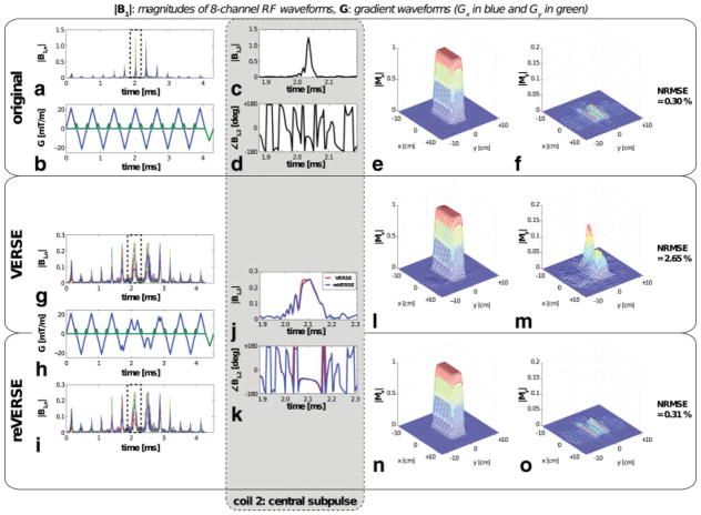
The off-resonance effects in the VERSE and reVERSE processes are summarized in Table 3 along with the results from the previous homogenous main field simulations for comparison. The off-resonance increased the NRMSEs in the VERSE pulses when compared with the homogeneous field simulations for both reshaping scenarios. Particularly, the VERSE pulse with moderate reshaping resulted in a much higher 2.65% NRMSE. As depicted in Fig. 2m, the distortion in the My magnetization is easily appreciated. The reVERSE pulses recovered the original NRMSEs in all circumstances, and the resultant peak RF magnitudes were very close to the target value, only about 0.2% higher. As parallel transmit plays RF independently, it can compensate for local ΔB0 more efficiently and can shorten pulse duration by utilizing sensitivity patterns. As observed with overlaid central subpulses of coil 2, which has the highest sensitivity for the highly off-resonant upper left corner of the target, little adjustment in reVERSE pulse successfully recovered the off-resonance-induced distortion in VERSE profile.
Table 3.
The reVERSE Approach was Validated with 2-D Spatial Excitations With Off-Resonance Correction, Designed With the Information Given in Fig. 1
| Off-resonance map, Δf0(r) (Hz) | Peak |B1,n| target | Peak |B1,n|
|
Profile NRMSE (%)
|
||||
|---|---|---|---|---|---|---|---|
| Original | VERSE | reVERSE | Original | VERSE | reVERSE | ||
| 0 | ∞ | 1.39 | 1.39 | 1.38 | 0.29 | 0.46 | 0.29 |
| 0 | 0.25 | 1.39 | 0.25 | 0.26 | 0.29 | 0.94 | 0.29 |
| Fig. 1b | ∞ | 1.25 | 1.23 | 1.24 | 0.30 | 0.43 | 0.30 |
| Fig. 1b | 0.25 | 1.25 | 0.25 | 0.26 | 0.30 | 2.65 | 0.31 |
The results of the homogeneous main field designs in Table 2 reappeared for comparison.
FIG. 2.
2-D spatial parallel excitation profiles are compared for original, VERSE, and reVERSE pulses. The RF pulse was initially designed with the information given in Fig. 1 and the VERSE reshaping aimed to reduce the peak |B1,n| from 1.25 to 0.25. The VERSE pulse distorted the profile (better appreciated in the My magnetization), which was successfully corrected by the reVERSE pulse after four iterations. Zoomed-in versions of central subpulses (indicated by the dotted boxes in Fig. a, g, and i) are compared for coil 2 in the gray box. [Color figure can be viewed in the online issue, which is available at wileyonlinelibrary.com.]
Simulation III: Dual-Band Excitation
The dual-band excitations with three different initial designs are compared in Table 4. Due to the large deviation in the peak |B1,n| with the initial reVERSE, iterative approach was used for RF pulse designs. All three reVERSE pulses ended up with lower NRMSEs than the VERSE pulses, close to the levels of their original pulses. Starting with a good initial design is very important as the quality of the initial excitation is likely to propagate throughout the iterations due to the local optimality of the reVERSE framework.
Table 4.
The Iterative reVERSE Approach was Demonstrated With Dual-Band Excitations by Comparing Three Different Initial Designs
| Gmax (mT/m) Initial design | L | Pulse duration (ms)
|
Peak |B1,n|
|
Profile NRMSE (%)
|
|||||||
|---|---|---|---|---|---|---|---|---|---|---|---|
| REV0 | REVL | REV0 | VER | REV1 | REVL | REV0 | VER | REV1 | REVL | ||
| 5.0 | 4 | 9.18 | 4.89 | 1.78 | 0.90 | 1.18 | 0.97 | 0.45 | 7.21 | 0.45 | 0.44 |
| 10.0 | 2 | 5.49 | 5.28 | 3.70 | 0.90 | 1.30 | 0.99 | 0.64 | 3.58 | 0.69 | 0.69 |
| ∞ | 3 | 4.31 | 5.46 | 6.89 | 0.90 | 2.08 | 0.98 | 1.22 | 5.42 | 1.55 | 1.21 |
Gmax, maximum gradient amplitude constraint of the initial design; L, number of iterations of the final reVERSE pulse; REVl, lth reVERSE pulse (REV0 is the original pulse); VER, VERSE pulse. Each initial pulse was designed with a specified maximum gradient amplitude constraint as shown in the leftmost column. The target peak |B1,n| of VERSE reshaping was set to 0.9, lower than the the nominal target magnitude of 1.0, for a faster convergence. Note that the same Gmax = 40 mT/m constraint was used for VERSE and reVERSE operations.
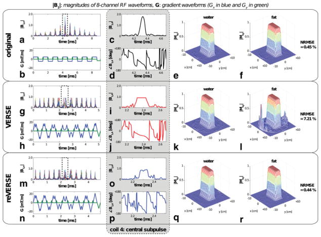
The initial design with the gradient amplitude constraint of 5 mT/m resulted in the lowest NRMSE even with the shortest pulse duration as the dilated central subpulse provides a better solution space for numerical RF design. As VERSE preserves the original excitation quality and reVERSE seeks a locally optimal solution, the final excitation accuracy achieved by the reVERSE pulse is likely to closely match that of the initial pulse. Interestingly, this also showed the worst NRMSE for the VERSE pulse due to large amount of pulse reshaping. As clearly observed in Fig. 3k, l, VERSE reshaping distorted the fat profile while preserving the water profile. Similar to EP imaging, distortion on profile shape (by the off-resonance dependent shift in space) and aliased excitation pattern (due to the inconsistent phase errors between even and odd echoes) was present along the blip direction in Fig. 3l. However, the reVERSE pulse effectively corrected both the distortions in the fat profile and the peak |B1,n| deviation after four iterations. Note that the time-efficiency of the initial design is not as important as with normal pulse designs because the following VERSE operation automatically compresses “low RF power” regions, which prevents unnecessary increase in pulse duration, especially for iterative reVERSE.
FIG. 3.
A dual-band excitation pulse, targeting both water and fat under a homogeneous main field, was initially designed with the maximum gradient amplitude constraint of 5 mT/m, and the VERSE reshaping aimed to reduce the peak |B1,n| from 1.78 to 1. The VERSE pulse preserved the water profile but significantly distorted the fat profile, which was successfully corrected by the reVERSE pulse. Zoomed-in versions of central subpulses (indicated by the dotted boxes in Fig. a, g, and m) are compared for coil 4 in the gray box. [Color figure can be viewed in the online issue, which is available at wileyonlinelibrary.com.]
The initial design without the gradient amplitude constraint resulted in a maximum gradient amplitude of 21.4 mT/m. Note that the peak RF magnitude of the reVERSE pulse was more than two times higher than the target value as shown in Fig. 4. This is quite different from the water only excitation where reVERSE pulse resulted in a very little overshoot even with the off-resonance correction. The deviation in peak RF magnitude and the amount of reshaping became smaller and smaller through iterations and the desired B1,max was achieved after only three iterations. Again, the resultant excitation profiles were comparable with the original targets.
FIG. 4.
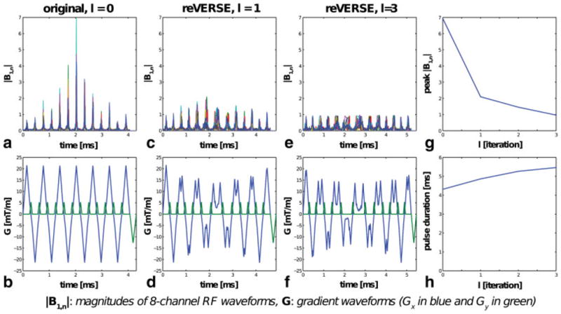
a,b: A dual-band excitation pulse was initially designed without the gradient amplitude constraint, resulting in a maximum gradient amplitude of 21.4 mT/m. c,d: The peak RF magnitude was two times higher with the pulse redesign. e,f: After three iterations, peak |B1,n| converged to the target magnitude, B1,max = 1. g,h: The peak |B1,n| deviation and the reshaping amount became smaller and smaller through iterations. [Color figure can be viewed in the online issue, which is available at wileyonlinelibrary.com.]
Experiment I: Accuracy of VERSE
With body-coil transmit, a fairly uniform pattern was observed as shown in Fig. 5a. After adjusting gradient shim parameters to reduce the off-resonance distribution across the phantom (Fig. 5b) (29), we measured the excitation profiles of the original, VERSE, reVERSE pulses. The targeted 90% peak-RF-amplitude reduction was achieved with a 15% increase in pulse duration. The experimental results (Fig. 5d) agreed well with the Bloch simulations (Fig. 5c) and both VERSE and reVERSE profiles were comparable with the original, which validates the performance of our VERSE implementation. Note that the experimental results contain erroneous stopband excitation that is not present in the simulations. This is mainly from the imperfect RF timing relative to the gradients and was worse for the original pulse. But, the error level was reduced with VERSE and reVERSE pulses as they were played with lower gradient amplitudes.
FIG. 5.
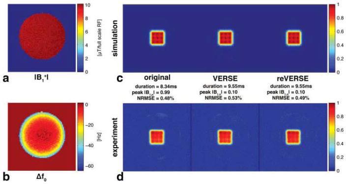
Simulation and experimental results for body-coil transmit. The original pulse was designed with the measured field maps on the left column, and the VERSE operation was performed targeting peak |B1,n| = 0.1, 10% of the original peak value. a: Transmit-sensitivity pattern of body-coil transmit, b: off-resonance map, c: Bloch-simulated profiles, and d: experimental profiles. [Color figure can be viewed in the online issue, which is available at wileyonlinelibrary.com.]
Experiment II: Off-Resonance Correction
As intended, significant field inhomogeneity was created, as in Fig. 6b, with a maximum field offset of 500 Hz across the phantom along with the signal voids near the attached metal piece (Fig. 6a, b). With the VERSE pulse, the profile shape was distorted due to the off-resonance and an aliased excitation pattern was also present in both simulated and experimental profiles, similar to Fig. 3l. The reVERSE pulse restored the profile shape and suppressed the aliased excitation in stopband although some residual error persisted near the signal voids as predicted with the Bloch simulation.
FIG. 6.
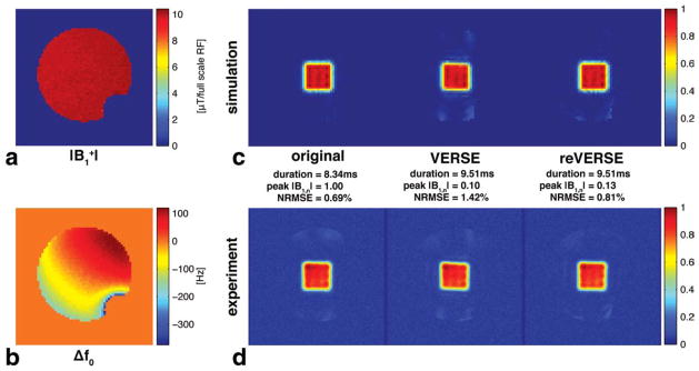
Simulation and experimental results for body-coil transmit with off-resonance distribution (about 500 Hz offset across the phantom). The original pulse was designed with the measured field maps on the left column and VERSE operation was performed targeting peak |B1,n| = 0.1, 10% of the original peak value. With the VERSE pulse, the profile was distorted by the off-resonance. Also, aliased excitation patterns were present in both simulation and experimental profiles. The reVERSE pulse restored the profile shape and suppressed the aliased excitation in stopband although some residual error persisted near the signal voids as predicted with the Bloch simulation.
Experiment III: Parallel Transmit
After acquiring the field maps in Fig. 7a, b, a pulse was initially designed with the hardware constraint of Gmax = 40 mT/m. However, this resulted in peak |B1,n| = 1.57 and NRMSE = 1.16%. Thus, we lowered Gmax to 10 mT/m to achieve a 10° flip angle within the RF hardware limit. Note that the NRMSE of the initial pulse was also improved from 1.16% to 0.66% by doing so. In the simulated profiles (Fig. 7c), aliased excitation error was observed in all three profiles; this imperfect cancellation was caused mostly by the sensitivity patterns in Fig. 7a and similar experimental results were observed even when the off-resonance distribution was minimal. Also, the VERSE profile showed off-resonance-induced distortion, and aliased excitation error was further increased. Theses observations agreed well with the experimental results in Fig. 7d. Although the reVERSE pulse was 25% shorter than the original pulse, it maintained the profile fidelity with the reduced peak |B1,n|.
FIG. 7.
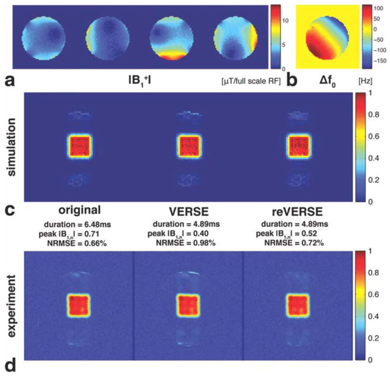
Simulation and experimental results for parallel transmit. a: Transmit-sensitivity patterns of a four-channel system, b: off-resonance map, c: Bloch-simulated profiles, and d: experimental profiles. About 300 Hz off-resonance offset was created by changing gradient-shim values. Bmax = 0.5 (i.e., 50% of the full scale RF) was targeted through reVERSE method (with α = 0.8). Although the reVERSE pulse was 25% shorter than the original pulse, it maintained the profile fidelity with the reduced peak |B1,n|.
CONCLUSION AND DISCUSSION
To improve the robustness of VERSE with numerically designed RF pulses, we have improved the fidelity of VERSE implementation by oversampling waveforms within the VERSE algorithm and designing gradient waveforms with a shorter update time. This improves the registration accuracy of the RF-to-gradient amplitude ratio within VERSE. Also, an iterative approach has been introduced to resolve the potential deviation of peak RF magnitude of reVERSE pulse from the target value. The proposed reVERSE algorithm was experimentally validated as a practical RF pulse design framework in parallel excitation, providing online controllability of peak RF power while compensating for off-resonance as well.
Sharing the same weakness as VERSE, the performance of our proposed method degrades with increased gradient nonlinearity and off-resonance because the nonuniform pulse reshaping makes pulses more sensitive to such non-idealities. Although the uniformly dilated pulses are also sensitive to them, their effects are generally more benign. For EP trajectories, off-resonance primarily manifests as profile shifting rather than blurring and gradient nonlinearity is easier to correct.
As demonstrated with our experiments, slowly varying off-resonance in space can be compensated with the reVERSE approach. However, nonuniform reshaping by VERSE may degrade the performance over an off-resonance bandwidth because the resultant nonconstant gradient makes the off-resonance-induced phase accrual nonlinear in k space. Thus, the performance over bandwidth needs to be taken into account when a wide range of frequencies needs to be excited or when field-map-based approach is ineffective due to the presence of nonsmooth off-resonances by local susceptibility and at fat-water interfaces. A lengthy pulse, especially when numerically designed at a single frequency, is more vulnerable to such effects, and the sensitivity is higher for high-field applications as field inhomogeneity scales with B0. When the bandwidth performance is unacceptable, the degree of attenuation may need to be limited within VERSE or a broadband RF excitation approach (23) should be used within the RF designs to mitigate the problem.
In our experiments, we did not correct gradient nonlinearities other than the relative timing of RF to gradient with 2-μs precision. Though our experimental results agreed fairly well with simulations, the performance of VERSE’d pulses would degrade with increased roughness in the VERSE’d gradient waveforms which can be caused by aggressive RF attenuation, high acceleration factors in parallel transmit, and large flip angles. For situations with considerable nonlinearities, the performance of both VERSE and reVERSE should be improved by adopting the approach suggested by Hargreaves et al. in Ref. 14: smoothing gradient waveforms and using a measured k-space trajectory (30) for both VERSE and reVERSE. Enforcing smoothness in the VERSE’d gradient waveforms mitigates the unpredictable gradient amplifier response to the sharp edges, and gradient measurements allow us to correct other nonidealities such as gradient hardware imperfections, eddy-current effects, and RF group delay.
A gradient-smoothing operation can be effectively done with the gradient upper bound concept, introduced in the time-optimal VERSE design (19). Smooth gradient waveforms can be achieved simply by replacing the original gradient upper bound Gu(s) with a smooth gradient upper bound within the time-optimal VERSE algorithm. Consequently, this approach guarantees the same k-space trajectory and the calculation of the VERSE pulse with is as straightforward as the original time-optimal VERSE design. Generally, so long as is satisfied, a gradient upper bound can be set to any that mitigates gradient nonidealities. For example, we can impose smoothness, convexity, and symmetry on the shape of gradient waveforms in addition to the gradient amplitude and slew rate limits, which is very difficult, if not impossible, to achieve online with other time-domain approaches.
In multidimensional VERSE, gradient nonidealities can distort k-space trajectories and, thus, the gradient iterative predistortion approach (31) would be more suitable as the gradient nonideality is directly compensated by pre-distorting the gradient waveforms such that the nominal waveforms are actually played on gradient hardware. This approach would be particularly useful if online RF pulse redesign is unnecessary or infeasible, or the computational cost of online RF pulse design is too high to be practical.
For the iterative reVERSE approach, we assumed that the peak RF magnitude decreases through each iteration. Generally, this is a reasonable assumption considering that the VERSE’d RF is close to the solution of the subsequent pulse design problem. However, it is possible that the reVERSE pulse would end up with a higher peak RF magnitude than the previous iteration, such as when the RF design aggressively optimizes other parameters (e.g., profile fidelity) than the RF power or when the previous deviation in peak RF itself is very small. Thus, to improve the convergence behavior of the algorithm, peak RF power should be properly penalized in the RF design while the B1,max being attenuated in the VERSE. Alternatively, peak RF magnitudes can be guided by predetermined (or adaptive) thresholds through iterations to enforce the decrease and convergence. This can be easily implemented without increasing the complexity of RF design methods as it is not a hard constraint on the peak RF but a stopping criterion of the optimization.
Acknowledgments
Grant sponsor: NIH; Grant numbers: 41RR09784, R21EB007715, R01EB005307; Grant sponsor: GE Healthcare
References
- 1.Pauly J, Nishimura D, Macovski A. A k-space analysis of small-tip-angle excitation. J Magn Reson Imaging. 1989;81:43–56. doi: 10.1016/j.jmr.2011.09.023. [DOI] [PubMed] [Google Scholar]
- 2.Katscher U, Börnert P, Leussler C, van den Brink JS. Transmit SENSE. Magn Reson Med. 2003;49:144–150. doi: 10.1002/mrm.10353. [DOI] [PubMed] [Google Scholar]
- 3.Zhu Y. Parallel excitation with an array of transmit coils. Magn Reson Med. 2004;51:775–784. doi: 10.1002/mrm.20011. [DOI] [PubMed] [Google Scholar]
- 4.Grissom W, Yip CY, Zhang Z, Stenger VA, Fessler JA, Noll DC. Spatial domain method for the design of RF pulses in multicoil parallel excitation. Magn Reson Med. 2006;56:620–629. doi: 10.1002/mrm.20978. [DOI] [PubMed] [Google Scholar]
- 5.Yip CY, Grissom WA, Fessler JA, Noll DC. Joint design of trajectory and RF pulses for parallel excitation. Magn Reson Med. 2007;58:598–604. doi: 10.1002/mrm.21262. [DOI] [PubMed] [Google Scholar]
- 6.Xu D, King KF, Zhu Y, McKinnon GC, Liang ZP. Designing multichannel, multidimensional, arbitrary flip angle RF pulses using an optimal control approach. Magn Reson Med. 2008;59:547–560. doi: 10.1002/mrm.21485. [DOI] [PMC free article] [PubMed] [Google Scholar]
- 7.Grissom WA, Yip CY, Wright SM, Fessler JA, Noll DC. Additive angle method for fast large-tip-angle RF pulse design in parallel excitation. Magn Reson Med. 2008;59:779–787. doi: 10.1002/mrm.21510. [DOI] [PubMed] [Google Scholar]
- 8.Setsompop K, Wald LL, Alagappan V, Gagoski BA, Adalsteinsson E. Magnitude least squares optimization for parallel radio frequency excitation design demonstrated at 7 Tesla with eight channels. Magn Reson Med. 2008;59:908–915. doi: 10.1002/mrm.21513. [DOI] [PMC free article] [PubMed] [Google Scholar]
- 9.Katscher U, Röhrs J, Börnert P. Basic considerations on the impact of the coil array on the performance of transmit SENSE. MAGMA. 2005;18:81–88. doi: 10.1007/s10334-004-0096-y. [DOI] [PubMed] [Google Scholar]
- 10.Cunningham CH, Wright GA, Wood ML. High-order multiband encoding in the heart. Magn Reson Med. 2002;48:689–698. doi: 10.1002/mrm.10277. [DOI] [PubMed] [Google Scholar]
- 11.Yip CY, Fessler JA, Noll DC. Iterative RF pulse design for multidimensional, small-tip-angle selective excitation. Magn Reson Med. 2005;54:908–917. doi: 10.1002/mrm.20631. [DOI] [PubMed] [Google Scholar]
- 12.Conolly S, Nishimura D, Macovski A, Glover G. Variable-rate selective excitation. J Magn Reson. 1988;78:440–458. [Google Scholar]
- 13.Conolly S, Glover G, Nishimura D, Macovski A. A reduced power selective adiabatic spin-echo pulse sequence. Magn Reson Med. 1991;18:28–38. doi: 10.1002/mrm.1910180105. [DOI] [PubMed] [Google Scholar]
- 14.Hargreaves BA, Cunningham CH, Nishimura DG, Conolly SM. Variable-rate selective excitation for rapid MRI sequences. Magn Reson Med. 2004;52:590–597. doi: 10.1002/mrm.20168. [DOI] [PubMed] [Google Scholar]
- 15.Gai ND, Zur Y. Design and optimization for variable rate selective excitation using an analytic RF scaling function. J Magn Reson. 2007;189:78–89. doi: 10.1016/j.jmr.2007.08.017. [DOI] [PubMed] [Google Scholar]
- 16.Xu D, King KF, Liang ZP. Variable slew-rate spiral design: theory and application to peak B1 amplitude reduction in 2D RF pulse design. Magn Reson Med. 2007;58:835–842. doi: 10.1002/mrm.21375. [DOI] [PubMed] [Google Scholar]
- 17.Wu X, Akgun C, Vaughan JT, Ugurbil K, Van de Moortele PF. SAR reduction in transmit SENSE using adapted excitation k-space trajectories. Proceedings of the 15th Annual Meeting of ISMRM; Berlin, Germany. 2007. p. 673. [Google Scholar]
- 18.van den Bos IC, Hussain SM, Krestin GP, Wielopolski PA. Extending slice coverage for breathhold fat-suppressed T2-weighted fast spin-echo of the liver at 3. 0 T: application of variable-rate selective-excitation (VERSE) RF pulses. J Magn Reson Imaging. 2008;27:110–116. doi: 10.1002/jmri.21215. [DOI] [PubMed] [Google Scholar]
- 19.Lee D, Lustig M, Grissom WA, Pauly JM. Time-optimal design for multidimensional and parallel transmit variable-rate selective excitation. Magn Reson Med. 2009;61:1471–1479. doi: 10.1002/mrm.21950. [DOI] [PMC free article] [PubMed] [Google Scholar]
- 20.Lustig M, Kim SJ, Pauly JM. A fast method for designing time-optimal gradient waveforms for arbitrary k-space trajectories. IEEE Trans Med Imaging. 2008;27:866–873. doi: 10.1109/TMI.2008.922699. [DOI] [PMC free article] [PubMed] [Google Scholar]
- 21.Grissom WA, Xu D, Kerr AB, Fessler JA, Noll DC. Fast large-tip-angle multidimensional and parallel RF pulse design in MRI. IEEE Trans Med Imaging. 2009;28:1548–1559. doi: 10.1109/TMI.2009.2020064. [DOI] [PMC free article] [PubMed] [Google Scholar]
- 22.Kerr AB, Etezadi-Amoli M, Fautz HP, Vogel MW, Gross P, Zhu Y, Pauly JM. Dual-band RF shimming at high-field with parallel excitation. Proceedings of the 16th Annual Meeting of ISMRM; Toronto, Canada. 2008. p. 617. [Google Scholar]
- 23.Setsompop K, Alagappan V, Gagoski B, Potthast A, Hebrank F, Fontius U, Schmitt F, Wald L, Adalsteinsson E. Broadband slab selection with B1 + mitigation at 7 T via parallel spectral-spatial excitation. Magn Reson Med. 2009;61:493–500. doi: 10.1002/mrm.21834. [DOI] [PMC free article] [PubMed] [Google Scholar]
- 24.Kurpad KN, Boskamp EB, Wright SM. A parallel transmit volume coil with independent control of currents on the array elements. Proceedings of the 13th Annual Meeting of ISMRM; Miami Beach. 2005. p. 16. [Google Scholar]
- 25.Wright SM. 2D full-wave modeling of SENSE coil geometry factors at high-fields. Proceedings of the 10th Annual Meeting of ISMRM; Honolulu. 2002. p. 854. [Google Scholar]
- 26.Sacolick LI, Wiesinger F, Hancu I, Vogel MW. B1 mapping by Bloch-Siegert shift. Magn Reson Med. 2010;63:1315–1322. doi: 10.1002/mrm.22357. [DOI] [PMC free article] [PubMed] [Google Scholar]
- 27.Schneider E, Glover G. Rapid in vivo proton shimming. Magn Reson Med. 1991;18:335–347. doi: 10.1002/mrm.1910180208. [DOI] [PubMed] [Google Scholar]
- 28.Stang P, Kerr A, Pauly J, Scott G. An extensible transmit array system using vector modulation and measurement. Proceedings of the 16th Annual Meeting of ISMRM; Toronto, Canada. 2008. p. 145. [Google Scholar]
- 29.Irarrazabal P, Meyer CH, Nishimura DG, Macovski A. Inhomogeneity correction using an estimated linear field map. Magn Reson Med. 1996;35:278–282. doi: 10.1002/mrm.1910350221. [DOI] [PubMed] [Google Scholar]
- 30.Duyn JH, Yang Y, Frank JA, van der Veen JW. Simple correction method for k-space trajectory deviations in MRI. J Magn Reson. 1998;132:150–153. doi: 10.1006/jmre.1998.1396. [DOI] [PubMed] [Google Scholar]
- 31.Grissom WA, Kerr AB, Stang PP, Lustig M, Scott GC, Pauly JM. GrIP: gradient iterative predistortion for multidimensional and parallel excitation. Proceedings of the 18th Annual Meeting of ISMRM; Stockholm, Sweden. 2010. p. 4925. [Google Scholar]


