Abstract
Retinal development is a dynamic process both anatomically and functionally. High-resolution imaging and dynamic monitoring of photoreceptors and inner neurons can provide important information regarding the structure and function of the developing retina. In this chapter, we describe intrinsic optical signal (IOS) imaging as a high spatiotemporal resolution method for functional study of living retinal tissues. IOS imaging is based on near infrared (NIR) light detection of stimulus-evoked transient change of inherent optical characteristics of the cells. With no requirement for exogenous biomarkers, IOS imaging is totally noninvasive for functional mapping of stimulus-evoked spatiotemporal dynamics of the photoreceptors and inner retinal neurons.
Keywords: Retinal function, Photoreceptor, Neuron, Ganglion, Electrophysiology, Optical imaging, Intrinsic optical signal
1. Introduction
As one part of the central nervous system, the retina plays a vital role in capturing photons, converting light energy to electrical signals, and several preliminary stages of visual information processing. For these, retinal photoreceptors and inner neurons form complex networks, with both feed-forward and feed-back mechanisms among different retinal layers/cells. During development, the retina displays conspicuous anatomic and functional dynamics of its photoreceptors and inner neurons (1, 2). Given the delicate structure and complex function of the retina, advanced understanding of retinal development and retinal neural information processing require the capability to simultaneously monitor dynamic activities of large populations of retinal neurons, with high-spatial and high-temporal resolution.
Electrophysiological methods, such as electroretinogram (ERG), have provided valuable information for functional study of the retina (3, 4), but high-resolution monitoring of multiple types of retinal cells functioning together is still challenging. In principle, optical methods can provide high-resolution imaging of the retina and other biological tissues. A variety of voltage-sensitive dyes and ion-selective indicators have been developed to allow functional imaging of neural activities. However, phototoxicity of the dyes and difficult loading procedures limit their application for functional study of the retina.
Stimulus-evoked intrinsic optical signals (IOSs) have been detected in the retina (5–7), and other neural tissues (8, 9). Fast IOSs have time courses that are comparable to stimulus-evoked electrophysiological kinetics and thus hold promise for high spatiotemporal resolution investigation of retinal neural function. Without the requirement of exogenous biomarkers, IOS imaging is totally noninvasive for dynamic monitoring of retinal neural activities. We have recently validated high-spatial (~μm) and high-temporal (ms) resolution IOS imaging of retinal neural activities in isolated, but living, retinal tissues (10–15). In principle, both flat-mounted (14) and sliced (12) retinas can be used for functional study of the retina. Flat-mounted retinas provide a simple preparation for depth-resolved mapping of neural activities at individual functional layers; while sliced retinas allow parallel monitoring of visual signal propagation from the photoreceptors to inner retinal neurons. In this article, flat-mounted Leopard frog (Rana pipiens) retina is taken as an example to illustrate the retinal preparation and IOS imaging procedures. The rationale of basic IOS imaging and dynamic differential IOS processing is reviewed.
2. Materials
Construct an IOS imager. Keep imaging optics clean and dry. Acquire animals from certified vendors. Prepare Ringer’s solution under room temperature with purified deionized water and analytical grade reagents. Carefully follow waste disposal regulations when disposing chemical waste.
2.1. Imaging Equipment
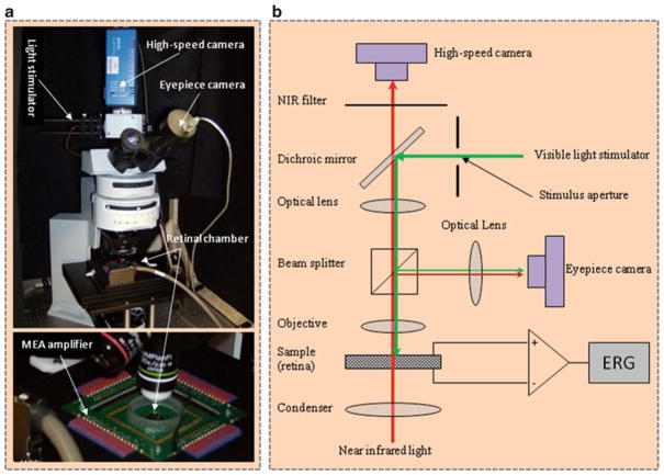
A conventional microscope can be modified to conduct IOS imaging of living retinal tissues. Major components of the system shown in Fig. 1 are summarized as follows:
Fig. 1.
Photograph (left) and optical diagram (right) of the near infrared (NIR) light microscope for intrinsic optical signal (IOS) imaging. During measurements, isolated frog retina is illuminated continuously by the NIR light. The visible light stimulator is used to produce a visible light flash for retinal stimulation. A MEA system is used for concurrent electroretinogram (ERG) measurement of retinal activation. The dichroic mirror reflects visible stimulus light and passes the NIR recording light. The eyepiece camera is used to adjust visible light stimulus aperture at the retina. In order to ensure light efficiency for intrinsic optical signal imaging, the beam splitter is removed from the optical path after the visible light stimulator is adjusted. The NIR filter before the high-speed camera is used to block visible stimulus light, and allow the NIR probe light to reach the detector for recording stimulus-evoked IOSs. (This figure is modified from Yao (13)).
Optical platform: a light microscope with water dipping objective (see Note 1).
Light sources: the imaging system consists of two, i.e., visible and NIR, light sources. The visible light is used for retinal stimulation, and the NIR light is used for IOS recording of retinal response (see Note 2).
High-speed camera: for NIR recording of stimulus-evoked IOSs in the retina (see Note 3).
Eyepiece camera: for test and adjustment of stimulus light patterns.
NIR filter: to block visible light and pass NIR light into the high-speed camera.
Dichroic mirror: to reflect visible stimulus light and pass the NIR recording light.
Beam splitter: to split the light into the high-speed camera and eyepiece camera (see Note 4).
Retinal chamber: to hold the sample for concurrent IOS imaging and ERG measurement (see Note 5).
ERG system: for electrophysiological measurement of the retina (see Note 6).
Timing controller: for electronic synchronization of retinal stimulation and data acquisition (see Note 7).
2.2. Animal
Animal species: Leopard frogs (Rana Pipiens) (Kons Scientific, Germantown, WI, USA) were used to collect representative IOS images shown in this article. Other animal species is applicable.
Ringer’s solution: refer to literatures to select appropriate Ringer’s solution for specific animal species. For Leopard frogs (Rana pipiens) used in our experiments, the Ringer’s solution contains (16): 110 mM NaCl, 2.5 mM KCl, 1.6 mM MgCl2, 1.0 mM CaCl2, 22 mM NaHCO3, and 10 mM d-glucose (see Note 8).
2.3. Surgical Equipment
Animal guillotine for animal decapitation (World Precision Instrument Inc., Sarasota, FL, USA).
Dissecting microscope with dim red light illumination (Fisher Scientific Inc., Pittsburgh, PA, USA).
Surgical forceps with 0.1 × 0.06-mm tip (World Precision Instrument).
McPherson-Vannas scissors with 0.1-mm straight tip (World Precision Instrument).
Pithing needle.
3. Methods
3.1. Retinal Preparation
All animal procedures are approved by the Institutional Animal Care and Use Committee (IACUC).
Dark adaptation: conduct dark adaptation as needed (see Note 9).
Animal euthanasia: after dark adaptation, the frog is euthanized by rapid decapitation and followed by double pithing.
Transfer the frog head into a Petri dish filled with frog’s Ringer solution (see Note 10).
Eye isolation: enucleate both eyeballs from the frog head with a pair of dissecting scissors, transfer one eye into a new Petri dish filled with fresh Ringer’s solution for retinal dissection, and store the other one in Ringer solution for backup experiment.
Retinal dissection: the procedure is performed in Ringer’s solution. Trim off excess tissues around the eye ball with a pair of Vannas scissors. Hemisect the eyeball below the equator with fine scissors to remove the lens and anterior structures. Carefully separate the retina from retinal pigment epithelium (RPE) with a pair of surgical forceps.
Retinal transfer: delicately transfer the isolated retina into the recording chamber, with the photoreceptor side facing towards the objective.
Retinal fixation: flatten out the retina in the chamber (see Note 11), cover the retina with a micromesh sheet (see Note 12), and fill the chamber with fresh Ringer’s solution (see Note 13).
3.2. Retinal Imaging
Warm up the IOS imager (Fig. 1).
Test and adjust the imaging parameters, including image size, resolution, and frame rate, of the high-speed camera.
Test and adjust the retinal stimulator, including stimulus aperture/pattern, color, and intensity.
Test and adjust IOS parameters, including pre-stimulus recording phase, stimulus duration, and post-stimulus recording phase.
Place the retinal preparation under the IOS imager.
Identify a retinal area for IOS imaging.
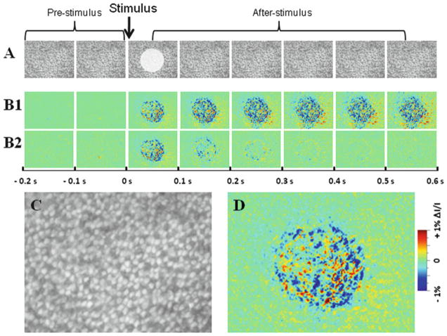
Focus the NIR light to the interested retinal depth, such as photoreceptor layer (Fig. 2).
Record a retinal image sequence, with retinal stimulation, into the built-in RAM of the high-speed camera (PCO1200, PCO AG, Kelheim, Germany).
Transfer and save the image video to computer disk.
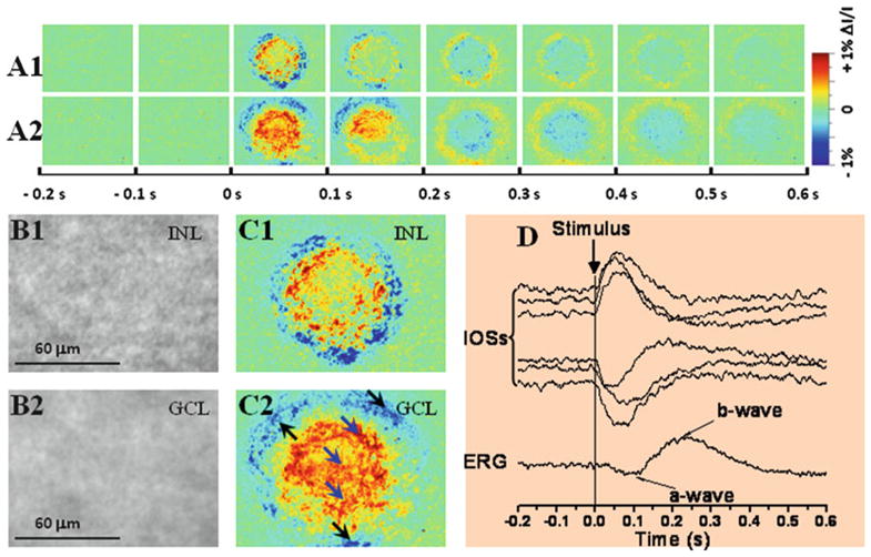
Change the focus plane to other interested retinal depth, such as ganglion cell layer (Fig. 3).
Repeat steps 8 and 9.
Repeat steps 6–11 for imaging other retinal areas.
Fig. 2.
Intrinsic optical signal (IOS) imaging of retinal photoreceptors. The raw images (a) were recorded with the CMOS camera at a speed of 1,000 frames/s. The white spot in the third frame of the image sequence (a) shows the visible stimulus pattern. (b1, b2) Reconstructed IOS and dynamic differential IOS images, respectively, based on the raw images in (a). Each illustrated frame is an average over 100 ms interval (100 frames); 200 ms pre-stimulus and 600 ms post-stimulus images are shown. (c, d) Enlarged images of the third frames shown in (a) and (c), respectively.
Fig. 3.

Intrinsic optical signal (IOS) imaging of inner retinal neurons. (a1, a2) Dynamic differential IOS images of inner nuclear layer (INL) and ganglion cell layer (GCL). (b1, b2) Representative raw images of the INL and GCL. (c1, c2) Enlarged images of the third frames shown in (a1) and (a2), respectively. (d) IOS response of individual pixels pointed by arrowheads in (c2). Simultaneous electroretinogram (ERG) was recorded to show stimulus-evoked electrophysiological response of the retina. Vertical line indicates the stimulus onset and offset. The raw images were recorded with the CMOS camera at a speed of 1,000 frames/s. (This figure is modified from Yao (14)).
3.3. Image Processing and IOS Analysis
Select one programming language, such as MATLAB or Interactive Data Language (IDL), for data processing. As shown in Figs. 2 and 3, the unit of IOS images is ΔI/I, where ΔI is the stimulus-evoked dynamic optical changes and I is the background light intensity.
Basic IOS images can be constructed using the following procedure (14):
The raw images (Fig. 2a) from the pre-stimulus baseline recording phase is averaged, pixel by pixel, and the averaged intensity of each pixel is taken as the background intensity I of each pixel.
The background intensity I is subtracted from each subsequent recorded frame, pixel by pixel, to get the ΔI of each pixel.
The ΔI/I image sequence is constructed to show the dynamic optical changes correlated with retinal activation (Fig. 2b).
Dynamic differential IOS images (Fig. 2c) can be constructed (10, 17):
| (1) |
where It(x,y) is the intensity value of a pixel (x, y) at a time point t; Iref (x,y) is the dynamic reference baseline of m consecutive frames, which can be quantified by:
| (2) |
In other words, the averaged pixel value of m consecutive frames recorded before the time point t is used as a reference baseline to calculate the differential IOS. For the dynamic differential IOSs shown in this article, we selected m=100 (i.e., images recorded over 100 ms) for the dynamic reference baseline.
Based on the IOS image sequence, stimulus-evoked retinal dynamics can be analyzed with single pixel spatial-resolution (Fig. 3b) and ms temporal-resolution (Fig. 3c). Further IOS image processing and analysis can be conducted as needed.
Acknowledgments
This work was supported in part by Dana Foundation (Brain and Immuno-Imaging Grant program), Eyesight Foundation of Alabama, National Institutes of Health (R21RR025788 and R21EB012264), and National Science Foundation (CBET-1055889).
Footnotes
Both upright and inverted microscopes are applicable. For the representative IOS imager shown in Fig. 1, an upright microscope (BX51WI, Olympus America Inc., Center Valley, PA, USA) is used. In the imager, a water dipping objective is used to reduce the effect of water fluctuations.
In Fig. 1, the NIR light is produced by a 12-V 100-W halogen lamp (PHILIPS7724) with a band-pass filter (wavelength band: 800–1,000 nm) in front, and the visible light stimulator is a fiber-coupled white light emitting diode (LED). The overall power of the NIR light delivered at the retina is ~1 mW.
The images shown in this chapter were recorded using a 10-bit CMOS camera (PCO1200, PCO AG), running at a frame rate of 1,000 Hz and frame resolution of 400 × 400 pixels. The CMOS camera has 2 GB built-in RAM for fast image recording with a transfer speed of 820 MB/s. The ultrafast transfer speed made it possible to collect optical images at a high frame rate while allowing sufficient exposure time to ensure image quality.
In order to ensure light efficiency for IOS imaging, the beam splitter should be removed from the optical path after adjusting the visible light stimulator.
For transmission IOS imaging, the chamber should be transparent for NIR light. A multiple electrode array (MEA) plate with glass ring (100/10-ITO-gr, ALA Scientific Instrumentations) was used for recording the IOS images shown in Figs. 2 and 3.
Combined electrophysiological recording is helpful for the assessment of retinal viability. For the IOS imager shown in Fig. 1, a 60-channel electrophysiology recording system (MEA1060, ALA Scientific Instrumentations) is integrated.
Either commercial functional generator or customer-designed electronic system can be used for timing control of the retinal stimulation and date acquisition. For the system shown in Fig. 1, a commercial four-channel digital delay/pulse generator (DG535, Stanford Research Systems Inc., Sunnyvale, CA, USA) is used to synchronize the retinal stimulation and data recording.
Sodium bicarbonate (NaHCO3) is required to adjust the pH to 7.3–7.45. Add NaHCO3 after the calcium chloride (CaCl2) is completely dissolved in order to prevent precipitation.
For our frog experiments, 1–2 h dark adaptation is typically conducted. Increased time period for dark adaptation makes it easier for separating the retina from the RPE.
Ice-cold solution can be helpful to slow down retinal metabolic activities during the surgery, thus to increase retinal viability for IOS imaging.
Slice the isolated retina radically, and thus allow it to lie flat in the recording chamber.
Press micromesh sheet gently to avoid retinal damage.
A perfusion system is useful to keep the viability of isolated retinas.
References
- 1.Sernagor E, Eglen SJ, Wong RO. Development of retinal ganglion cell structure and function. Prog Retin Eye Res. 2001;20:139–174. doi: 10.1016/s1350-9462(00)00024-0. [DOI] [PubMed] [Google Scholar]
- 2.Berardi N, Pizzorusso T, Maffei L. Critical periods during sensory development. Curr Opin Neurobiol. 2000;10:138–145. doi: 10.1016/s0959-4388(99)00047-1. [DOI] [PubMed] [Google Scholar]
- 3.Saszik S, Bilotta J, Givin CM. ERG assessment of zebrafish retinal development. Vis Neurosci. 1999;16:881–888. doi: 10.1017/s0952523899165076. [DOI] [PubMed] [Google Scholar]
- 4.Speer CM, Sun C, Chapman B. Activity-dependent disruption of intersublaminar spaces and ABAKAN expression does not impact functional on and off organization in the ferret retinogeniculate system. Neural Dev. 2011;6:7. doi: 10.1186/1749-8104-6-7. [DOI] [PMC free article] [PubMed] [Google Scholar]
- 5.Harary HH, Brown JE, Pinto LH. Rapid light-induced changes in near infrared transmission of rods in Bufo marinus. Science (New York, NY) 1978;202:1083–1085. doi: 10.1126/science.102035. [DOI] [PubMed] [Google Scholar]
- 6.Pepperberg DR, Kahlert M, Krause A, Hofmann KP. Photic modulation of a highly sensitive, near infrared light-scattering signal recorded from intact retinal photoreceptors. Proc Natl Acad Sci USA. 1988;85:5531–5535. doi: 10.1073/pnas.85.15.5531. [DOI] [PMC free article] [PubMed] [Google Scholar]
- 7.Dawis SM, Rossetto M. Light-evoked changes in near-infrared transmission by the ON and OFF channels of the anuran retina. Vis Neurosci. 1993;10:687–692. doi: 10.1017/s0952523800005381. [DOI] [PubMed] [Google Scholar]
- 8.Cohen LB, Keynes RD, Hille B. Light scattering and birefringence changes during nerve activity. Nature. 1968;218:438–441. doi: 10.1038/218438a0. [DOI] [PubMed] [Google Scholar]
- 9.Tasaki I, Watanabe A, Sandlin R, Carnay L. Changes in fluorescence, turbidity, and birefringence associated with nerve excitation. Proc Natl Acad Sci USA. 1968;61:883–888. doi: 10.1073/pnas.61.3.883. [DOI] [PMC free article] [PubMed] [Google Scholar]
- 10.Li YG, Zhang QX, Liu L, Amthor FR, Yao XC. High spatiotemporal resolution imaging of fast intrinsic optical signals activated by retinal flicker stimulation. Opt Express. 2010;18:7210–7218. doi: 10.1364/OE.18.007210. [DOI] [PMC free article] [PubMed] [Google Scholar]
- 11.Li YG, Liu L, Amthor F, Yao XC. High-speed line-scan confocal imaging of stimulus-evoked intrinsic optical signals in the retina. Opt Lett. 2010;35:426–428. doi: 10.1364/OL.35.000426. [DOI] [PMC free article] [PubMed] [Google Scholar]
- 12.Li YC, Strang C, Amthor F, Liu L, Li YG, Zhang QX, Keyser K, Yao XC. Parallel optical monitoring of visual signal propagation from the photoreceptors to inner retina layers. Opt Lett. 2010;35:1810–1812. doi: 10.1364/OL.35.001810. [DOI] [PMC free article] [PubMed] [Google Scholar]
- 13.Yao XC. Intrinsic optical signal imaging of retinal activation. Jpn J Ophthalmol. 2009;53:327–333. doi: 10.1007/s10384-009-0685-4. [DOI] [PubMed] [Google Scholar]
- 14.Yao XC, Zhao YB. Optical dissection of stimulus-evoked retinal activation. Opt Express. 2008;16:12446–12459. doi: 10.1364/oe.16.012446. [DOI] [PubMed] [Google Scholar]
- 15.Zhang QX, Wang JY, Liu L, Yao XC. Microlens array recording of localized retinal responses. Opt Lett. 2010;35:3838–3840. doi: 10.1364/OL.35.003838. [DOI] [PMC free article] [PubMed] [Google Scholar]
- 16.Sieving PA, Murayama K, Naarendorp F. Push-pull model of the primate photopic electroretinogram: a role for hyperpolarizing neurons in shaping the b-wave. Vis Neurosci. 1994;11:519–532. doi: 10.1017/s0952523800002431. [DOI] [PubMed] [Google Scholar]
- 17.Yao XC, Liu L, Li YG. Intrinsic optical signal imaging of retinal activity in frog eye. J Innov Opt Health Sci. 2009;2:201–208. [Google Scholar]


